
Related Manuals for rotork CML-250


Summary of Contents for rotork CML-250
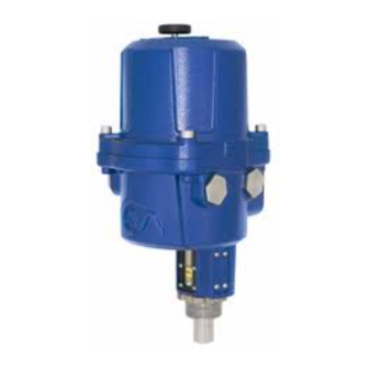
- Page 1 Range Installation & Maintenance Instructions Linear, Rotary and Quarter-Turn Control Valve Actuators Redefining Flow Control...
-
Page 2: Table Of Contents
Contents section page Introduction General Information Hazardous Area Approvals Installation & Setup Mounting the Actuator Electrical Installation Basic Setup Menu Structure Status (Alarms), Fault History & Default Menus Fault History Menu Default Menu Advanced Menu Dimensional Drawings Power Ratings Quarter-Turn Linear CML Rotary CMR ThIs MAnuAL ConTAIns IMpoRTAnT sAfeTy... -
Page 3: Introduction
The following instructions must be followed and integrated with your safety program when installing and using Rotork Process Controls products: • Read and save all instructions prior to installing, operating and servicing this product. -
Page 4: General Information
This manual has been produced to enable a competent user Only Rotork approved actuator replacement parts should to install, operate, adjust and inspect the Rotork Range of be used. Under no circumstances should any modification or alteration be carried out on the actuator, as this could Compact Control Valve Actuators. - Page 5 With a minimum resolution of 0.2% of full stroke for Linear See page 7 for full details. & Quarter-turn units and 0.6% of full stroke for Multi-turn, the Rotork CMA range helps to maximize product quality CMQ - Quarter-Turn Actuators and plant capacity.
- Page 6 general Information Advanced engineering Linear Actuator Quarter-Turn Actuator Rotary Actuator 1 encoder Technology 3 dC brushless Motor The CMA utilizes absolute encoder technology where a The CMA uses a high efficiency, continuous rated, brushless unique digital code corresponds to the angular position DC motor.
- Page 7 Model (lbf) (lbf) (inches/sec) (mm/sec) (inches) (mm) CML-100 177.9 444.8 0.25 6.35 38.1 CML-250 444.8 1112 0.125 3.18 38.1 CML-750 1334.5 3336.2 0.063 1.68 50.8 CMQ: Quarter-Turn Actuator Min Torque Min Torque Max Torque Max Torque...
- Page 8 IdenTIfICATIon LAbeL eQuIpMenT ReTuRn An identification label is attached to each actuator. When If your Rotork actuator has been correctly installed and sealed ordering parts, requesting information or service assistance, it will give years of trouble free service. please provide all of the label information. you must supply the serial number with all enquiries.
-
Page 9: Hazardous Area Approvals
hazardous Area Approvals The CMA is suitable for both indoor and outdoor use up to an altitude of 5,000 m and is watertight to IP67. Refer to the actuator nameplate for it’s specific approval details. european - hazardous Area ATeX (94/9/eC) II 2 c T4 gd usA - hazardous Area ex d IIb T4 gb, ex t IIIC T120 °C db fM. - Page 10 hazardous Area Approvals special Conditions for safe use (ATeX & IeCex approved actuators) In accordance with clause 5.1 of IEC/EN 60079-1, the critical dimensions of the flamepaths are: CML-100/250 Flamepath Maximum Gap (mm) Maximum Width L (mm) Lid/base 0.15 12.8 Base/pinion shaft 0.145 13.5...
-
Page 11: Installation & Setup
The height of the yoke or pillar and mounting plate, in relation to the top of the valve spindle is critical to ensure The Rotork CMA Range of actuators provide simple, safe and full stroke movement of the valve. rapid commissioning. - Page 12 Before installing the actuator, make sure that it is suitable for CML-100/250 Retract the intended application. If you are unsure of the suitability CML-750 Extend of this equipment for your installation consult Rotork prior to installation. CMA - Quarter-turn CMQ-250 Anticlockwise wARnIng: eLeCTRIC shoCK hAZARd...
- Page 13 Installation & setup sTAndARd ACTuAToR The standard actuator is not supplied with local control knobs or external display. Removal of top cover assembly is required to adjust configuration parameters and facilitate connection of power and field wiring. Fig. 13.1 LoCAL IndICAToR CML has one indicator as standard.
- Page 14 Installation & setup LCd dIspLAy LOCAL The main PCB has a LCD Display used to show STATUS and POS I T configuration information On power up the default screen is the POSIT parameter. The actuator will indicate Local or Remote mode selected in top left hand corner of the LCD.
-
Page 15: Mounting The Actuator
The Installation & Setup will include the following procedures: CML-100 & CML-250 1. Ensure Valve is closed and safe (Offline). 2. Actuator output shaft is retracted. - Page 16 Leave the coupling loose and free to rotate at this stage. Fig. 16.3 CML-100 & CML-250 units only Remove the locking ring from the base of the actuator and position the unit on to the valve mounting flange.
- Page 17 Mis-alignment will result in increased mechanical wear and possible damage to the valve stem. CML-100 & CML-250 units only Tighten the locking ring fully to secure the actuator in position. Push and turn the manual override to verify correct operation of the valve.
- Page 18 Mounting the Actuator CMQ - QuARTeR-TuRn unIT - MounTIng CAuTIon It is essential that mounting procedure is carried out when the valve is not under working process conditions, as full valve movement may occur. IMpoRTAnT It is essential that the actuator is mounted correctly to the valve, damper or other device.
- Page 19 Mounting the Actuator securing Actuator to valve Before fitting actuator to the valve ensure that the actuator and valve are in the same position. The position of the actuator can be confirmed by using the hand wheel A suitable mounting flange conforming to ISO 5211 or USA standard MSS SP-101 depending on the actuator supplied must be provided to mount the unit to the valve top works assembly.
- Page 20 Mounting the Actuator stop bolt Adjustment It is recommended that stop bolt adjustment be carried out by the valvemaker/supplier before the valve is fitted in to the pipework. Once installed the valvemaker/supplier should be consulted before stop bolt re-adjustment is carried out. After setting or adjustment of stop bolts the actuator limits must be reset.
- Page 21 180 degrees and 320 turns operation. For applications that require thrust to be taken by the actuator Fig. 21.2 apply to Rotork Process Controls. drive Coupling Machine and fit coupling adaptor to the actuator output shaft and secure appropriately.
- Page 22 Mounting the Actuator CMR - RoTARy (MuLTI-TuRn) unIT MounTIng (non ThRusT) Tighten base fixings in accordance with table 3. Thread size Torque nm Torque lbf.ft 5/16 UNC Table 3 Fig. 22.1 Push and turn the manual override to verify correct operation of the valve.
-
Page 23: Electrical Installation
Installation & setup electrical Installation Cable entries The cable entries are tapped either ¾” NPT or M25. Remove any transit plugs. Make off cable entries appropriate to the cable type and size. Ensure that threaded adaptors, cable glands or conduit are tight and fully waterproof. Seal unused cable entries with steel or brass threaded plugs. - Page 24 Installation & setup electrical Installation wARnIng ensure all power supplies are isolated before removing actuator covers. Check that the supply voltage agrees with that stamped on the actuator nameplate. A fused switch or circuit breaker must be included in the wiring installation of the actuator. The switch or circuit breaker must be installed as close as possible to the actuator and shall be marked to indicate that it is the disconnecting device for that particular actuator.
- Page 25 Take care to route the wiring away from the spigot housing on the gearcase. wARnIng: Fig. 25.1 The actuator must be checked to ensure that the voltage specified on the actuator identification nameplate matches the supply voltage. ROTORK PROCESS CONTROLS www. .com MILWAUKEE, WI, USA. Serial number M1895423942 Unit weight...
-
Page 26: Basic Setup
basic setup bAsIC seTup Basic setup is required once the actuator has been mounted LOCAL on to the valve. POS I T procedures include: Step 1 Select Local Operation. Step 2 Set Output Torque/Thrust. Step 3 Select Action at End of Travel ( Limit or Force). Step 4 Set Close Limit of Travel. - Page 27 basic setup bAsIC Menu sTRuCTuRe BASIC POSIT posITIon Position SET PT seTpoInT Setpoint THRUST or TORQUE ThRusT or ToRQue Thrust Display or Ouput Torque LoCAL/ReMoTe opRATIon LOCAL/REM Local / Remote Operation MAnJog MANJOG Manual Jog CLose ToRQue/ThRusT TORQ/THRUST C Close Torque/Thrust open ToRQue/ThRusT TORQ/THRUST O Open Torque/Thrust...
- Page 28 basic setup bAsIC seTup fLowChART STEP 1 SELECT LOCAL OPERATION STEP 2 SET OUTPUT TORQUE/THRUST STEP 3 SELECT ACTION AT END OF TRAVEL ( LIMIT OR FORCE) STEP 4 SET CLOSE LIMIT OF TRAVEL STEP 5 SET OPEN LIMIT OF TRAVEL STEP 6 CALIBRATE COMMAND SIGNAL ZERO SETPOINT...
- Page 29 basic setup STEP 1 SELECT LOCAL REMOTE OPERATION POS I T 1. seLeCT LoCAL opeRATIon STEP 2 Screen shows the actuator set to Remote operation mode SET OUTPUT TORQUE/THRUST with alarms active. The Actuator must be set to Local Fig. 29.1 operation mode before the travel limits can be set.
- Page 30 basic setup 1. seLeCT LoCAL opeRATIon pRess enTeR V I E W The display now goes in to VIEW mode. REMOTE LR REM Fig. 30.1 pRess enTeR The display now goes in to EDIT mode. REMOTE E D I T LR REM USE the UP or DOWN button to scroll through the menus Fig.
- Page 31 STEP 1 basic setup SELECT LOCAL OPERATION STEP 2 SET OUTPUT TORQUE/THRUST LOCAL 2. seT ouTpuT ToRQue/ThRusT STEP 3 TORQ C SELECT ACTION AT END OF TRAVEL ( LIMIT OR FORCE) Before operating the actuator electrically it may be necessary to reduce the output torque or thrust of the actuator to prevent valve becoming jammed at the end of travel during STEP 4...
- Page 32 basic setup 2. seT ouTpuT ToRQue/ThRusT If the Close Torque/Thrust value requires adjustment LOCAL press ENTER. E D I T TC 400 The actuator is now in EDIT Mode and the parameters can be modified. Fig. 32.1 Use the UP/DOWN buttons until the correct Torque/Thrust Value is displayed.
- Page 33 basic setup 2. seT ouTpuT ToRQue/ThRusT LOCAL E D I T TO 100 The actuator is now in EDIT Mode and the parameters can be modified. Use the UP/DOWN buttons until the correct Torque/Thrust Value Is displayed. Fig. 33.1 Press ENTER to save the changes. Visually confirm that the parameter is saved.
- Page 34 basic setup 3. seLeCT ACTIon AT end of TRAveL LOCAL VIEW CA LIM CA LIM shows the actuator is set for Position Limit action at the Closed end of travel. Fig. 34.1 To change the end of travel action press ENTER. The actuator is now in EDIT Mode.
- Page 35 STEP 2 SET OUTPUT TORQUE/THRUST STEP 3 basic setup SELECT ACTION AT END OF TRAVEL ( LIMIT OR FORCE) STEP 4 SET CLOSE LIMIT OF TRAVEL 4. seT CLosed LIMIT of TRAveL LOCAL STEP 5 SET OPEN LIMIT MANJOG OF TRAVEL STEP 6 CALIBRATE COMMAND SIGNAL ZERO SETPOINT...
- Page 36 STEP 3 SELECT ACTION AT END OF TRAVEL ( LIMIT OR FORCE) STEP 4 basic setup SET CLOSE LIMIT OF TRAVEL LOCAL STEP 5 SET OPEN LIMIT OF TRAVEL CL L I M 5. seT open LIMIT of TRAveL STEP 6 Press the DOWN arrow until the OP LIM menu is displayed.
- Page 37 STEP 4 SET CLOSE LIMIT OF TRAVEL STEP 5 basic setup SET OPEN LIMIT OF TRAVEL STEP 6 CALIBRATE COMMAND SIGNAL ZERO SETPOINT 6. CALIbRATe CoMMAnd sIgnAL ZeRo seTpoInT STEP 7 After the open/close limit is set the 4 to 20 mA signal is CALIBRATE COMMAND SIGNAL SPAN SETPOINT automatically calibrated to those positions.
- Page 38 STEP 4 SET CLOSE LIMIT OF TRAVEL STEP 5 basic setup SET OPEN LIMIT OF TRAVEL LOCAL STEP 6 CALIBRATE COMMAND SIGNAL ZERO SETPOINT POS I T 6. CALIbRATe CoMMAnd sIgnAL ZeRo seTpoInT usIng An eXTeRnAL 4-20 mA sIgnAL STEP 7 CALIBRATE COMMAND SIGNAL SPAN SETPOINT Fig.
- Page 39 STEP 5 SET OPEN LIMIT OF TRAVEL STEP 6 basic setup CALIBRATE COMMAND SIGNAL ZERO SETPOINT LOCAL STEP 7 CALIBRATE COMMAND SIGNAL SPAN SETPOINT POS I T 7. CALIbRATe CoMMAnd sIgnAL spAn seTpoInT usIng An eXTeRnAL 4-20 mA sIgnAL STEP 8 DEADBAND Fig.
- Page 40 STEP 6 CALIBRATE COMMAND SIGNAL ZERO SETPOINT STEP 7 basic setup CALIBRATE COMMAND SIGNAL SPAN SETPOINT LOCAL STEP 8 DEADBAND POS I T 8. seT deAdbAnd Press the DOWN arrow until the DBAND menu is displayed. Fig. 40.1 LOCAL DBAND Press ENTER until ‘EDIT’...
- Page 41 Visually check the alignment of the cover and the Handwheel shaft with its original orientation. Fig. 41.3 As you look at the LCD window, replace the housing so that the Rotork Logo can be read on the cover right side up. Fig. 41.4 Redefining Flow Control...
- Page 42 basic setup Ensure that the spigot face is clean and greased with the O-ring seal fitted and in good condition, Fig. 42.1 Carefully align the cover assembly and hand wheel shaft Ensure that all wiring is fitted correctly and will not foul the top cover assembly once fitted.
-
Page 43: Menu Structure
Menu structure Menu sTRuCTuRe ADVANCED BASIC INFO POSIT CPT 4 CTR SETUP Position ACT STS CTRLAL SET PT CPT 20 AMP STS Setpoint IN DMP THRUST or TORQUE TEMP STALL TIME Thrust Display or LOS TO Ouput Torque SWR VER CMD SRCE LOS ACT LOCAL/REM... - Page 44 RELAYS LOS HI OP LIM Open Limit (span) Control Setup RLY1 CFG TORQ O CMD4 RELAYS RLY1 POS Field Command Signal4 TORQ C RLY1 FRM CMD20 SPLT RANGE CL ACT Field Command Signal20 status Alarm Menu RLY2 CFG DBAND ACT CFG OP ACT RLY2 POS Deadband...
- Page 45 Monitor Relay tripped and actuator is not available for remote control. ef fLT ef fLT - eepRoM factory defaults Actuator runs. Cycle power to remove the alarm. If problem persists contact Rotork Process Controls. Redefining Flow Control...
-
Page 46: Fault History Menu
CMD4 RELAYS RLY1 POS Field Command Signal4 TORQ C RLY1 FRM CMD20 SPLT RANGE CL ACT Field Command Signal20 RLY2 CFG DBAND ACT CFG OP ACT RLY2 POS Deadband fault history Menu STATUS RLY2 FRM ACT CFG ACT TYPE FLTHST LOCAL Fault History Access ACT SIZE... - Page 47 CMD4 RELAYS RLY1 POS Field Command Signal4 TORQ C RLY1 FRM CMD20 SPLT RANGE CL ACT Field Command Signal20 RLY2 CFG DBAND ACT CFG OP ACT RLY2 POS Deadband fault history Menu STATUS RLY2 FRM ACT CFG ACT TYPE FLTHST Fault History Access ACT SIZE ADVANC...
-
Page 48: Default Menu
DBAND ACT CFG OP ACT RLY2 POS Deadband STATUS RLY2 FRM ACT CFG ACT TYPE FLTHST Fault History Access default Menu ACT SIZE ADVANC SP RANGE Advanced Menu ENCOD IN MIN CMD DEFLTS LOCAL DEFAULTS Default Menu Access MAX CMD DEFLTS defAuLT Menus LD CUST... - Page 49 default Menu pARAMeTeR defAuLT vALues bAsIC Menu pARAMeTeR defAuLT vALue Position No default setting is a read parameter Setpoint No default setting is a read parameter Thrust or Torque No default setting is a read parameter Local/Remote LOC - local Manual Jog No default setting is a control Close Limit (zero)
- Page 50 default Menu ConTRoL ConfIguRATIon Menu pARAMeTeR defAuLT vALue Control Algorithm Open loop Input Dampening 0 seconds Input Signal Loss Timeout 0 seconds Input Signal Loss Action Close Input Signal Loss Position Input Signal Loss Low Level 3.6 mA Input Signal Loss High Level 20.4 mA TORQ O 100%...
-
Page 51: Advanced Menu
Advanced Menu AdvAnCed Menu ACCess ADVANCED BASIC INFO POSIT CPT 4 CTR SETUP Position ACT STS CTRLAL SET PT CPT 20 AMP STS Setpoint IN DMP THRUST or TORQUE TEMP STALL TIME Thrust Display or LOS TO Ouput Torque SWR VER CMD SRCE LOS ACT LOCAL/REM... - Page 52 Advanced Menu AdvAnCed ADVANCED AdvAnCed seTTIngs AdvAnCed Menu CpT 4 - Current pos CPT 4 Parameters can only be changed with actuator selected to Transmitter - Zero/4 ma Local Operation Mode only. CpT 20 - Current pos CPT 20 Press UP/DOWN pushbuttons until ADVANC menu is Transmitter - spAn (20 mA) displayed.
- Page 53 Advanced Menu ADVANCED BASIC ADVANCED CPT 4 INFO POSIT CTRCfg CTRCfg - Control setup CTR SETUP CPT 4 Position ACT STS 6. CTRCfg - Control setup CPT 20 CRTLAL - Control Algorithm CTRLAL SET PT CPT 20 AMP STS Setpoint CTRLAL - Control Algorithm In dMp - Input damping IN DMP...
- Page 54 Position ACT STS CTRLAL SET PT CPT 20 AMP STS Setpoint IN DMP THRUST or TORQUE TEMP STALL TIME Thrust Display or LOS TO Ouput Torque SWR VER Advanced Menu CMD SRCE LOS ACT LOCAL/REM Local / Remote Operation LOS LOW INFO MANJOG ReLAys...
- Page 55 Open Torque/Thrust RLY1 FRM SPLT RANGE CL ACT RLY2 CFG Close Action ACT CFG RLY2 POS OP ACT Open Action RLY2 FRM ACT CFG Advanced Menu CL LIM Close Limit (zero) ACT TYPE OP LIM ACT SIZE Open Limit (span) spLT Rg spLTRg - spLIT RAnge opeRATIon SP RANGE...
-
Page 56: Dimensional Drawings
THE INTERFACE PROVIDED FOR MOUNTING THE ACTUATOR ONTO THE VALVE SHOULD CONFORM TO GOOD ENGINEERING PRATICES, ENSURING ADEQUATE TOLERANCES, THREAD ENGAGEMENT, SCREW TORQUES, SIZES, MATERIALS & FORM TOLERANCES. UNIT WEIGHT 10.8 Kg (24 lbs) note: drawings are for reference only. please contact Rotork for details. Model CML-100/250 (mm) 142.6 313.1... - Page 57 OUTPUT SHAFT "SQUARE" SHOW AT ACTUATOR CENTER OF TRAVEL. MOUNTING HOLES - 4 PLACES M6 x 1p - 10.0 DEEP EQUISPACED ON 50.0 (1.97") P.C.D. note: drawings are for reference only. please contact Rotork for details. Model CMQ-250/500 (mm) 142.6 326.7...
- Page 58 THE VALVE SHOULD CONFORM TO GOOD ENGINEERING PRATICES, ENSURING ADEQUATE TOLERANCES, THREAD ENGAGEMENT, SCREW TORQUES, SIZES, MATERIALS & FORM TOLERANCES. UNIT WEIGHT 11.9 Kg (26.2 lbs) CMR-125/250 note: drawings are for reference only. please contact Rotork for details. Model CMR-50/100/200 (mm) 142.6 298.7 31.8...
-
Page 59: Power Ratings
0.37 0.35 Rotork sales and service If your Rotork actuator has been correctly installed and sealed, it will give years of trouble-free service. Should you require technical assistance or spares, Rotork guarantees the best service in the world. Contact your local Rotork representative or the factory direct at the address on the nameplate, quoting the actuator type and serial number. - Page 60 As part of a process of on-going product development, Rotork reserves the right to amend and change specifications without prior notice. Published data may be subject to change. For the very latest version release, visit our website at www.rotork.com PUB094-003-00 The name Rotork is a registered trademark.
Need help?
Do you have a question about the CML-250 and is the answer not in the manual?
Questions and answers