Advertisement
Table of Contents
Electric Actuators and Control Systems
This Manual contains important safety
information. Please ensure it is thoroughly read
and understood before installing, operating or
maintaining the equipment.
Established Leaders in Valve Actuation
CVL Range
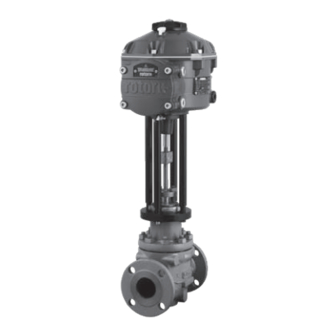
Linear Control Valve Actuator (CVL)
Installation & Maintenance Instructions
Publication P170E Issue 04/09
Advertisement
Table of Contents

Related Manuals for rotork CVL 500


Summary of Contents for rotork CVL 500
- Page 1 Electric Actuators and Control Systems Established Leaders in Valve Actuation This Manual contains important safety information. Please ensure it is thoroughly read and understood before installing, operating or CVL Range maintaining the equipment. Linear Control Valve Actuator (CVL) Installation & Maintenance Instructions Publication P170E Issue 04/09...
-
Page 3: Table Of Contents
With resolution figures better than 0.1% and the ability to • Reduction gearing with linear output shaft. eliminate position overshoot, the Rotork CVA range helps to • Motor controller with speed, travel and thrust limitation. maximize product quality and plant capacity. -
Page 4: General Information
Should further information and guidance relating to the safe and in accordance with all relevant codes of practice for the use of the Rotork Control Valve Actuator Range be required, particular Hazardous Area certification. it will be provided on request. -
Page 5: Hazardous Area Approvals
Hazardous Area Approvals Refer to the actuator nameplate for it’s specific approval details. The CVA is built in accordance with: - European—Hazardous Area ATEX (94/9/EC) II 2 GD c International-Hazardous Area IECEx Ex d IIB T4 Gb, Ex t IIIC T120°C Db Ex d IIB T4 Gb, Ex t IIIC T120°C Db EN60079-0, EN60079-1, EN13463-1, IEC60079-0, IEC60079-1 and IEC61241-1... -
Page 6: Health & Safety
The CVA actuator and in particular the power pack contain no CVL 500 and CVL 1500 actuator castings are manufactured user serviceable components and the top cover assembly from aluminium alloy with stainless steel fasteners. The user must be removed by suitably qualified personnel only. -
Page 7: Storage
CVA distributor. Rotork cannot accept responsibility for deterioration caused on-site once the covers are removed. Every Rotork actuator Unpack the product and information packet taking care to has been fully tested before leaving the factory to give... -
Page 8: Operating Your Cva Actuator
Operating your actuator The following instructions must be followed and integrated WARNING: OPERATING BY HAND with your safety program when installing and using Rotork Where actuators are supplied with the optional hand- Controls products. wheel, note that under no circumstances should any additional lever device such as a wheel key or wrench •... - Page 9 Local Controls The actuator is supplied with a 3 position selector knob located on the top cover assembly. The knob assembly has a locking latch to enable the control knob to be padlocked in position. In the centre of the knob assembly is a tri state LED. Refer to Table 1 for full details of LED indication.
- Page 10 Operating your actuator LED Indication Actuator Status Mode of Operation Solid Green - No Faults Run or Test Note - Electrical operation is not possible whilst the RPP is charging. Green - Slow Flash - Auto Test in progress or Reserve Power Pack (RPP) charging (if fitted).
- Page 11 RESERVE POWER PACK - (OPTIONAL) WARNING The actuator can be fitted with an optional ‘Reserve Power Where actuators are supplied with the reserve Power Pack’ consisting of Super Capacitors to allow the actuator to Pack Assembly please note that the actuator output shaft go to a pre-determined position on power failure.
-
Page 12: Installation & Setup Guide
The height of the yoke or pillar and mounting plate, in relation to the top of the valve spindle is critical to ensure full stroke movement of the valve. Refer to Rotork publication P110E for further details. The Installation & Setup will include the following procedures: Ensure valve is closed and safe (Offline). - Page 13 Quick Setup Flow Chart Establish communication Work Offline with actuator Select Actuator From list Login Select ‘User’ Password ‘sulis’ Stroke Setup Align Coupling Quick Setup Manual Setup Actuator not Wizard fitted Align Coupling Manually set & Auto Setup limits of travel Fit Actuator Valve Actions Input/Output...
-
Page 14: Mounting The Actuator
Installation & Setup Guide Mounting the Actuator Move valve stem to the closed position To enable the actuator to be installed correctly the valve must be in the closed position to allow fitting of the valve stem/ actuator coupling. Actuator Output Shaft The actuator is supplied with the output shaft in the fully retracted position. -
Page 15: Cable Connections
Cable Connections Move the mode selector knob on top of the required actuator to the ‘STOP’ position. This will inhibit electrical operation. WARNING Ensure all power supplies are isolated before removing actuator covers. Check that the supply voltage agrees with that stamped on the actuator nameplate. - Page 16 Installation & Setup Guide Cable entry The cable entries are tapped either ¾” NPT or M25. Remove any plastic transit plugs. Make off cable entries appropriate to the cable type and size. Ensure that threaded adaptors, cable glands or conduit are tight and fully waterproof. Seal unused cable entries with steel or brass threaded plugs.
-
Page 17: Commissioning
Commissioning Move the actuator selector knob to the ’STOP’ position Apply Electrical Power On completion of the correct assembly and electrical connection procedures, the electrical power supply can now be applied to the actuator. NOTE: If the unit is fitted with failsafe capacitors the Green or Red LED (depending on Mode selected) on the selector will flash until the capacitors are fully charged. - Page 18 This password can be changed using the ‘file’ menu to provide additional site security. DO NOT LOSE THE PASSWORD INFORMATION Rotork Engineer Rotork use only. Login Select ‘User ‘ on the User Level drop down menu. Note, user is the default and will appear in the box.
- Page 19 Stroke Setup Menu There are three choices from this menu. Align Coupling If the actuator is not fully fitted to the valve this procedure must be carried out to enable correct assembly and alignment of the actuator coupling to the valve stem. Quick Setup Wizard Use this menu to automatically set actuator limits of travel.
- Page 20 Installation & Setup Guide 1. Set thrust limits The maximum amount of thrust available for the open and close direction of travel can be adjusted by dragging the slider from left to right. 2. Set basic actuator parameters MOV Tag The actuator can be given a TAG number for ease of identification in the field.
- Page 21 Align Coupling It is now possible to operate the actuator using the Enlight program. Moving the position control slider will extend or retract the output shaft to enable it to be connected to the valve spindle. Coarse control will allow full travel of the actuator.
- Page 22 Title Here Installation & Setup Guide Connect the output shaft to the valve spindle using a suitable coupling. It is now possible to set the end of travel limits. Quick Setup Wizard If the valve is to be commissioned over its full stroke the quick setup wizard is a fast and efficient way to set the end of travel limits.
- Page 23 0 pt Move the selector Knob to the ‘RUN’ position CAUTION Initiating an Auto Setup will move the valve through its full stroke. WARNING Steps 1 and 2 must be checked to ensure the thrust, shaft action and end stops are correctly set or damage to the valve may occur.
- Page 24 Installation & Setup Guide The Auto Setup is fully automatic and requires no user input Start Auto Setup? Click on the ‘START’ box to initiate the Auto setup procedure. Click on the OK box to continue. All other menus will be disabled until the process is completed.
- Page 25 0 pt ACTUATOR AUTOMATIC SETUP IS NOW COMPLETE Auto setup is now complete and both ends of travel tight shut off limits have been defined and set. PDA screen will return to the Stroke Set up menu. If no further settings are required move the Mode selector to the ‘STOP’...
- Page 26 Title Here Installation & Setup Guide Manual Setup Flow Chart Establish communication Work Offline with actuator Select Actuator From list Login Select ‘User’ Stroke Setup Align Coupling Quick Setup Manual Setup Actuator not Wizard fitted Align Coupling Manually set & Auto Setup limits of travel Fit Actuator...
- Page 27 The default thrust values for the Manual setup are automatically set to a low value for the commissioning procedure. Open value 40% thrust (200lbf on a CVL 500). Close value 40% thrust. Increase the thrust if necessary. Set Basic Actuator Parameters The MOV tag can be edited by using the keyboard at the bottom of the screen.
- Page 28 Title Here Installation & Setup Guide To Enable electrical operation move the Selector Knob to the RUN position. CAUTION Note the actuator may respond to any present remote control requests during loss of Bluetooth commands or when navigating between screens. It is now possible to move the output shaft to the desired Position using the position control slider.
- Page 29 0 pt Set Open Limit Use the Position Control Slider to move the actuator output shaft to the required Open position. Fig. 31.1 Click on the ‘SET OPEN’ box to calibrate the closed limit of travel. The ‘Set OPEN’ and the ‘Serial’ number boxes are ‘greyed’...
-
Page 30: Diagnostics
Title Here Installation & Setup Guide Configurations Options Setup Flow Chart Establish communication Work Offline with actuator Select Actuator From list Login Select ‘User’ Stroke Setup File Control Diagnostic Setup Save & Load Manual Control Configuration & Test from Actuators &... -
Page 31: The Actuator Comprises
0 pt File From the lower tool bar the menus allow configuration settings to be stored and updated. Load Config from CVA This option will download the actuator configuration of the currently connected actuator to the PDA to allow verification of the settings. - Page 32 Title Here Installation & Setup Guide Save Config to file Save the current actuator configuration to a file location on the PDA. ‘Save config to file’ will open a new screen to save file in PDA. File will be identified by actuator serial number. This can be edited.
- Page 33 0 pt Macro Update ROTORK USE ONLY No USER function. Configuration Settings Further menu options are available from the lower tool bar as follows: Fig. 35.1 Setup Stroke Setup Align Coupling Quick Setup Wizard Manual Setup. Valve Actions Configure thrust output options, direction to close and MOV tag.
- Page 34 Title Here Installation & Setup Guide Valve Actions From the lower tool bar menu select Valve Actions. Fig. 36.1 Fig. 36.2 The following settings are available: Open/Close Thrust Maximum allowed output thrust can be varied between 40% to 100% of rated in both Open and Close directions. The thrust is displayed in lbf or N.
- Page 35 0 pt Input / Output Setup From the lower tool bar select Input/Output Setup. Fig. 37.1 Fig. 37.2 Close Demand mA Calibration Damping Set mA Demand level at fully Closed position. If the actuator responds unnecessarily to a rapidly fluctuating setpoint signal the Damping feature can be used to ‘damp’...
- Page 36 Title Here Installation & Setup Guide Fail Modes From the lower tool bar select Fail Modes. Fig. 38.1 Fig. 38.2 Power Failure Mode (Units fitted with Reserve Power Pack option only). On power failure the actuator can be set to carry out the following actions: Move to Closed limit of travel Move to Open limit of travel...
- Page 37 0 pt Advanced 1 Fig. 39.1 Fig. 39.2 Tight Shut Off Threshold Close Test Knob This box indicates the highest level analogue mA setpoint as The Mode Selector Knob can be disabled to prevent the a percentage that will fully close (tight shut off) the valve. actuator carrying out a pre-determined test routine when the ‘TEST’...
- Page 38 Title Here Installation & Setup Guide Status Relay The actuator has a programmable fault relay that can be set to indicate one of the following conditions shown in Table 3. Mode Description Disabled Always de-energised to reduce power consumption Availability Active when the CVA is capable of being remotely controlled Actuator is in Remote Mode...
- Page 39 0 pt Advanced 2 Fig. 41.1 Fig. 41.2 Direction Change Threshold Distance Bumpless Transfer Distance (BTD) The distance the actuator must move before a direction The bumpless transfer distance is a pre defined percentage change is registered by the datalogger as a cycle. of position error that will reduce the actuator speed to a pre-determined speed.
- Page 40 Title Here Installation & Setup Guide Characterization The actuator relationship between the Demand Request and the Demand Signal is Linear by default. Use the Valve Characteristic drop down menu to select between the following: Fig. 42.1 Linear The actuator position responds directly to the mA demand request.
- Page 41 0 pt Equal Percentage The change in actuator position is directly proportional to the demand request. Fig. 43.1 Valve Position & Demand Signal The position against demand profile can be tailored to suit the valve application by plotting the characteristic at up to 20 co-ordinate points on the graph.
- Page 42 Note: If the actuator Password is changed it will not be possible to communicate with the unit, unless the correct password is used. DO NOT LOSE THE PASSWORD INFORMATION. CONTACT ROTORK IN CASE OF LOST PASSWORD INFORMATION. Fig. 44.2 Note Engineer 1 Fig.
- Page 43 0 pt Control & Diagnostics Options Setup Flow Chart Login Select ‘User’ Establish communication Work Offline with actuator Select Actuator From list Stroke Setup File Control Diagnostic Setup Save & Load Manual Control Configuration & Test from Actuators & Files Valve Actions Input/Output Fail Modes...
- Page 44 Rated Speed Output shaft speed is variable between 5% and 100% of rated speed. Thrust The output thrust is a live indication of mechanical effort required during valve travel. Fig. 46.2 Note Run Test is a Rotork only function. Fig. 46.3...
- Page 45 0 pt Diagnostic Menus Datalogger The data logger function is used to download historical data from the actuator for review on a PDA or PC. Fig. 47.1 Fig. 47.2 The data logger page graph can display open / close thrust and dwell time.
- Page 46 Title Here Installation & Setup Guide Status Active alarms and status are displayed. Fig. 48.1 Fig. 48.2 Reference stroke When the actuator has been commissioned it is possible to set a reference stroke to record thrust. This can be compared against a current recording to determine if any parameters have changed.
- Page 47 0 pt Compare If a configuration file has previously been saved it can be compared to the current settings. Fig. 49.1 Fig. 49.2 When the compare screen appears click onto the compare box and you will be prompted to find a previously stored configuration file.
- Page 48 Title Here Installation & Setup Guide Manufacture Data Display manufacturing data including software version and serial numbers. Fig. 50.1 Fig. 50.2...
- Page 49 0 pt Rotork Sales and Service If your Rotork actuator has been correctly installed and sealed, it will give years of trouble-free service. Should you require technical assistance or spares, Rotork guarantees the best service in the world. Contact your local Rotork representative or the factory direct at the address on the nameplate, quoting the actuator type and serial number.
- Page 50 As part of a process of on-going product development, Rotork reserves the right to amend and change specifications without prior notice. Published data may be subject to change. For the very latest version release, visit our website at www.rotork.com The name Rotork is a registered trademark. Rotork recognises all registered trademarks.
Need help?
Do you have a question about the CVL 500 and is the answer not in the manual?
Questions and answers