
Subscribe to Our Youtube Channel
Related Manuals for rotork CML Series


Summary of Contents for rotork CML Series
- Page 1 Range CML1500 and CML 3000 Installation & Maintenance Instructions Linear Control Valve Actuators...
-
Page 2: Table Of Contents
Contents Introduction Basic Setup Basic Setup General Information Basic Menu Structure Introduction Enclosure Materials Basic Setup Flowchart General Actuator Description Select Local Operation Receiving / Inspection Set Output Thrust Storage Select Action at End of Travel Equipment Return Set Closed Limit of Travel Abbreviations used in this Manual Set Open Limit of Travel Warranty Information... -
Page 3: Introduction
The following instructions must be followed and integrated specified by Rotork. Substitutions may result in fire, with your safety program when installing and using Rotork electrical shock, other hazards, or improper equipment products: operation •... -
Page 4: General Information
Should further information and guidance relating to the safe and in accordance with all relevant codes of practice for the use of the Rotork control valve actuator range be required, it particular Hazardous Area certification. will be provided on request. -
Page 5: General Actuator Description
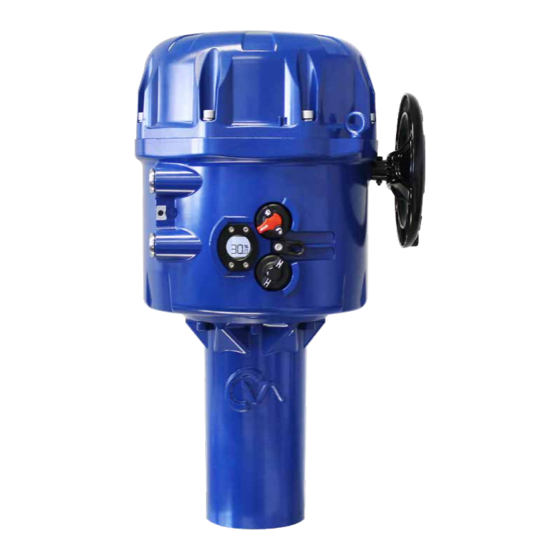
2.3.1 CML - Linear The CML range of actuators are high precision linear Building on Rotork’s historical success with innovative actuators capable of producing a modulating thrust from 100 technology, the CMA offers a highly accurate and responsive to 3000 pounds force (13.35 kN) depending on model size. -
Page 6: Receiving / Inspection
(1) year from the date of delivery. The foregoing is the sole and Protection provided by the equipment may be exclusive warranty made by Rotork with respect to the products. impaired if used in a manner not specified by Rotork. -
Page 7: Approvals
Rotork. The limits of frequency of operation are a function of the load CMA Range actuators are built in accordance with the on the actuator and the ambient temperature. -
Page 8: Environmental Conditions
Approvals Environmental Conditions a) Altitude up to 5000 meters CMA adheres to requirements consistent with Overvoltage Category II c) The CMA adheres to the requirements consistent with a Pollution Degree of 2 Special Conditions For Safe Use (FMC, ATEX & IECEx approved actuators) In accordance with clause 5.1 of IEC/EN 60079-1, the critical dimensions of the flamepaths are: CML-1500/3000 Flamepath... -
Page 9: Health & Safety
Actuators supplied with the Reserve Power Pack (RPP) the intended application. If you are unsure of the suitability may move when the power supply is removed. of this equipment for your installation consult Rotork prior to installation. Do not remove the actuator top cover whilst the position display is illuminated and/or flashing. -
Page 10: Actuator Identification
Actuator Identification Outside the Actuator 5.1.1 Local Controls & External LCD Display Actuators are supplied with local controls and an external backlit display. Selecting Local/Stop/Remote Operation The red and black selector determines operating mode as LOCAL, STOP or REMOTE. This can be locked in place with a 6.5mm hasp padlock. -
Page 11: Inside The Actuator
Actuator Identification Inside the Actuator 5.2.1 User Interface Configuration of setting parameters is performed via the internal user interface. The user interface comprises LCD display and push buttons. Fig 5.4 Internal interface 5.2.2 Terminal Block Connections for the power, control and indication wiring are provided by terminal blocks fitted to the top side of the electrical chassis. - Page 12 Actuator Identification 5.2.3 LCD Display LOCAL The user interface has a LCD Display that shows STATUS and configuration information. POS I T The default screen is the POSIT parameter. The active operating mode, LOCAL or REMOTE, is shown in the top left corner of the LCD. Fig 5.6 LCD display 5.2.4 Setup Pushbuttons...
-
Page 13: Installation
Tools & Equipment Required (General Guideline Only) Top Cover Fixings - 8 mm Allen Wrench The following instructions must be followed and integrated into your safety program when installing and using Rotork Electrical Connections - Terminal Screw Driver products. - Power Supply •... -
Page 14: Mounting The Actuator
Installation Mounting the Actuator CAUTION It is essential that the actuator mounting procedure is carried out when the valve is not under working process conditions, as full valve movement may occur. IMPORTANT It is essential that the actuator is mounted correctly to the valve. - Page 15 Installation Move Valve stem to the closed position To enable the actuator to be installed correctly the valve must be in the closed (down) position to allow fitting of the valve stem/actuator coupling. Fig 6.2 Valve shaft Actuator Output Shaft The actuator is supplied with the output shaft in the fully retracted position.
- Page 16 Installation Extend the actuator output shaft to bring the end of the shaft and the coupling together. Rotate the coupling as required to get a good firm contact between the valve stem and the output shaft. Fig 6.5 Mounting flange Adjust and tighten locking nut(s) if fitted on valve stem side of the coupling.
-
Page 17: Electrical Installation
Installation Electrical Installation 6.3.1 Cable Entries The 4 cable entries are tapped either ¾” NPT or M25. Remove any transit plugs. Make off cable entries appropriate to the cable type and size. Ensure that threaded adaptors, cable glands or conduit are tight and fully waterproof. Seal unused cable entries with steel or brass threaded plugs. - Page 18 Installation 6.3.4 Earth Ground Connections A lug is cast adjacent to the conduit entries for attachment of an external protective Earth (Ground) cable. An internal earth terminal is also provided. Consult local and certifying agency codes to determine which earth connections must be used. Refer to Fig 6.10.
- Page 19 50 Hz / 60 Hz Fig 6.16 Wiring installation 24 VDC Only Supply voltage fluctuations not to exceed +/- 10% of the nominal supply voltage. ROTORK PROCESS CONTROLS www. .com MILWAUKEE, WI, USA. Supply frequency tolerance +/- 10%. Serial number...
-
Page 20: Basic Setup
Basic Setup Basic Setup LOCAL Basic setup is required once the actuator has been mounted on to the valve. POS I T Procedures include: Step 1 Select Local Operation Step 2 Set Output Thrust Step 3 Select Action at End of Travel ( Limit or Force) Step 4 Set Close Limit of Travel Step 5... -
Page 21: Basic Menu Structure
Basic Setup Basic Menu Structure Basic Setup Flowchart BASIC STEP 1 SELECT LOCAL OPERATION POSIT POSITION Position SET PT SETPOINT Setpoint STEP 2 SET OUTPUT THRUST THRUST THRUST Thrust Display LOCREM LOCAL/REMOTE OPERATION Local / Remote Operation STEP 3 MANJOG SELECT ACTION AT END MANJOG Manual Jog... -
Page 22: Select Local Operation
Basic Setup STEP 1 SELECT LOCAL OPERATION Select Local Operation STEP 2 The LOCAL/STOP/REMOTE selector determines the actuator SET OUTPUT THRUST operating mode at all times. LOCAL mode must be active in order to edit and save configuration parameters. STEP 3 SELECT ACTION AT END OF TRAVEL (LIMIT OR FORCE) STEP 4... -
Page 23: Set Output Thrust
STEP 1 Basic Setup SELECT LOCAL OPERATION STEP 2 SET OUTPUT THRUST LOCAL Set Output Thrust STEP 3 THRSTC SELECT ACTION AT END OF TRAVEL (LIMIT OR FORCE) Before operating the actuator electrically it may be necessary to reduce the output thrust of the actuator to prevent valve becoming jammed at the end of travel during setup. - Page 24 Basic Setup Set Output Thrust (cont'd) If the Close Thrust value requires adjustment LOCAL press ENTER. E D I T TC 600 The actuator is now in EDIT Mode and the parameters can be modified. Fig 7.8 Edit close thrust value Use the UP/DOWN buttons until the correct Thrust Value is displayed.
-
Page 25: Select Action At End Of Travel
Basic Setup Set Output Thrust (cont'd) LOCAL E D I T TO 100 The actuator is now in EDIT Mode and the parameters can be modified. Use the UP/DOWN buttons until the correct Thrust value Is displayed. Fig 7.13 Edit open thrust value Press ENTER to save the changes. - Page 26 Basic Setup Select Action at End of Travel (cont'd) LOCAL VIEW CA LIM CA LIM shows the actuator is set for Position Limit action at the Closed end of travel. Fig 7.17 View close action value To change the end of travel action press ENTER. The actuator is now in EDIT Mode.
-
Page 27: Set Closed Limit Of Travel
STEP 2 SET OUTPUT THRUST STEP 3 Basic Setup SELECT ACTION AT END OF TRAVEL (LIMIT OR FORCE) STEP 4 SET CLOSE LIMIT OF TRAVEL Set Closed Limit of Travel LOCAL STEP 5 SET OPEN LIMIT MANJOG OF TRAVEL STEP 6 CALIBRATE COMMAND SIGNAL ZERO SETPOINT Fig 7.23... -
Page 28: Set Open Limit Of Travel
STEP 3 SELECT ACTION AT END OF TRAVEL (LIMIT OR FORCE) STEP 4 Basic Setup SET CLOSE LIMIT OF TRAVEL LOCAL STEP 5 SET OPEN LIMIT OF TRAVEL CL L I M Set Open Limit of Travel STEP 6 Press the DOWN arrow until the OP LIM menu is displayed. CALIBRATE COMMAND SIGNAL ZERO SETPOINT Fig 7.27... -
Page 29: Calibrate Command Signal Zero Setpoint
STEP 4 SET CLOSE LIMIT OF TRAVEL STEP 5 Basic Setup SET OPEN LIMIT OF TRAVEL STEP 6 CALIBRATE COMMAND SIGNAL ZERO SETPOINT Calibrate Command Signal Zero Setpoint STEP 7 After the open/close limit is set the 4 to 20 mA signal is CALIBRATE COMMAND SIGNAL SPAN SETPOINT automatically calibrated to those positions. - Page 30 STEP 4 SET CLOSE LIMIT OF TRAVEL STEP 5 Basic Setup SET OPEN LIMIT OF TRAVEL LOCAL STEP 6 CALIBRATE COMMAND SIGNAL ZERO SETPOINT POS I T 7.9.2 Calibrate Command Signal Zero Setpoint Using an External 4-20 mA Signal STEP 7 CALIBRATE COMMAND SIGNAL SPAN SETPOINT Fig 7.33...
- Page 31 STEP 5 SET OPEN LIMIT OF TRAVEL STEP 6 Basic Setup CALIBRATE COMMAND SIGNAL ZERO SETPOINT LOCAL STEP 7 CALIBRATE COMMAND SIGNAL SPAN SETPOINT POS I T 7.9.3 Calibrate Command Signal Span Setpoint Using an External 4-20 mA SIGNAL STEP 8 DEADBAND Fig 7.38 Default display...
-
Page 32: Set Deadband
STEP 6 CALIBRATE COMMAND SIGNAL ZERO SETPOINT STEP 7 Basic Setup CALIBRATE COMMAND SIGNAL SPAN SETPOINT LOCAL STEP 8 DEADBAND POS I T 7.10 Set Deadband Press the DOWN arrow until the DBAND menu is displayed. Fig 7.43 Default display LOCAL DBAND Press ENTER until ‘EDIT’... -
Page 33: Completing Basic Setup
Basic Setup 7.11 Completing Basic Setup Ensure that the spigot face is clean and greased with the o-ring seal fitted and in good condition. Fig 7.48 Cover spigot face Carefully align the top cover. Ensure that all wiring is fitted correctly and will not foul the top cover once fitted. -
Page 34: Menu Structure
Basic Setup 7.12 Menu Structure CMDSRC INFO CTRCFG BASIC ADVANC PRM OC ST ACT CTRLAL POSIT Primary Option CPT 4 Position RI CTL AMP ST IN DMP Remote Control Inputs SET PT CPT 20 2W PRI TEMP Setpoint LOS TO 2 Wire Priority LOS AC THRUST... -
Page 35: Status Alarm Menu
RELAYS LOS HI OP LIM Open Limit (span) Control Setup RLY1 CFG TORQ O CMD4 RELAYS RLY1 POS Field Command Signal4 TORQ C RLY1 FRM CMD20 SPLT RANGE CL ACT Field Command Signal20 Status Alarm Menu RLY2 CFG DBAND ACT CFG OP ACT RLY2 POS Deadband... - Page 36 EF FLT - EEPROM Factory Defaults Actuator runs. Cycle power to remove the alarm. If problem ESD - Emergency Shutdown active persists contact Rotork. Emergency Shut Down (ESD) command is active. The actuator will not respond to any other commands until the ESD condition is removed.
-
Page 37: Fault History Menu
CMD4 RELAYS RLY1 POS Field Command Signal4 TORQ C RLY1 FRM CMD20 SPLT RANGE CL ACT Field Command Signal20 RLY2 CFG DBAND ACT CFG OP ACT RLY2 POS Deadband Fault History Menu STATUS RLY2 FRM ACT CFG ACT TYPE LOCAL FLTHST Fault History Access ACT SIZE... - Page 38 EEPROM Fault, factory An error occurred when the Factory defaults were stored. The actuator will still run but the Factory defaults should be checked and resaved. Cycling the power will clear the fault, contact Rotork if the problem persists. Reset The actuator was reset (power cycled).
-
Page 39: Default Menu
DBAND ACT CFG OP ACT RLY2 POS Deadband STATUS RLY2 FRM ACT CFG ACT TYPE FLTHST Fault History Access 10.0 Default Menu ACT SIZE ADVANC SP RANGE Advanced Menu ENCOD IN MIN CMD LOCAL DEFLTS DEFAULTS Default Menu Access MAX CMD DEFLTS 10.1 Default Menus LD CUST... -
Page 40: Parameter Default Values
10.0 Default Menu 10.2 Parameter Default Values 10.2.1 Basic Menu PARAMETER DEFAULT VALUE Position No default setting is a read parameter Setpoint No default setting is a read parameter Thrust No default setting is a read parameter Local/Remote LOC - local Manual Jog No default setting is a control Close Limit (zero) - Page 41 10.0 Default Menu 10.2.4 Control Configuration Menu PARAMETER DEFAULT VALUE Control Algorithm Open loop Input Dampening 0 seconds Input Signal Loss Time out 0 seconds Input Signal Loss Action Close Input Signal Loss Position Input Signal Loss Low Level 3.6 mA Input Signal Loss High Level 20.4 mA TORQ O...
-
Page 42: Advanced Menu
11.0 Advanced Menu 11.1 Advanced Menu Access CMDSRC INFO CTRCFG BASIC ADVANC PRM OC ST ACT CTRLAL POSIT Primary Option CPT 4 Position RI CTL AMP ST IN DMP Remote Control Inputs SET PT CPT 20 2W PRI TEMP Setpoint LOS TO 2 Wire Priority LOS AC... -
Page 43: Advanced Menu
11.0 Advanced Menu ADVANC CMDSRC INFO CTRCFG ADVANCED SETTINGS BASIC ADVANC 11.2 Advanced Menu PRM OC ST ACT CPT 4 - Current POS CTRLAL POSIT Primary Option CPT 4 Transmitter - Zero/4 ma Position Parameters can only be changed with actuator selected to RI CTL AMP ST IN DMP... - Page 44 11.0 Advanced Menu CMDSRC COMMAND SOURCE CMDSRC INFO BASIC ADVANC PRM OC 11.2.5 CMDSRC - Command Source Primary Option Selection ST ACT POSIT Primary Option CPT 4 Select between Analogue, Digital or Bus Remote Commands. Position RI CTL AMP ST Remote Input Control Selection Remote Control Inputs SET PT...
- Page 45 11.0 Advanced Menu CMDSRC INFO CTRCFG - Control Setup CTRCFG CMDSRC INFO CTRCFG INFORMATION ADVANC BASIC ADVANC PRM OC PRM OC ST ACT - ACTUATOR STARTS ST ACT ST ACT CTRLAL - Control Algorithm CTRLAL CTRLAL POSIT Primary Option Primary Option CPT 4 CPT 4 Position...
- Page 46 RIRO Only LOS LO TURNS*** LOCREM ESDACT Local / Remote Operation ESD Action LOS HI OP DIR*** ESDOLS MANJOG ESD Override Local Stop Manual Jog KNBMNT STL TO Local Maint TORQ/THRSTC 11.0 Advanced Menu Close Torque/Thrust CMD SRCE CMDSRC TORQ/THRSTO Open Torque/Thrust INFO CL ACT...
- Page 47 ESDACT Local / Remote Operation ESD Action LOS HI OP DIR*** ESDOLS MANJOG ESD Override Local Stop Manual Jog STL TO KNBMNT Local Maint TORQ/THRSTC Close Torque/Thrust CMD SRCE CMDSRC 11.0 Advanced Menu TORQ/THRSTO Open Torque/Thrust INFO CL ACT RELAYS Close Action CTRCFG DIG IN...
- Page 48 D2 CFG R2 CFG MAXCMD SPLTRG D2 FRM R2 POS BSRACT D3 CFG R2 FRM ACT CFG BSRPOS D3 FRM R5 CFG al20 COMMS 11.0 Advanced Menu ASRACT D4 CFG R5 POS ASPOS D4 FRM R5 FRM ACTCFG - ACTUATOR CONFIGURATION ACTCFG R6 CFG INTTIM...
- Page 49 11.0 Advanced Menu TIMER INTERRUPT INTTIM INTTIM CL TIE - Closed-end Timer Interrupt Enable 11.2.13 INTTIM - Timer Interrupt CL TIE The timer interrupt function enables pulsed "stop/start" ST CLS - Start Close ST CLS operation by the actuator as a response to local and remote control commands.
- Page 50 11.0 Advanced Menu FOLOMATIC COMMS COMMS F RANGE Select mA or voltage (5 V or 10 V) 11.2.14 COMMS - Bus Option Card MOD BD type signal Configuration FCAL L Calibrate Low signal setpoint MOD FT Apply low input analogue signal The following menus appear automatically MOD AD and save setting...
-
Page 51: Maintenance
12.0 Maintenance Routine maintenance should include the following: • Check actuator to valve fixings bolts for tightness • Ensure valve stems and drive shafts are clean and properly lubricated • If the motorized valve is rarely operated, a schedule of operation should be set up and adhered too •... - Page 52 Original instructions: English language version only. As part of a process of on-going product development, Rotork reserves the right to amend and change specifications without prior notice. Published data may be subject to change. For the very latest version release, visit our website at www.rotork.com PUB094-019-00 The name Rotork is a registered trademark.
Need help?
Do you have a question about the CML Series and is the answer not in the manual?
Questions and answers