Table of Contents
Advertisement
Quick Links
Advertisement
Table of Contents

Related Manuals for ETAS ES1336.1


Summary of Contents for ETAS ES1336.1
- Page 1 ES1336.1 Angle Synchronous Measurement Board User’s Guide...
- Page 2 Copyright The data in this document may not be altered or amended without special notification from ETAS GmbH. ETAS GmbH undertakes no further obligation in relation to this document. The software described in it can only be used if the customer is in possession of a general license agreement or single license.
-
Page 3: Table Of Contents
Contents 1 Introduction ........... . . 5 Applications . - Page 4 6 ETAS Contact Addresses........
-
Page 5: Introduction
The components, connectors and conductors of the ES1336.1 Angle Synchronous Measurement Board may carry dangerous voltages. These voltages may even exist when the ES1336.1 is not installed in the ES4100, ES4105 or ES4300 or the ES4100, ES4105 or ES4300 is powered off. -
Page 6: Applications
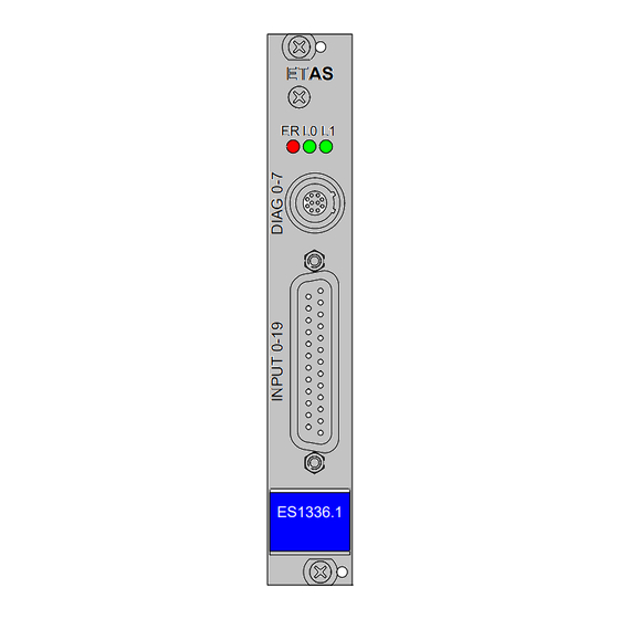
Applications The ES1336.1 Angle Synchronous Measurement Board is used to acquire and evaluate digital ECU signals. This means: • The acquisition and evaluation of speed-synchronous (= angle-synchro- nous) signals such as injection and ignition signals. • The acquisition and evaluation of asynchronous (usually pulse-width modulated) signals such as exhaust gas recirculation and canister purge valve. - Page 7 The following figure shows the front panel of the ES1336.1 Angle Synchro- nous Measurement Board. ETAS ES1336.1 Fig. 1-1 Front Panel of the ES1336.1 Angle Synchronous Measurement Board Introduction...
-
Page 8: Block Diagram
Block Diagram Fig. 1-2 shows the block diagram of the ES1336.1 Angle Synchronous Mea- surement Board. Edge Diagnostic Processor Recognition Outputs (FPGA) (FPGA) Overvoltage Impedance Serial Protection Converter Converter Flash CH19 CH19 CH19 Fig. 1-2 Block Diagram of the ES1336.1 Angle Synchronous Measure-... -
Page 9: Taking The Product Back And Recycling
The user is obliged to collect the old devices separately and return them to the WEEE take-back system for recycling. The WEEE directive concerns all ETAS devices but not external cables or batter- ies. For more information on the ETAS GmbH Recycling Program, contact the ETAS sales and service locations (see "ETAS Contact Addresses"... - Page 10 Introduction...
-
Page 11: Hardware
Hardware This chapter describes the individual function units of the ES1336.1 Angle Syn- chronous Measurement Board in more detail. These are: • "Signal Inputs" on page 11 • "Synchronization Signals" on page 13 • "Angle Windows" on page 13 •... -
Page 12: Threshold Comparison
2.1.3 Threshold Comparison Each of the 20 input signals of the ES1336.1 Angle Synchronous Measurement Board is compared to two threshold values in the FPGA. This comparison leads to a conversion of the analog input signal to digital 0/1 information. -
Page 13: Synchronization Signals
The ES1336.1 Angle Synchronous Measurement Board can also be used as master, i.e. it issues the angle clock signal on the VME backplane. The defini- tion of whether the particular ES1336.1 works as an angle clock master or slave is made in LABCAR-RTC (RTIO). - Page 14 Calculating the Measure Values The measure values start being calculated once the upper end of the angle window has been reached; the result is transferred directly to the DPRAM. This ensures that the data in the DPRAM is up-to-date and consistent. Fig.
-
Page 15: Diagnostic Outputs
• Angle clock synchronization signal (0 °CA trigger signal, see Fig. 2-3 on page 13) ETAS can supply a corresponding cable with eight BNC connectors (for output- ting the signals, for example on an oscilloscope) (see "Accessories" on page 23). - Page 16 • Lowtime using L-Validate [μs] Frequency and Cycle Time Measurements • Frequency --/-- [Hz] • Cycle Time --/-- [μs] Duty Cycle Measurements • Duty Cycle L/(L+H) --/-- • Duty Cycle H/(L+H) --/-- Measuring Edges: Angle Stamp • Rising Edge --/-- [deg] •...
-
Page 17: Start Of Angle Measuring After Initialization
Start of Angle Measuring after Initialization The ES1336.1 needs three camshaft revolutions after initialization until it is synchronized with the ES1335 Arbitrary Signal Generator Board. No measure values are issued during this time. Initialization is executed: • after downloading the model code to the simulation target •... - Page 18 Hardware...
-
Page 19: Pin Assignment And Display Elements
Pin Assignment and Display Elements This chapter contains a description of the pins and LEDs on the front panel of the ES1336.1 Angle Synchronous Measurement Board. “Input 0-19” Connector The input signals and battery voltages are applied at the “Input 0-19” connec- tor. -
Page 20: Diag 0-7" Connector
“DIAG 0-7” Connector Up to 8 FPGA signals can be led through to the “DIAG 0-7” connector for diagnostic purposes. The connector is a Lemo EXB.1B.310.HLN (female) connector. Fig. 3-2 shows the pin assignment (view from the plug-in side). Fig. 3-2 “DIAG 0-7”... -
Page 21: Leds For Status Display
LEDs for Status Display There are three LEDs on the front panel of the ES1336.1 Angle Synchronous Measurement Board. Fig. 3-3 LEDs on the Front Panel The LEDs have the following meaning: Display Meaning Showing red Error (e.g. ROM data damaged, card not cali-... - Page 22 Pin Assignment and Display Elements...
-
Page 23: Accessories
Accessories Digital Output Cable with BNC There is a special cable available from ETAS, the CBAV245, to connect the output signals at the diagnostic port “DIAG 0-7” to, for example, an oscillo- scope. OUTPUT CH1 OUTPUT CH2 OUTPUT CH3 OUTPUT CH4 CBAV245.1-2... - Page 24 Accessories...
-
Page 25: Technical Data
Technical Data This chapter contains the technical data on the ES1336.1 Angle Synchronous Measurement Board. Digital Inputs Number of channels Input voltage range 0 V ... 40 V Input impedance 1 MΩ Electric strength ±60 V Accuracy of voltage measurement ±80 mV... - Page 26 Inputs for Battery Voltages Number of channels Input voltage range 0 V … 60 V Electric strength ±60 V Diagnostic Output Number of channels Output voltage Output current 5 mA Electric strength ±60 V Max. output frequency 1 MHz Environmental Conditions Operating temperature 5 °C to 35 °C (41 °F to 95 °F) Relative humidity...
-
Page 27: Etas Contact Addresses
Germany WWW: www.etas.com ETAS Subsidiaries and Technical Support For details of your local sales office as well as your local technical support team and product hotlines, take a look at the ETAS website: ETAS subsidiaries WWW: www.etas.com/en/contact.php ETAS technical support WWW: www.etas.com/en/hotlines.php... - Page 28 ETAS Contact Addresses...
-
Page 29: Index
Cable Initialization 17 for diagnostic outputs 23 Input circuitry 11 Connectors Introduction 5 “DIAG 0-7” 20 “Input 0-19” 19 LEDs 21 Diagnostic outputs 15 cable 23 Measurement modes 15 Electrical strength 11 Product Back 9 ETAS Contact Addresses 27 Index... - Page 30 Recycling 9 Shielding 12 Signal inputs 11 Status display 21 Synchronization signals 13 Technical Data 25 Threshold comparison 12 Waste Electrical and Electronic Equipment 9 Index...
Need help?
Do you have a question about the ES1336.1 and is the answer not in the manual?
Questions and answers