Table of Contents
Advertisement
Quick Links
Advertisement
Chapters
Table of Contents

Subscribe to Our Youtube Channel
Related Manuals for ETAS ES341.1


Summary of Contents for ETAS ES341.1
- Page 1 ES341.1 Counter and Frequency Module with Sensor Supply (4 CH) User’s Guide...
- Page 2 The data in this document may not be altered or amended without special noti- fication from ETAS GmbH. ETAS GmbH undertakes no further obligation in rela- tion to this document. The software described in it can only be used if the customer is in possession of a general license agreement or single license.
-
Page 3: Table Of Contents
Sensor Supply ........19 ES341.1 - User’s Guide... - Page 4 Ambient Conditions ........41 ES341.1 - User’s Guide...
- Page 5 11 ETAS Contact Addresses ........
-
Page 6: About This Manual
(serious) injury, if not avoided. CAUTION! identifies a hazard with low risk that could result in minor or medium physical injuries or property damages if not avoided. ES341.1 - User’s Guide... -
Page 7: Presentation Of Information
(see chapter 10 on page 52). Additional cables and adapters can be obtained separately from ETAS. A list of available accessories and their order designation is located in chapter "Ordering Information" on page 52 of this manual or in the ETAS product catalog. -
Page 8: Basic Safety Notices
• "Requirements for Users and Duties for Operators" on page 8 • "Intended Use" on page 8. General Safety Information Please observe the Product Safety Notices ("ETAS Safety Notice") and the follow- ing safety notices to avoid health issues or damage to the device. Note Carefully read the documentation (Product Safety Advice and this User's Guide) that belongs to the product prior to the startup. - Page 9 • The lab power supply must be approved for an operating altitude of 3,000 m / 9,842 ft. and for an ambient temperature of up to 105 °C. • The vehicle battery could be discharged when the modules are in opera- tion. ES341.1 - User’s Guide...
- Page 10 Connecting to a mains socket is not allowed! To prevent the connector from accidentally being plugged into a mains socket, ETAS recommends using power supply cables with safety banana plugs in areas with mains sockets.. De-energizing the module The module does not have a power switch.
- Page 11 • Use exclusively ETAS cables at the connections of the module! • Adhere to the maximum permissible cable lengths! • Do not use any damaged cables! Cables may be repaired only by ETAS! CAUTION! Never apply force to insert a plug into a socket.
- Page 12 Maintenance The product is maintenance-free. Repair If an ETAS hardware product should require a repair, return the product to ETAS. Cleaning the module housing • Use a dry or lightly moistened, soft, lint-free cloth for cleaning the module housing.
-
Page 13: Es300 Product Family
This causes long setup times and high costs. With the ES300 modules, ETAS offers a decentral solution that significantly sim- plifies the measuring set-up of the sensors. The basic idea of this concept is to install the modules of the ES300 series spa- tially as close as possible to the sensors, to chain the modules with each other and to connect only the first module of this chain with the laptop in the vehicle. -
Page 14: Additional Properties
• All channels fully electrically isolated • Dovetailing for tool-free module connection of the ES300 modules • Different channel sampling rates • Part of the ETAS Tool Suite The complete technical data is located in chapter 8 on page 40. ES341.1 - User’s Guide... -
Page 15: Hardware Description
• Status LED at every measuring input (signal recording display) • Measuring data output to CAN • Designed for direct installation in the engine compartment • Tool-free connection technology The complete technical data of the ES341.1 is located in chapter 8 on page 40. ES341.1 - User’s Guide... -
Page 16: Housing
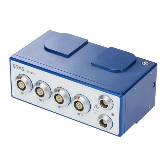
ETAS Housing The ES341.1 utilizes a robust metal housing with connections at the front of the unit. The ES341.1 is designed for installation in the engine compartment. The housings of the ES300 series can be connected with each other quickly and easily to form a measuring system (see chapter 6 on page 25). -
Page 17: Leds
ES300 series or the CAN terminat- ing resistor is connected to the connection at the last module of the chain. LEDs The ES341.1 features a status LED for the display of the operating state. LED code Display... -
Page 18: Functional Description
Sensor Connections 5.1.1 Properties All sensor connections of ES341.1 feature identical designs. They consist of an input stage with signal recording and signal processing. Configurable hysteresis The hysteresis and the corresponding values for the levels LOW and HIGH can be... -
Page 19: Sensor Supply
ETAS Functional Description Inverter The input signal of each channel of the ES341.1 can be inverted as needed, inde- pendent of the other channels. The selection is done in the application software. Signal recording and signal processing In this function group, the input signal is sampled and processed according to the measurement function selected in the application software. -
Page 20: Period Duration
The two modes frequency counter and event counter with detection of direction can be adjusted for the channels 1/2 and 3/4. This enables incremental encoders with phase-shifted second output signal to be used for detection of rotation or count direction. ES341.1 - User’s Guide... -
Page 21: Data Transmission
End of Frame For each CAN message, a maximum of 4 measured values can be transmitted in word format or a maximum of 8 measured values in byte format. Word Byte Bit (message layout in "Intel-Std" representation format) ES341.1 - User’s Guide... -
Page 22: Properties
ES300 modules. The master clock pulse is set via the software (see also 8 on page 40). As a result, one module is designated as clock generator. The remaining modules accept this clock pulse. ES341.1 - User’s Guide... -
Page 23: Power Supply
5.4.1 Supply Voltage DC/DC converter in every module guarantee the operation as well as the start of ES341.1 for supply voltages between 10 and 33 VDC across the entire tempera- ture range. 5.4.2 Supply of the ES300 Modules via Connecting Line In the simplest application case, the modules are directly chained. -
Page 24: Configuration
During a firmware update, neither the voltage supply nor the CAN connection may be interrupted! Calibration A calibrating service is available for your ES341.1. To ensure a reliable accuracy of the measured values, the ES341.1 should be calibrated every year. Information about the last calibration is stored at the device. -
Page 25: Commissioning
CAUTION! Damage or destruction of module is possible. The ES341.1 is approved only for the assembly and operation on components or at locations that ensure that the technical data of the module is being maintained during operation (see chapter 8 on page 40). -
Page 26: Assembly
Additional parts are required for the assembly of the modules (screws or threaded rods with nuts, cable ties, etc.) Note The ES341.1 can be connected mechanically with other ES300 modules with dovetailing without any additional parts. Knockouts for cable ties... - Page 27 2 bores on the rear side. Knockouts for cable ties Both sides of the ES341.1 feature 1 knockout each to the rear side of the module for fastening to other components using cable ties.
-
Page 28: Applications
Fig. 6-3 ES300 modules and additional ETAS modules for MC applications The daisy-chain concept enables a simple network architecture since only the ES341.1 or the first module of the module chain must be connected with the bus interface module. Cabling The order of the cabling of the connections is random. -
Page 29: Daisy-Chain Connections
2. Connect the CAN connecting cable with the con- nector of the ES341.1 of the last module of the chain in the direction of the PC. 3. Connect the CAN connecting cable with the con- nector of the module that is next in the direction of the cable end. -
Page 30: Software Description
To configure ES300 modules, they must either be added to a workspace in advance or be able to be detected by the IPEaddon. Note Please refer to the INCA User's Guide for information on how to add modules to a hardware environment. ES341.1 - User’s Guide... -
Page 31: Functions
Note The CAN bus of the ES3xx modules supports a fixed baud rate of 500 kBd. A module cannot be detected with a different baud rate. It is also not possible to change the baud rate. ES341.1 - User’s Guide... -
Page 32: Initialization
5.3.4 on page 22). Configuring the synchronization mode 1. Select Hardware Options in the menu bar. The IPETRONIK / ETAS: Options window appears. 2. Select the CAN interfaces tab. 3. In the CAN device synchronization mode section select one of the two Free-running or synchro- nous modes. - Page 33 The configuration of the modules is overwritten with the respective standard configuration. Initializing standard values 1. Select Hardware Default init in the menu bar. The initialization of the standard values starts. Once the initialization process is complete, the modules are reset to the default values. ES341.1 - User’s Guide...
-
Page 34: Setting Up Aliasing Filters
ETAS 7.4.3 Setting Up Aliasing Filters Setting up aliasing filters 1. Select Hardware Options in the menu bar. The IPETRONIK / ETAS: Options window appears. 2. Select the Options tab. 3. Activate/deactivate the option Aliasing-free filter settings. Fig. 7-3 Setting up aliasing filters 4. -
Page 35: Fig. 7-4 Module Configuration Context Menu
Module configuration context menu 2. Select the Column Chooser entry. The Customization window appears with the selection of all available columns. Fig. 7-5 Module configuration column selection 3. Select one or more columns by double-clicking on them. ES341.1 - User’s Guide... -
Page 36: Configuring A Channel
Channel configuration context menu 2. Select the Column Chooser entry. The Customization window appears with the selection of all available columns. Fig. 7-7 Module configuration column selection 3. Select one or more columns by double-clicking on them. ES341.1 - User’s Guide... -
Page 37: Adjustment
7.4.6 Adjustment Offset adjustment You can use the offset adjustment to set up measuring devices to eliminate known systematic deviations for the intended application. In contrast to calibra- tion, changes to the offset adjustment are permanent. ES341.1 - User’s Guide... -
Page 38: Fig. 7-8 Offset Adjustment
5. Under Selection, select the group you wish to adjust. 6. Click on Start. The Adjust channels temporary window appears. In the Result column, you can see whether the adjustment has been successful. Fig. 7-8 Offset adjustment ES341.1 - User’s Guide... -
Page 39: Import / Export Module Configuration
1. Select Configure Export CANdb export in the menu bar XML CANdb export CSV export. An Explorer window appears. 2. Select the storage location for the file. 3. Enter a filename. 4. Click on Save. The configuration was successfully exported. ES341.1 - User’s Guide... -
Page 40: Technical Data
70 °C / 158 °F. Marking for CE conformity (see chapter 8.3 on page 42) Marking for China RoHS (see chapter 8.2.2 on page 42) Marking for WEEE, see chapter 8.4 on page 42 ES341.1 - User’s Guide... -
Page 41: Standards
ETAS Technical Data 8.1.2 Standards The ES341.1 meets the following norms and standards: Standard Test EN 61326-1:2013 Electrical equipment for measurement, control and laboratory use - EMC requirements IEC 61010-1:2010 Safety requirements for electrical equipment IEC 61010-2-030:2010 Safety requirements for electrical... -
Page 42: Cleaning The Product
Products Regulation) applicable in the People's Republic of China. CE Marking With the CE mark attached to the product or its packaging, ETAS confirms that the product corresponds to the product-specific, applicable European Directives. The CE Declaration of Conformity for the product is available upon request. -
Page 43: Materials Subject To Declaration
ETAS Technical Data The WEEE Directive applies to all ETAS devices, but not to external cables or bat- teries. Additional information about the recycling program of ETAS GmbH is available from the ETAS sales and service locations (see chapter 11 on page 54). -
Page 44: Electrical Data
12.5 / 15 V) Output current max. 60 mA Protection Short circuit-proof, overcurrent safety switch-off Switch-off time = 400 ms Switch-on time = 2000 ms Diagnostics In case of overcurrent, -FS is returned as measured value ES341.1 - User’s Guide... - Page 45 Ripple voltage V (measurement limited to 80 <50 MHz; peak-to-peak) Max. voltage drift (temperature) ppm/K Output current Output current limitation Electric strengths of inputs ±100 V (per- manent) ±500 V (tem- porary, t<2 ms) ES341.1 - User’s Guide...
-
Page 46: Input Channels
35 VDC / 16 VAC (wet environment) Input to ground supply voltage or to hous- ing: max. 60 VDC / 30 VAC (dry environment) max. 35 VDC / 16 VAC (wet environment) Input impedance > 2 M differential || < 50 pF ES341.1 - User’s Guide... -
Page 47: Terminal Assignment
Measuring input terminal assignment Signal Description IN + Measuring input, plus Measuring input, ground IN - Measuring input, minus Power + Limit 40 mA Sensor supply, plus Power GND Sensor supply, ground TEDS Transducer Electronic Data Sheet free ES341.1 - User’s Guide... -
Page 48: Cables And Accessories
• "CAN Chain Connection Cable" on page 51 • "CAN Termination Resistor Plug" on page 51 • "Mounting Bracket" on page 51 Note Only use ETAS cables at the interfaces of the module. Adhere to the maximum cable lengths! Measurement Cables Fig. 9-1 Cable CBAV351.1-3... -
Page 49: Combined Can Connection And Power Supply Cable
Order Number CBCP300.1-3 F-00K-110-544 9.2.2 CBCP3005.1 Fig. 9-3 Cable CBCP3005.1 CAN connection and power supply cable for ES3xx modules with integrated ter- mination and power supply and safety banana connector Product Length Order Number CBCP3005.1-3 F-00K-110-755 ES341.1 - User’s Guide... -
Page 50: Cbcp301.1-3
Order Number CBCP301.1-3 F-00K-110-545 9.2.4 CBCP3015.1 Fig. 9-5 Cable CBCP3015.1 CAN connection and power supply cable for ES3xx modules with integrated ter- mination and power supply and safety banana connector Product Length Order Number CBCP3015.1-3 F-00K-110-756 ES341.1 - User’s Guide... -
Page 51: Can Chain Connection Cable
CAN Termination Resistor Plug Fig. 9-7 CAN Termination Resistor Plug CAN termination resistor for ES3xx modules Product Order Number ES3xx_CAN_TERM F-00K-110-548 Mounting Bracket Fig. 9-8 Mounting bracket for ES3xx Mounting bracket for ES3xx modules Product Order Number ES3xx_BRACKET F-00K-110-549 ES341.1 - User’s Guide... -
Page 52: Ordering Information
ETAS Ordering Information 10.1 ES341.1 Order Name Short Name Order Number ES341.1 Counter and Frequency Module ES341.1 F-00K-110-533 with Sensor Supply (4 CH) Package Contents ES341.1 Counter and Frequency Module with Sensor Supply (4 CH) CDROM ES3xx_CD (software for ES3xx and documentation) List “Content of this Package”... -
Page 53: Can Termination Resistor Plug
ETAS Ordering Information Combined CAN Connection and Power Supply Cable Note If you require customized cables, please contact your ETAS contact partner. Order Name Short Name Order Number CAN Connection and Power Supply Cable CBCP300.1-3 F-00K-110-544 for ES3xx with integrated termination resis- tor, Lemo 0B –... -
Page 54: Etas Contact Addresses
Germany WWW: www.etas.com ETAS Subsidiaries and Technical Support For details of your local sales office as well as your local technical support team and product hotlines, take a look at the ETAS website: ETAS subsidiaries WWW: www.etas.com/en/contact.php ETAS technical support WWW: www.etas.com/en/hotlines.php... -
Page 55: Figures
Bores and cable knockouts for cable ties............. 26 Fig. 6-2 Mounting bracket..................27 Fig. 6-3 ES300 modules and additional ETAS modules for MC applications....28 Fig. 7-1 Opening IPEaddon ..................31 Fig. 7-2 Synchronization mode of the CAN devices..........32 Fig. -
Page 56: Index
Firmware update 24 Commissioning 25 Frequency counter 20 Configurable hysteresis 18 Configuration 24 Configuring ES300 modules 34 Host interface 44 Connection Housing 16 LEMO CAN bus 47 HSP 24 LEMO sensor connection 47 Hysteresis 18 Connections 16 ES341.1 - User’s Guide... - Page 57 Product Y boost cable 23 Exclusion of liability 8 Product return 42 Pulse duration 20 Qualification, required 8 REACH regulation 43 Recycling 42 Resolution 44 RoHS conformity China 42 European Union 42 Safety at work 8 ES341.1 - User’s Guide...
Need help?
Do you have a question about the ES341.1 and is the answer not in the manual?
Questions and answers