Table of Contents
Advertisement
Quick Links
Advertisement
Table of Contents

Subscribe to Our Youtube Channel
Related Manuals for Tenda i9


Summary of Contents for Tenda i9
- Page 1 Wireless Access Point i9 User Guide...
- Page 2 Tenda does not assume any liability that may occur due to the use or application of the product described herein. Every effort has been made in the preparation of this document to ensure accuracy of the contents, but all statements, information and recommendations in this document do not constitute a warranty of any kind, express or implied.
- Page 3 Preface Thank you for choosing Tenda! Please read this user guide before you start with i9. Conventions The typographical elements that may be found in this document are defined as follows. Item Presentation Example Cascading menus > System > Live Users...
- Page 4 Technical support If you need more help, contact us by any of the following means. We will be glad to assist you as soon as possible. Global: (86) 755-27657180 Canada: 1-888-998-8966 support@tenda.cn Hotline Email Hong Kong: 00852-81931998 http://www.tendacn.com tendasz...
-
Page 5: Table Of Contents
2 Application scenarios ........................4 2.1 Small scale WiFi network deployment ................... 4 2.1.1 Deploying the AP with a Tenda router with the AP controller capacity ..... 4 2.1.2 Deploying the AP with a router without the AP controller capacity ......5 2.2 Large scale WiFi network deployment ................... - Page 6 6.1.1 IP address obtaining mode – static IP address ............22 6.1.2 IP address obtaining mode – dynamic IP address ............. 23 6.2 DHCP server ......................... 25 6.2.1 Overview ........................25 6.2.2 Configuring the DHCP server ..................25 6.2.3 DHCP clients ......................27 7 Wireless Settings ..........................
- Page 7 7.7.3 Example of configuring QVLAN settings ..............69 8 SNMP ............................... 72 8.1 Overview ..........................72 8.1.1 SNMP management framework ................72 8.1.2 Basic SNMP operations ..................... 72 8.1.3 SNMP protocol version ..................... 73 8.1.4 MIB introduction ....................... 73 8.2 Configuring the SNMP function ................... 74 8.3 Example of configuring the SNMP function .................
-
Page 8: Getting To Know Your Device
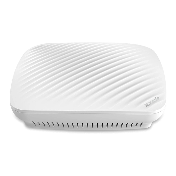
Getting to know your device 1.1 Overview Tenda i9 is a wireless access point specially designed for offices, bars, coffee shops and other indoor environments. Working at 2.4 GHz band, it provides a wireless transmission rate of as high as 300 Mbps. Featured with 2 built-in high gain omni-directional MIMO antennas, i9 provides powerful WiFi signal with strong wall penetration capacity and broad WiFi coverage. -
Page 9: Button And Port
1.2.2 Button and port Position of the label Reset button Power jack LAN port Button & Port Connection Description LAN port 10/100 Mbps auto negotiation port If the AP is powered using a DC adapter, connect this port to a switch. ... - Page 10 (1): Name of the AP. (2): Model of the AP. (3): Default IP address of the AP. You can use this IP address to log in to the web UI of the AP. (4): Default user name and password of the web UI of the AP. (5): MAC address of the AP.
-
Page 11: Application Scenarios
2.1 Small scale WiFi network deployment If you need to deploy a small scale WiFi network, you are recommended to use a wired router, a PoE switch, and several APs. 2.1.1 Deploying the AP with a Tenda router with the AP controller capacity Networking topology... -
Page 12: Deploying The Ap With A Router Without The Ap Controller Capacity
2.1.2 Deploying the AP with a router without the AP controller capacity If you deploy the AP with a router without the AP controller capacity, refer to the following networking topology. Networking topology Internet PoE Switch Router LAN port WAN port Uplink port AP …... -
Page 13: Large Scale Wifi Network Deployment
Connect the LAN port of the AP to the PoE port of the switch. − Setting up the AP Log in to the web UI of the Tenda AP controller, and set up the APs in batch. Refer to the user guide of the Tenda AP controller for details. -
Page 14: Login
Login 3.1 Logging in to the web UI of the AP Step 1 Connect the computer to the AP or the switch connected to the AP. Step 2 Set IP address of your local area connection to 192.168.0.X (X: 2 - 253) and Subnet mask to 255.255.255.0. - Page 15 If this page is not displayed, refer to in Appendix A "FAQ". --End You can now start configuring the AP.
-
Page 16: Logging Out Of The Web Ui Of The Ap
3.2 Logging out of the web UI of the AP After you log in to the web UI of the AP, the system logs you out if you perform no operation on the web UI within the interval. (The default interval is 5 minutes and can be changed.) Login Timeout When you close the web browser, the system logs you out as well. -
Page 17: Common Buttons On The Web Ui
Name Description ❶ Level-1 navigation tree The navigation bars display the function menu of the AP. When ❷ Level-2 navigation tree you select a function in navigation bar, the configuration of the function appears in the configuration area. ❸ Tab page area ❹... -
Page 18: Quick Setup
By default, the AP works in this mode. In this mode, the AP connects to the internet using an Ethernet cable and converts wired signals into wireless signals to provide wireless network coverage. See the following topology. Internet PoE Switch Router i9 in AP mode... - Page 19 In this mode, the AP is wirelessly bridged to an upstream device (such as a wireless router or AP) to extend the wireless network coverage of the upstream device. See the following topology. Internet Router PoE Switch i9 in APClient mode Upstream AP...
-
Page 20: Configuring Ap Mode
4.2 Configuring AP mode The Mixed WPA/WPA2-PSK security mode and AES encryption algorithm are used as an example to describe the configuration procedure. If you need to use another security mode, refer to Section 7.1 Basic settings. Configuration procedure: Step 1 Set Working Mode to AP. -
Page 21: Configuring Client+Ap Mode
4.3 Configuring Client+AP mode Configuration procedure: Before configuration, ensure that the upstream AP is connected to the internet successfully. Assume that the upstream AP has the basic information described in the following table. IP Address SSID Security Mode Security Key (Wireless Network Password) 192.168.0.254 Tenda_1 WPA2-PSK... - Page 22 --End Parameter description Parameter Description Working Mode It specifies the working mode of the AP, including AP Mode and Client+AP Mode. It specifies the SSID (wireless network name) of the upstream AP to be bridged. It is SSID populated automatically when you select the SSID of the upstream AP. It specifies the security mode of the wireless network to be bridged.
-
Page 23: Status
Status 5.1 System Status To view the system status and LAN status of the AP, choose Status > System Status. Parameter description Parameter Description It specifies the name of the AP. AP Name A unique Device Name helps quickly identify the AP. You can change the Device Name on the Network >... - Page 24 Parameter Description Hardware Version It specifies the hardware version number of the AP. It specifies the physical address of the LAN port of the AP. If you connect the AP to MAC Address other devices using Ethernet cables, the AP uses this MAC address to communicate with those devices.
-
Page 25: Wireless Status
5.2 Wireless Status To view the radio status and SSID status of the wireless network, choose Status > Wireless Status. Parameter description Parameter Description RF (On/Off) It specifies whether the wireless function of the AP is enabled. RF Status Network Mode It specifies the current network mode of the AP. -
Page 26: Traffic Statistics
5.3 Traffic Statistics To view the total transmitted traffic, total received traffic, total number of transmitted packets, and total number of received packets corresponding to each SSID of the AP, choose Status > Traffic Statistics. You can click Refresh to view the latest traffic statistics. -
Page 27: Wireless Clients
5.4 Wireless Clients To view the MAC address, IP address, connection uptime, transmit speed, and receive speed of each wireless client connected to the AP, choose Status > Wireless Clients. You can select an SSID from the drop-down list box in the upper-right corner to view information about the wireless clients connected to the AP using the SSID. -
Page 28: Network Settings
Network settings 6.1 LAN setup To view or configure the MAC address, device name, IP address obtaining mode, and other related information of the LAN port of the AP, choose Network > LAN Setup. Parameter description Parameter Description It specifies the MAC address of the LAN port of the AP. MAC Address The default primary SSID of the AP is Tenda_XXXXXX, where XXXXXX indicates the last 6 characters of this MAC address. -
Page 29: Ip Address Obtaining Mode - Static Ip Address
Parameter Description This IP address also functions as the management IP address of the AP. You can use this IP address to log in to the web UI of the AP to manage the AP. It specifies the subnet mask of the IP address of the AP if IP Address Type is set to Subnet Mask Static. -
Page 30: Ip Address Obtaining Mode - Dynamic Ip Address
Configuration procedure: Step 1 Set IP Address Type to Static. Step 2 Set IP Address. Step 3 Set Subnet Mask to the subnet mask of the IP address. Generally the subnet mask is 255.255.255.0. Step 4 Set Gateway to the IP address of the gateway of the AP. Step 5 Set Primary DNS Server to the IP address of the primary DNS server of the AP. - Page 31 --End...
-
Page 32: Dhcp Server
6.2 DHCP server 6.2.1 Overview The AP provides a DHCP server function to assign IP addresses to clients on the LAN. By default, the DHCP server function is disabled. If the new and original IP addresses of the LAN port belong to different network segment, the system changes the IP address pool of the DHCP server function of the AP so that the IP address pool and the new IP address of the LAN port belong to the same network segment. - Page 33 Parameter description Parameter Description It specifies whether to enable the DHCP server function. To enable it, select the check DHCP Server box. To disable it, deselect the check box. By default, it is disabled. It specifies the first IP address that can be assigned by the DHCP server to a client. The Start IP Address default value is 192.168.0.100.
-
Page 34: Dhcp Clients
6.2.3 DHCP clients If the AP functions as a DHCP server, you can view the DHCP client list to understand the details about the clients that obtain IP addresses from the DHCP server. The details include host names, IP addresses, MAC addresses, and lease times. To view information about the clients that obtain IP addresses from the DHCP server function of the AP, choose Network >... -
Page 35: Wireless Settings
Wireless Settings 7.1 Basic settings This module enables you to set SSID-related parameters of wireless networks of your AP. 7.1.1 Overview Broadcast SSID When the AP broadcasts an SSID, nearby wireless clients can detect the SSID. When this parameter is set to Disable, the AP does not broadcast the SSID and nearby wireless clients cannot detect the SSID. - Page 36 Max. Number of Clients This parameter specifies the maximum number of clients that can connect to the wireless network corresponding to an SSID. If the number is reached, the wireless network rejects new connection requests from clients. This limit helps balance load among APs. Security Mode ...
-
Page 37: Changing The Ssid Setup
WPA and WPA2 help significantly increase network security, making WPA and WPA2 the preferred security modes of wireless networks that require high security. 7.1.2 Changing the SSID setup To change the basic settings of an SSID, perform the following procedure: Step 1 Choose Wireless >... - Page 38 Parameter Description It specifies whether to broadcast the selected SSID. Enable: It indicates that the AP broadcasts the SSID and the SSID can be detected by clients. Disable: It indicates that the AP does not broadcast the SSID and the SSID cannot be ...
- Page 39 None It allows any wireless client to connect to a wireless network. This option is not recommended because it affects network security. Parameter description Parameter Description It specifies the encryption type for the WEP security mode of the AP. The options include Open, Shared, and 802.1x.
- Page 40 Parameter Description wireless network corresponding to the selected SSID only with the password specified by Key 2. It indicates that a key selected for the Open or Shared authentication type contains ASCII hexadecimal characters. 5 or 13 ASCII characters are allowed in the key. It indicates that a key selected for the Open or Shared authentication type contains hexadecimal characters.
- Page 41 Parameter Description TKIP: It indicates the Temporal Key Integrity Protocol. If TKIP is used, the maximum wireless throughput of the AP is limited to 54 Mbps. TKIP&AES: It indicates that both TKIP and AES encryption algorithms are supported. Wireless clients can connect to the wireless network corresponding to the selected SSID using TKIP or AES.
-
Page 42: Examples Of Configuring Ssid Setup
Parameter Description TKIP&AES: It indicates that both TKIP and AES encryption algorithms are supported. Wireless clients can connect to the wireless network corresponding to the selected SSID using TKIP or AES. It specifies the automatic update interval of a WPA key for data encryption. A shorter Key Update interval results in higher data security. - Page 43 Step 6 Click Save. --End Verification Wireless devices can connect to the FREE wireless network without a password.
- Page 44 Setting up a wireless network encrypted using WPA/WPA2-PSK Network requirement A company wireless network with a certain level of security must be set up through a simply procedure. In this case, WPA/WPA2 pre-shared key mode is recommended. PoE Switch Internet Router SSID: Hotspot Password: 87654321...
- Page 45 --End Verification Wireless devices can connect to the Hotspot wireless network with the password 87654321.
- Page 46 Setting up a wireless network encrypted using WPA or WPA2 Network requirement A highly secure wireless network is required and a RADIUS server is available. In this case, WPA or WPA2 mode is recommended. Internet PoE Switch Router RADIUS server IP address: 192.168.0.200 IP address: 192.168.0.254 SSID: hot_spot...
- Page 47 --End Configuring the RADIUS server Windows 2003 is used as an example to describe how to configure the RADIUS server. Step 1 Configure a RADIUS client. In the Computer Management dialog box, double-click Internet Authentication Service, right-click RADIUS Clients, and choose New RADIUS Client.
- Page 48 Enter a RADIUS client name (which can be the name of the AP) and the IP address of the AP, and click Next. IP address of your AP Enter 12345678 in the Shared secret and Confirm shared secret text boxes, and click Finish.
- Page 49 Step 2 Configure a remote access policy. Right-click Remote Access Policies and choose New Remote Access Policy. In the New Remote Access Policy Wizard dialog box that appears, click Next.
- Page 50 Enter a policy name and click Next. Select Ethernet and click Next.
- Page 51 Select Group and click Add. Enter 802.1x in the Enter the object names to select text box, click Check Names, and click OK.
- Page 52 Select Protected EAP (PEAP) and click Next. Click Finish. The remote access policy is created.
- Page 53 Right-click root and choose Properties. Select Grant remote access permission, select NAS-Port-Type matches "Ethernet" AND, and click Edit. Select Wireless – Other, click Add, and click OK.
- Page 54 Click Edit Profile, click the Authentication tab, configure settings as shown in the following figure, and click OK. When a message appears, click No. Step 3 Configure user information. Create a user and add the user to group 802.1x. --End...
- Page 55 Configure your wireless device Windows 7 is taken as an example to describe the procedure. Step 1 Choose Start > Control Panel, and click Network and Internet > Network and Sharing Center > Manage wireless networks. Step 2 Click Add.
- Page 56 Step 3 Click Manually create a network profile. Step 4 Enter wireless network information, select Connect even if the network is not broadcasting, and click Next. Same as the security mode of the WiFi network of the...
- Page 57 Step 5 Click Change connection settings. Step 6 Click the Security tab, select Microsoft: Protected EAP (PEAP), and click Settings.
- Page 58 Step 7 Deselect Validate server certificate and click Configure. Step 8 Deselect Automatically use my Windows logon name and password (and domain if any) and click OK.
- Page 59 Step 9 Click Advanced settings. Step 10 Select User or computer authentication and click OK.
- Page 60 Step 11 Click Close. Step 12 Click the network icon in the lower-right corner of the desktop and choose the wireless network of the AP such as hot_spot in this example.
- Page 61 Step 13 In the Windows Security dialog box that appears, enter the set on user name and password the RADIUS server and click OK. --End Verification Wireless devices can connect to the wireless network hot_spot.
-
Page 62: Rf Settings
7.2 RF Settings 7.2.1 Overview The RF module is used to set radio parameters of the AP. The following briefly describes the SSID isolation function. Isolate SSID This function isolates the wireless clients connected to different wireless networks of the AP. For example, if user 1 connects to the wireless network corresponding to SSID1, whereas user 2 connects to the wireless network corresponding to SSID2, the two users cannot communicate with each other after SSID isolation is implemented. - Page 63 --End Parameter description Parameter Description Enable RF It specifies whether to enable the RF function of the AP. It specifies the country or region where the AP is used. This parameter helps comply Country with channel regulations of the country or region. It specifies the wireless network mode of the AP.
- Page 64 Parameter Description MHz or 40 MHz according to the ambient environment. This option is effective only for 802.11b/g/n mixed network mode. It specifies an additional channel used to increase the channel bandwidth if the AP Extension Channel works in the 802.11b/g/n mixed network mode and the channel bandwidth option 40MHz or 20/40MHz is selected.
-
Page 65: Channel Scan
7.3 Channel Scan 7.3.1 Overview This function enables you to know wireless networks information nearby, including SSID, MAC address, channel and wireless signal strength. 7.3.2 Checking the usage of channels Step 1 Choose Wireless > Channel Scan. Step 2 Click Scan. --End Wait for a moment. -
Page 66: Wmm Setup
7.4 WMM Setup 7.4.1 Overview 802.11 networks offer wireless access services based on the Carrier Sense Multiple Access with Collision Avoidance (CSMA/CA) channel competition mechanism, which allows all wireless clients to fairly compete for channels. All the services implemented over wireless networks share the same channel competition parameters. -
Page 67: Changing The Wmm Settings
ACK Policies WMM specifies the Normal ACK and No ACK policies. According to the No ACK policy, no ACK packet is used during wireless packet transmission − to acknowledge packet reception. This policy is applicable to scenarios where interference is mild and can effectively improve transmission efficiency. - Page 68 Parameter description Parameter Description Enable: It is used to enable the WMM function. Disable: It is used to disable the WMM function. It specifies the WMM optimization modes supported by the AP: Optimized For Throughput(Concurrent Users <=10): If 10 or less clients are ...
-
Page 69: Advanced
Parameter Description EDCA Parameters For details, refer to section 7.5.1 Overview. 7.5 Advanced 7.5.1 Overview This module is used to set the RF performance optimization parameters of the AP. 7.5.2 Changing the advanced settings It is recommended that you change the settings only under the instruction of professional personnel, so as to prevent decreasing the wireless performance of the AP. - Page 70 Parameter Description It specifies the threshold of a fragment. The unit is byte. Fragmenting is a process that divides a frame into several fragments, which are transmitted and acknowledged separately. If the size of a frame exceeds this threshold, the frame is fragmented. Fragment Threshold In case of a high error rate, you can reduce the threshold to enable the AP to resend only the fragments that have not been sent successfully, so as to increase...
- Page 71 Parameter Description It specifies whether the current transmit power settings of the AP can be Lock Power changed. If it is selected, the settings cannot be changed. It specifies whether to use long preamble or short preamble. A preamble is a group of bits located at the beginning of a packet to enable a receiver of the packet to perform synchronization and prepare for receiving data.
-
Page 72: Access Control
7.6 Access Control 7.6.1 Overview It specifies, based on MAC address filter rules, the wireless devices that can or cannot access the wireless networks of the AP. Devices that have been controlled cannot connect to the corresponding wireless network. The AP supports the following MAC address filter rules: Disable: It indicates that access control is disabled. -
Page 73: Example Of Configuring Access Control
Parameter description Parameter Description SSID It specifies the SSID that requires wireless client access control. It specifies the mode for filtering MAC addresses. Disable: It indicates that access control is disabled. Allow: It indicates that only the wireless clients on the access control list can connect ... - Page 74 The following figure shows the configuration. Verification Only the specified wireless devices can connect to the Home wireless network.
-
Page 75: Qvlan Settings
7.7 QVLAN Settings 7.7.1 Overview The AP supports 802.1Q VLANs and is applicable in a network environment where 802.1Q VLANs have been defined. By default, the QVLAN function is disabled. 7.7.2 Configuring the QVLAN function Step 1 Choose Wireless > QVLAN Setup. Step 2 Change the parameters as required. -
Page 76: Example Of Configuring Qvlan Settings
If the QVLAN function is enabled, tagged data received by a port of the AP is forwarded to the other ports of the VLAN corresponding to the VID in the data, whereas untagged data received by a port of the AP is forwarded to the other ports of the VLAN corresponding to the PVID of the port that receives the data. - Page 77 Network Topology Internet Router Internal Server PoE Switch SSID for guests: internet VLAN 2 SSID for employees: oa VLAN 3 SSID for managers: VIP VLAN 4 Configuration procedure: Configure the AP Step 1 Log in to the web UI of the AP and choose Wireless > QVLAN Setup. Step 2 Select the Enable check box.
- Page 78 Configure the switch Create IEEE 802.1Q VLANs described in the following table on the switch. Port Connected To Accessible VLAN ID Port Type PVID 1, 2, 3, 4 Trunk LAN server 3, 4 Trunk Router 2, 4 Trunk Retain the default settings of other ports. For details, refer to the user guide for the switch. Configure the router and the internal server ...
-
Page 79: Snmp
SNMP 8.1 Overview The Simple Network Management Protocol (SNMP) is the most widely used network management protocol in TCP/IP networks. SNMP enables you to remotely manage all your network devices compliant with this protocol, such as monitoring the network status, changing network device settings, and receive network event alarms. -
Page 80: Snmp Protocol Version
8.1.3 SNMP protocol version The AP is compatible with SNMP V1 and SNMP V2C and adopts the community authentication mechanism. Community name is used to define the relationship between an SNMP agent and an SNMP manager. If the community name contained in an SNMP packet is rejected by a device, the packet is discarded. -
Page 81: Configuring The Snmp Function
8.2 Configuring the SNMP function Step 1 Choose SNMP and set SNMP Agent to Enable. Step 2 Set related SNMP parameters. Step 3 Click Save. --End Parameter description Parameter Description It specifies whether to enable the SNMP agent function of the AP. By default, it is disabled. -
Page 82: Example Of Configuring The Snmp Function
8.3 Example of configuring the SNMP function Networking requirement The AP connects to an NMS over an LAN. This IP address of the AP is 192.168.0.254/24 − and the IP address of the NMS is 192.168.0.212/24. The NMS use SNMP V1 or SNMP V2C to monitor and manage the AP. −... -
Page 83: Verification
--End Configure the NMS On an NMS that uses SNMP V1 or SNMP V2C, set the read community to Tom and read/write community to Tom 123. For details about how to configure the NMS, refer to the configuration guide for the NMS. Verification After the configuration, the NMS can connect to the SNMP agent of the AP and can query and set some parameters on the SNMP agent through the MIB. -
Page 84: Tools
Tools 9.1 Firmware Upgrade This function upgrades the firmware of the AP for more functions and higher stability. To prevent damaging the AP, verify that the new firmware version is applicable to the AP before upgrading the firmware and keep the power supply of the AP connected during an upgrade. Configuration procedure: Step 1 Download the package of a later firmware version for the AP from... -
Page 85: Time & Day
9.2 Time & Day This module enables you to set the interval of the AP. system time login timeout 9.2.1 System Time Ensure that the system time of the AP is correct, so that logs can be recorded correctly and the reboot schedule can be executed correctly. - Page 86 --End Manually setting the system time You can manually set the system time of the AP. If you choose this option, you need to set the system time each time after the AP reboots. Configuration procedure: Step 1 Choose Tools > Date & Time > System Time. Step 2 Deselect Sync with internet time servers.
-
Page 87: Login Timeout
9.2.2 Login Timeout If you log in to the web UI of the AP and perform no operation within the login timeout interval, the AP logs you out for network security. The default login timeout interval is 5 minutes. Procedure for setting the login timeout interval: Step 1 Choose Tools >... -
Page 88: Logs
9.3 Logs 9.3.1 View Logs The logs of the AP record various events that occur and the operations that users perform after the AP starts. In case of a system fault, you can refer to the logs during troubleshooting. To access the page, choose Tools > Logs and click View Logs. To ensure that the logs are recorded correctly, verify the system time of the AP. -
Page 89: Log Settings
9.3.2 Log settings To access the page, choose Tools > Logs and click Log Settings. On this page, you can set the number of logs to be displayed and configure log servers. Setting the number of logs to be displayed ... - Page 90 Configuring log server settings After a log server is specified, the AP sends its logs to the log server. You can view all the historical logs of the AP on the log server. To ensure that system logs can be sent to a log server, choose Network > LAN Setup and set the IP address, subnet mask, and gateway of the AP for communicating with the log server.
- Page 91 The following figure shows the configuration. Procedure for changing log server settings Step 1 To access the page, choose Tools > Logs and click Log Settings. Step 2 Click Change corresponding to the log server settings to be changed. Step 3 Change the parameter settings as required.
-
Page 92: Configuration
9.4 Configuration 9.4.1 Backup & Restore The backup function enables you to back up the current configuration of the AP to a local computer. The restoration function enables you to restore the AP to a previous configuration. If the AP enters the optimum condition after you greatly change the configuration of the AP, you are recommended to back up the new configuration, so that you can restore it after upgrading or resetting the AP. - Page 93 When the factory settings are restored, your configuration is lost. Therefore, you need to reconfigure the AP to connect to the internet. Restore the factory settings of the AP only when necessary. To prevent AP damages, ensure that the power supply of the AP is normal when the AP is reset. Restoring the Factory Settings Using Software Step 1 Choose Tools >...
-
Page 94: Account
9.5 Account To access page for changing user names and passwords, choose Tools > Account. On this page, you can change the login account information of the AP to prevent unauthorized login. Parameter description Parameter Description Administrator: An account of this type enables you to view and modify settings ... -
Page 95: Diagnostics Tool
9.6 Diagnostics Tool If the network connection fails, you can use the diagnostics tool included with the AP to locate the faulty node. Configuration procedure: The link to is used as an example. www.google.com Step 1 Choose Tools > Diagnostics. Step 2 Enter the IP address or domain name to be pinged in the Input text box. -
Page 97: Device Reboot
9.7 Device Reboot This module enables you to manually reboot the AP or configure the AP to automatically reboot. When the AP reboots, all connections are released. You are recommended to reboot the AP at an idle hour. 9.7.1 Manual Reboot If a setting does not take effect, you can try rebooting the AP to resolve the problem. - Page 98 --End Rebooting the AP at specified time Configuration procedure: Step 1 Choose Tools > Device Reboot and click the Automatic Reboot tab. Step 2 Select the Enable Auto Reboot check box. Step 3 Set Reboot Mode to At specified time. Step 4 Select the day or days when the AP reboots.
-
Page 99: Led Control
9.8 LED Control This function enables you to turn on/off the LED indicator of the AP. By default, the LED indicator is turned on. Procedure for turning off the LED indicator: Step 1 Choose Tools > LED Control. Step 2 Click Turn Off All Indicators. - Page 100 Appendixes A.1 FAQ I cannot access the web UI of the AP after entering 192.168.0.254. What should I do? Check the following items: Verify that the IP address of your computer is 192.168.0.X (X: 2~253). − Clear the cache of your web browser or replace the web browser, and try login again. −...
- Page 101 Account) if you use an AC to manage the AP. This improves network security. For more technical assistance, visit our website at or send your question http://www.tendacn.com . We will help you resolve your problem as soon as possible. support@tenda.cn...
- Page 102 A.2 Setting the IP Address of Your Computer Example: Windows 7 Step 1 Choose Start > Control Panel, click Network and Internet, click Network and Sharing Center, and click Change adapter settings. Step 2 Right-click Local Area Connection and choose Properties. Select Internet Protocol Version 4 (TCP/IPv4) and click Properties.
- Page 103 The Local Area Connection Properties dialog box appears. Step 4 Click OK. --End...
- Page 104 A.3 Default Parameter Settings The following table lists the factory settings of the AP. Parameter Default Value IP address 192.168.0.254 Login Administrator admin/admin User Name/Password User user/user Quick Setup Working Mode AP Mode IP Address Type Static IP Address (management IP address) 192.168.0.254 Subnet Mask 255.255.255.0...
- Page 105 Parameter Default Value Disable Max. Number of Clients Chinese SSID Encoding UTF-8 Security Mode None Wireless network Enable Network Mode 11b/g/n Channel Auto Channel Bandwidth 20/40 MHz Extension Channel Auto Lock Channel Enable Isolate SSID Disable APSD Disable Client Timeout Interval 5 minutes Beacon Interval 100 ms...
- Page 106 Parameter Default Value 2.4 GHz SSID VLAN ID 1000 SNMP Agent Disable Administrator Name Administrator AP Name Model + Hardware version number, such as i9V2.0 SNMP SNMP Location ShenZhen Parameters Read Community public Read/Write private Community Synchronize with Enable internet Time System Time (GMT+08:00) Beijing, Chongqing, Hong Kong, Time Zone...
Need help?
Do you have a question about the i9 and is the answer not in the manual?
Questions and answers