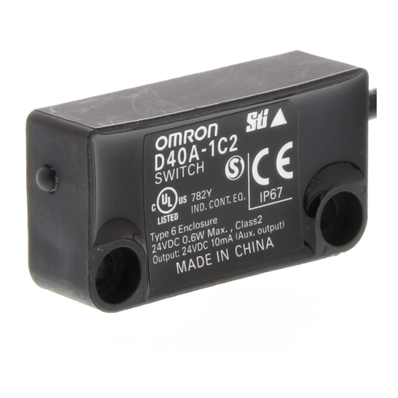
Omron G9SX Series Manual

Omron G9SX Series Manual

Compact non-contact door switch/ flexible safety unit stable operation increases line efficiency
Hide thumbs Also See for G9SX Series:

Advertisement

N E W
Compact Non-Contact Door Switch/
Flexible Safety Unit
D40A/G9SX-NS
Stable Operation Increases Line Efficiency

Advertisement

Table of Contents
loading

Summary of Contents for Omron G9SX Series

  • Page 1 N E W Compact Non-Contact Door Switch/ Flexible Safety Unit D40A/G9SX-NS Stable Operation Increases Line Efficiency...
  • Page 2 New Type of Non-Contact Door Switches for Worker Safety and Higher Productivity These new Non-Contact Door Switches provide more stability in detection than previously possible with non-contact door switches. Easy-to-see 2-Color Indicators Switch status is easy to see at a glance with these red/yellow LED indicators.
  • Page 3 ● Mount from Either Side Mount from whichever side provides the easiest wiring path to enable mounting to all types of doors. Mount from Either Side Swinging doors Swinging doors Sliding doors Sliding doors ● Connect Up to 30 Switches to a Single Controller Reduce costs by connecting up to 30 Switches to a single Controller.
  • Page 4 Two Types of Controller to Solve Productivity, Expandability, and Maintenance Issues The G9SX-NS and G9SX-NSA are designed specifically for use with the D40A, and with the G9SX-NSA you can also connect mechanical safety door switches. Among other features, these Controllers support logical AND connections that enable partial stops.
  • Page 5 ● Indicators That Make Maintenance Easier The indicators show the location and cause of wiring errors and any other errors that are detected. Auxiliary outputs for errors also contribute to reducing down Logical AND time. Input error Output error connection error ●...
  • Page 6 OMRON's unique logical AND connections enable easily constructing safety circuits that were troublesome with previous Controllers. The new Non-contact Door Switch Controllers embody the concepts for the G9SX Series, so you can also use the previous G9SX-series Controllers in the same system.
  • Page 7: Model Number Structure

    Compact Non-Contact Door Switch/Flexible Safety Unit D40A/G9SX-NS Electronic Detection Mechanism for Better Stability in Non-contact Door Switch Operation • Stable operation reduces Controller errors caused by unstable doors. • Connect up to 30 Non-contact Door Switches with LED indicators to one Controller. •...
  • Page 8: Ordering Information

    Ordering Information Non-Contact Door Switches (Switch/Actuator) Classification Appearance Auxiliary outputs Cable length Mode Standard models Semiconductor outputs D40A-1C2 (See note 2.) D40A-1C5 Note: 1. Must be used in combination with a G9SX-NS@ Non-contact Door Switch Controller. 2. PNP open-collector semiconductor output. Non-Contact Door Switch Controllers (Controllers for D40A) Safety outputs Auxiliary...
  • Page 9: Specifications

    Specifications ■ Ratings/Characteristics of Non-contact Door Switches Item Model D40A-1C@ Operating distance OFF → ON Operating 5 mm min. characteristics Operating distance ON → OFF 15 mm max. (See note 1.) Differential travel (max.) 20% of operating distance ± 20% of operating distance at 23 ° C, within temperature range of − 10 to 55 ° C Influence of temperature (max.) −...
  • Page 10: Power Input

    ■ Ratings of Non-contact Door Switch Controllers Power input Item Model G9SX-NS202-@ G9SX-NSA222-T03-@ G9SX-EX-@ Rated supply voltage 24 V DC − 15% to 10% of rated supply voltage Operating voltage range Rated power consumption (See note.) 3 W max. 4 W max. 2 W max.
  • Page 11 ■ Characteristics Item Model G9SX-NS202-@ G9SX-NSA222-T03-@ G9SX-EX-@ Over-voltage category II (Relay outputs 13 to 43 and 14 to (IEC/EN 60664-1) 44: III) Operating time (OFF to ON state) 100 ms max. (Logical AND 50 ms max. (Safety input: ON) 30 ms max. (See note 4.) connection input ON and Non- (See note 2.) (See note 1.)
  • Page 12 Logical AND Connection Item Model G9SX-NS202-@ G9SX-NSA222-T03-@ G9SX-EX-@ Number of Units connected per logical 4 Units max. AND output Total number of Units connected by logical 20 Units max. AND (See note 2.) Number of Units connected in series by 5 Units max.
  • Page 13 Response Time and Operating Time 1. G9SX-NS@ Max. response time Max. operating time Non-contact Door (excluding Expansion (excluding Expansion Switch input Units) (See note 1.) Units) (See note 2.) Logical AND input Non-contact Door Switch input 20 ms 100 ms Logical AND input 20 ms 100 ms...
  • Page 14: Engineering Data

    Engineering Data Detection Ranges (Typical Characteristics Data) −15 −10 −5 −6 −4 −2 Distance from the target mark on the switch Z (mm) Distance from the target mark on the switch X (mm) Sensing surface Sensing surface Target marks Target marks Note: 1.
  • Page 15 Connections ■ Internal Connection G9SX-NS202-@ (Non-contact Door Switch Controller) G9SX-NSA222-T03-@ (Non-contact Door Switch Controller) D1 D2 D3 D4 T31 T32 T33 T41 T42 T12 T21 T22 T31 T32 T33 Y1 D1 D2 D3 D4 T41 T42 (See (See note 2.) note Logical AND Power...
  • Page 16 Dimensions Note: All units are in millimeters unless otherwise indicated. Non-contact Door Switch (Switch/Actuator) D40A-1C2 Indicator Two, 4.2 dia. D40A-1C5 Sensing surface 7.2 dia. 7.2 dia. 7.2 dia. 7.2 dia. Sensing surface Two, 4.2 dia. Vinyl-insulated round cord, dia. 4, 5-conductor (conductor cross-sectional area: 0.2 mm ,Insulator diameter: 1.0 mm)
  • Page 17 Expansion Unit G9SX-EX401-@ Expansion Unit (OFF-delayed Model) G9SX-EX041-T-@ Terminal arrangement G9SX-EX401-@ G9SX-EX041-T-@ (Expansion Unit) (Expansion Unit with OFF Delay) (6) (See note 3.) 100 max. 14 24 14 24 23 max. 115 max. (6) (See note 3.) (22.5) (See note 1.) Note: 1.
  • Page 18 ■ Non-contact Door Switch and Non-contact Door Switch Controller Wiring Example: Wiring a Single Switch Example: Wiring Multiple Switches Connect Up to 30 Non-contact Door Switches D40A-1C @ Auxiliary output load (See note.) D1 D2 D3 D4 A2 G9SX-NS202-@ G9SX-NSA222-T03-@ Note: The auxiliary output load current must be 10 mA max.
  • Page 19 ■ Wiring of Inputs and Outputs G9SX-NS202-@ Signal name Terminal Description of operation Wiring name Power supply A1, A2 Connect the power source to the A1 and A2 terminals. Connect the power supply plus (24 VDC) to the A1 input terminal.
  • Page 20 G9SX-NSA222-T03-@ Signal name Terminal Description of operation Wiring name Power supply input A1, A2 Connect the power source to the A1 and A2 terminals. Connect the power supply plus (24 VDC) to the A1 terminal. Connect the power supply minus (GND) to the A2 terminal. Safety input 1 T11, T12 To set the safety outputs in the ON state, the high state...
  • Page 21: Operation

    Operation ■ Functions Connecting Expansion Units • The G9SX-EX and G9SX-EX-T Expansion Units can be connected to a G9SX-NSA222-T3-@ Non-contact Door Switch Controller to Logical AND Connection increase the number of safety outputs. (They cannot be connected to a G9SX-NS202-@.) A logical AND connection means that the G9SX outputs a safety •...
  • Page 22: Setting Procedure

    Setting Procedure 3. Setting Logical AND Connection (G9SX-NS202-@/ NSA222-T03-@) 1. Cross Fault Detection (G9SX-NSA222-T03-@) When connecting two or more Non-contact Door Switch Controllers by logical AND connection, set the logical AND Set the cross fault detection mode for safety inputs by shorting Y1 connection preset switch on the Controller that is on the input side to 24 V or leaving it open.
  • Page 23: Led Indicators

    LED Indicators Marking Color Name G9SX-NS202 G9SX- G9SX-EX G9SX-EX-T Function Refer- NSA222 ence ❍ ❍ ❍ ❍ Green Power supply Lights while power is supplied. indicator ❍ Orange Safety input #1 Lights while a high signal is input to (See T12.
  • Page 24: Fault Detection

    Fault Detection When the Non-contact Door Switch Controller detects a fault, the ERR indicator and/or other indicators light up or flash to inform the user about the fault. Check and take necessary measures referring to the following table, and then re-supply power to the Non-contact Door Switch Controller. (G9SX-NS202-@/NSA222-T03-@) Other Fault...
  • Page 25 Other Fault Expected causes of the fault Check points and measures to take indicator indicator Fault involved with logical 1. Error in the wiring of the logical AND 1. Check the wiring to T41 and T42. connection input AND connection input Note: 1.
  • Page 26: Application Examples

    Application Examples G9SX-NSA222-T03-@ (24 VDC) (1-channel Emergency Stop Switch Input + Non-contact Door Switch/Manual Reset) Feedback Loop +24 V Motor controller +24 V T11 T12 T21 T22 T31 T32 T33 Y1 D1 D2 D3 D4 T41 T42 Timing chart G9SX-NSA222-T03 Emergency stop switch operation +24 V...
  • Page 27 G9SX-BC202 (24 VDC) (2-channel Emergency Stop Switch Input/Manual Reset) + G9SX-NS202-@ (24 VDC) (Non-contact Door Switch Input/Auto Reset) Feedback Loop +24 V A1 T11 T11 T12 T21 T22 T31 T32 T33 Y1 G9SX-BC202 +24 V Control circuit S1: Emergency Stop Switch S2: Reset Switch KM1, KM2: Contactor M1: 3-phase motor...
  • Page 28 Precautions For details, refer to Precautions for All Relays and Precautions for All Relays with Forcibly Guided Contacts in the Safety Components Group Catalog (Cat. No. Y106). ■ Precautions for Safe Use !CAUTION 1. Disconnect the G9SX-NS from the power supply when wiring the Serious injury may possibly occur due to breakdown of D40A.
  • Page 29 2. The D40A must be used with a designated actuator and G9SX- 19.OMRON is not responsible for conformity with any safety NS@ Controller. standards covering the customer's entire system. 3. Handle with Care.
  • Page 30 11.Install the actuator and switch at an appropriate distance so that 18.The following space must be provided around the G9SX-NS@ to they do not create a gap that provides access to the hazard. enable applying the rated current to the outputs of the G9SX- NS@, to ensure sufficient ventilation, and to enable wiring: 1.
  • Page 31 EN 954-1. The settings are determined by circuit logical AND connection outputs of the G9SX-@. examples provided by OMRON, however, and may not be applicable depending on the operating conditions. Safety categories are 3. When configuring the safety system, be sure to consider that determined for the safety control system as a whole.
  • Page 32 Warranty and Limitations of Liability WARRANTY OMRON's exclusive warranty is that the products are free from defects in materials and workmanship for a period of one year (or other period if specified) from date of sale by OMRON. OMRON MAKES NO WARRANTY OR REPRESENTATION, EXPRESS OR IMPLIED, REGARDING NON-INFRINGEMENT, MERCHANTABILITY, OR FITNESS FOR PARTICULAR PURPOSE OF THE PRODUCTS.

Table of Contents