Advertisement
Floatless Level Switch (Basic Type)
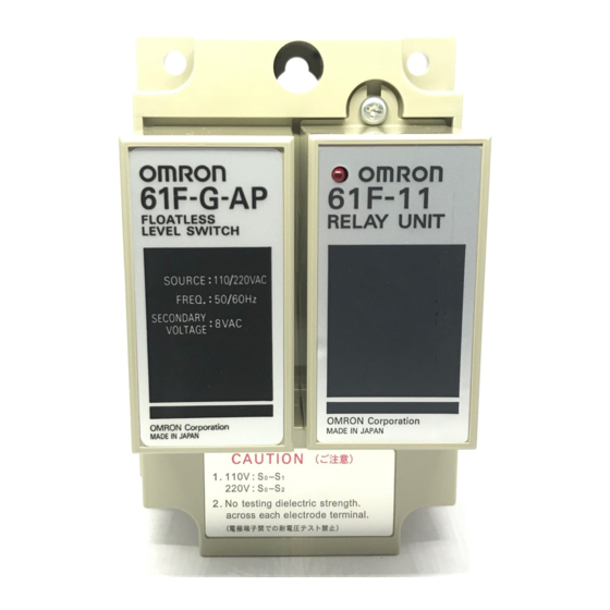
61F-G@
Basic Building-block Controllers That Mount
Directly to Panels for Easier Maintenance
• Easy maintenance with building-block Relay Units.
• Easy identification of operating status with LED operation
indicator.
• Lineup includes models for tropical regions and for high
temperatures. Achieve stable detection even in high-
temperature environments.
Refer to Safety Precautions for Floatless Level
Controllers.
Model Number Structure
61F-@@
1 2
1. Control Application
G: Automatic water supply and drainage
G1: Automatic water supply with idling prevention or water
shortage alarm
G2: Automatic water supply and drainage with abnormal
water increase alarm
G3: Automatic water supply and drainage with full tank and
water shortage alarm
G4: Automatic water supply with water level indicator for
water supply tank and water receiving tank and
prevention of idling due to water shortage
I:
Liquid level indication and alarm (no two-wire models)
2. Type
Blank: General-purpose
L 2KM: Long-distance (for 2 km)
L 4KM: Long-distance (for 4 km)
H:
High-sensitivity
D:
Low-sensitivity
R:
Two-wire
T:
High-temperature
CSM_61F-G__DS_E_4_2
Position of
LED indicator
1
Advertisement
Table of Contents

Related Manuals for Omron 61F-G


Summary of Contents for Omron 61F-G
- Page 1 Floatless Level Switch (Basic Type) 61F-G@ CSM_61F-G__DS_E_4_2 Basic Building-block Controllers That Mount Directly to Panels for Easier Maintenance • Easy maintenance with building-block Relay Units. • Easy identification of operating status with LED operation indicator. • Lineup includes models for tropical regions and for high temperatures.
-
Page 2: Ordering Information
Example: 61F-G [110/220 VAC] Desired supply voltage 2. If you order with a standard model number, the corresponding Relay Units are also delivered as part of a set. If you order the 61F-G, one 61F-11 Relay Unit is included in the set. - Page 3 8 VAC InterElectrode current Approx. 1 mA AC max. Power consumption 61F-G@: 3.5 VA max.; G1F-G1@, G1F-G2@, or G1F-I@: 5.5 VA max.; G1F-G3@: 7.5 VA max.; G1F-G4@: 14.5 VA max. InterElectrode operate 0 to approx. 4 kΩ 0 to approx. 5 kΩ 0 to approx.
- Page 4 61F-G@ Internal Circuit Diagrams The schematic diagrams shown below typify the internal connections of the various 61F models. The designations Ta, Tb, and Tc (sometimes referred to collectively as “U”) may occur more than once in a product, however, the “a” terminal is always an NO contact, a “b” terminal is an NC contact, and the “c”...
- Page 5 61F-G@ Note: The 61F11H relay deenergizes when there is water present across the Electrodes, whereas the 61F relay energizes when there is water present across the Electrodes. Also, the terminal connections of those Controllers provided with LED indicators differ from those which have no indicators.
- Page 6 61F-G@ ■ Connections Automatic Water Supply and Basic Type Drainage Control 61F-G Dimensions: page 14 Automatic Water Supply Control Automatic Drainage Control Connections Connections 61F-G 61F-G 220-VAC power supply 220-VAC Power supply 61F-11 61F-11 24 V 24 V Relay Unit...
- Page 7 61F-G@ Automatic Water Supply Control with Basic Type Pump Idling Prevention and Automatic 61F-G1 Water Supply Control with Abnormal Water Shortage Alarm Dimensions: page 14 Automatic Water Supply Control with Pump Idling Prevention Automatic Water Supply Control with Abnormal Water Shortage Alarm...
- Page 8 61F-G@ Automatic Drainage Control and Basic Type Water Supply with Abnormal 61F-G2 Water Increase Alarm Dimensions: page 14 Automatic Water Supply with Overfull Tank Alarm Automatic Drainage Control with Overfull Tank Alarm Connections Connections 61F-G2 61F-G2 220 VAC power supply...
- Page 9 61F-G@ Automatic Water Supply and Drainage Basic Type Control with Abnormal Water Increase and 61F-G3 Water Shortage Alarms Dimensions: page 14 Automatic Water Supply with Abnormal Water Increase and Water Shortage Alarms Automatic Drainage Control with Abnormal Water Increase and Water Shortage Alarms...
- Page 10 61F-G@ Automatic Water Supply Control with Water Basic Type Source Level Indication, Prevention of 61F-G4 Pump Idling Due to Water Shortage, and Indication of Water Level in Tank Dimensions: page 14 Automatic Water Supply Control with Water Source Level Indication, Prevention of Pump Idling Due to Water Shortage, and Indication of Water Level in Tank Connections •...
- Page 11 When supplying power from N-phase to the Controller in three-phase four-line circuit, refer to the following diagrams. Line voltage (R-S, S-T, or R-T): 380 or 415 VAC Phase voltage (N-R, N-S, or N-T): 220 or 240 VAC 61F-G@, 220 or 240 VAC Water Supply Power source 380 or 415 VAC...
- Page 12 61F-G@ Liquid Level Indication and Alarm Basic Type 61F-I Dimensions: page 14 Liquid Level Indication and Alarm Connections • Power Supply Connections 110 VAC: Connect S and S 220 VAC: Connect S and S 220-VAC power supply 61F-I 61F-11 24 V...
- Page 13 61F-G@ ■ Two-Wire Connections Automatic Water Supply and Basic Type Drainage Control 61F-GR Automatic Water Supply Control Automatic Drainage Control Connections Connections 220-VAC power supply 220-VAC power supply 61F-GR 61F-GR 61F-11R 61F-11R MCCB MCCB 24 V 24 V Relay Unit...
- Page 14 61F-G@ Dimensions Note: All units are in millimeters unless otherwise indicated. ■ Standard Models 61F-G Mounting Holes M3 screw Four, 6-dia mounting holes Four, 6-dia holes 61F-G1 Mounting Holes 61F-G2 M3 screw 61F-I Four, 6-dia mounting holes Four, 6-dia holes...
- Page 15 (a) Exclusive Warranty. Omron’s exclusive warranty is that the Products will be free from defects in materials and workmanship for a period of twelve months from the date of sale by Omron (or such other period expressed in writing by Omron). Omron disclaims all other warranties, express or implied.
Need help?
Do you have a question about the 61F-G and is the answer not in the manual?
Questions and answers