Table of Contents
Advertisement
Available languages
Available languages
Quick Links
Original instructions
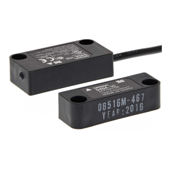
Type D40A
Compact Non-Contact Door Switch
The D40A non-contact door switch provides a
safety-related interruption at a specified proximity
position of its actuator through a safety controller.
INSTRUCTION MANUAL
English
Thank you for purchasing D40A Compact Non-contact
Door Switch. Please read and understand this manual
before using the products. Keep this manual ready to
use whenever needed. Only qualified person trained
in professional electrical technique should handle
D40A. Please consult your OMRON representative if
you have any questions or comments. Make sure that
information written in this document are delivered to
the final user of the product.
2139497-6E
© OMRON Corporation 2010-2022 All Rights Reserved.
Instructions in the EU languages and a signed EU Declaration
of Conformity are available on our website at
http://www.industrial.omron.eu/safety.
Declaration of Conformity
OMRON declares that D40A is in conformity with the requirements
of the following EU Directives and UK Legislation:
EU: Machinery Directive 2006/42/EC, EMC Directive 2014/30/EU,
RoHS Directive 2011/65/EU
UK: 2008 No. 1597 Machinery (Safety), 2016 No. 1091 EMC,
2012 No. 3032 RoHS
Safety Standards
D40A is designed and manufactured in accordance with
the following standards:
EN ISO13849-1:2015
Cat. 3 PL d
(with G9SX-NS)
IEC/EN61508 SIL3
,
(with G9SX-NS)
IEC/EN60947-5-3 PDDB
,
(with G9SX-NS)
IEC/EN61000-6-4, ISO14119 (Low level coded),
UL508, CAN/CSA C22.2 No.14
Safety Precautions
Meanings of Signal Words
The following signal words are used in this manual.
Indicates a potentially hazardous
situation which, if not avoided, will
result in minor or moderate injury, or
WARNING
may result in serious injury or death.
Additionally there may be significant
property damage.
Alert Statements
WARNING
Machine may start operating and may result serious
injury or death.
Do not put the actuator close to the switch when the
door is opened.
Also make sure to install D40A to minimize defeat
possibilities. For required measures, refer to ISO14119
and other relevant standards and regulations.
Precautions for Safe Use
(1) Disconnect G9SX-NS from power supply when wiring D40A.
Devices connected to G9SX-NS may operate unexpectedly.
(2) Do not operate the D40A with flammable or explosive gas.
(3) Incorrect wiring may lead to loss of safety function. Wire
conductors correctly and verify the operation of D40A before
using the system in which D40A is incorporated.
(4) Auxiliary monitoring output is NOT safety output. Do not use
auxiliary monitoring output as any safety output. Such incorrect
use causes loss of safety function of D40A and its relevant system.
(5) After installation of D40A, qualified personnel should confirm the
i n s t a l l a t i o n , a n d s h o u l d c o n d u c t t e s t o p e r a t i o n s a n d
maintenance.The qualified personnel should be qualified and
authorized to secure the safety on each phases of design,
installation, running, maintenance and disposal of system.
(6) A person in charge, who is familiar to the machine in which D40A
is to be installed, should conduct and verify the installation.
(7) Be sure to inspect D40A daily and every 6 months. Otherwise,
serious injury may possibly occur due to the system malfunction.
(8) Do not dismantle, repair, or modify D40A. Doing so may lead to
loss of its safety functions.
(9) Use only appropriate components or devices complying with relevant
safety standards corresponding to the required level of safety
category. Conformity to requirements of safety category is determined
as an entire system. It is recommended to consult a certification body
regarding assessment of conformity to the required safety level.
Precautions for Correct Use
(1) D40A must be used with designated actuator (D40A-1C or -A1)
and designated controller type G9SX-NS. Before using the D40A
with any other OMRON Safety Controller, check applicability in the
Instruction Manual for the other Controller.
(2) Handle with care
Do not drop D40A to the ground or expose to excessive vibration
or mechanical shocks. D40A may be damaged and may not
function properly.
(3) Conditions of storage and usage
Do not store or use the D40A under the following conditions.
D40A may be damaged and may not function properly.
1) In direct sunlight
2) At ambient temperatures out of the range of –10 to 55°C
3) At relative humidity out of the range of 25% to 85% or under
such temperature change that causes condensation.
4) In corrosive or combustible gases
5) With vibration or mechanical shocks out of the rated values.
6) Under splashing of oil or chemicals
7) In the atmosphere containing dust, saline or metal powder.
8) Where steel scrap or metal powder may fall directly to D40A.
(4) Use cables with length less than 100m totally to connect multiple
D40A switches.
The supply voltage to D40A may decrease by the
voltage drop depending on the cable or the wiring configuration.
Check the power-supply vloltage is in the rated range.
Total wiring length 100m max.
D1 D2 D3 D4
G9SX-NS202
G9SX-NSA222
(5) Disconnect G9SX-NS from power supply when replacing D40A.
Devices connected to G9SX-NS may operate unexpectedly.
(6) Adhesion of solvent such as alcohol, thinner, trichloroethane or
gasoline on the product should be avoided. Such solvents make
the marking on D40A illegible and cause deterioration of parts.
(7) Do not use D40A in the magnetic field of 1.5mT or more. D40A
may not function properly.
(8) Do not use D40A in the water or continuous water exposure
environment, otherwise water may leak into D40A. (An
enclosure of IP67 rating, which D40A is rated, protects against
temporary immersion in water.)
(9) Do not use the switch or actuator as a stopper. Protect the switch
and the actuator by setting up the stopper. Separate the switch
and the actuator to a distance of 1mm or more.
(10) Install D40A actuator and switch in an appropriate distance so
that it does not create a gap accessible to the hazard.
(11) Where two or more switches mounted adjacent, they should be
no closer than 25mm.
25mm Min.
(12) Check that the machine is stopped whenever the interlocked
guard door is open.
(13) Do not mount the switch and actuator on magnetic materials,
otherwise it may affect the operating distance.
Refer to the chart below for the estimated influence.
Distance from
Operating distance
magnetic materials
0 to 5mm
Approximately 90% of the original value
5mm Min.
No influence
(14) Tighten each screw with specified torque by using M4 screw
,
and washer for the installation of the switch and actuator. After
installation and commissioning, the actuator and switch fixing
screws should be coated with tamper proof varnish or similar
compound.Using anaerobic locking compounds can have a
detrimental effect on the plastic switch case if the compounds
contact with the switch case.
Switch
(15) Wiring
1.Use the following to wire to G9SX-NS
2
-Solid wire: 0.2 to 2.5mm
AWG24 to AWG12
-Stranded wire: 0.2 to 2.5mm
2
AWG22 to AWG12
2.When auxiliary output is not used, cut off the wiring and
protect by taping so that it does not contact other terminals.
3.When you use an additional cable of 20m or longer,
use a multiconductor cable to group the white, black,
brown, and blue lines together.
(16) Handle cables with care:
1) For bending cables, it is recommended to bend them with a
radius of bend no less than six times the cable outer diameter.
2) Do not apply a tensile strength of 50N or greater to the cables.
(17) In a residential environment, this product may cause radio
interference, in which case the user may be required to
take adequate measures.
(18) If there is any machine that has a large surge current(e.g.,
a motor) near D40A, connect a surge absorber to D40A
between the blue and the other lines (white, black, brown,
and yellow), respectively.
Suggested surge absorber's specification is as follows:
-Peak pulse power: 600W (10/1000μs) or more
(Per IEC61000-4-5(surge immunity))
-Breakdown voltage: 27-33V
1
Detection Ranges (Engineering data)
5mm (point A)
15mm (point B)
ON
OFF
Y-direction movement
Sensing
X
surface
Y
18
18
Target marks
OFF range
16
16
Maximum
14
14
B
operating distance
(ON to OFF)
12
12
Engineering Data
10
(ON to OFF)
10
Engineering Data
8
8
(OFF to ON)
6
Minimum
6
operating distance
4
A
(OFF to ON)
4
2
ON range
2
0
0
6
4
2
0
2
4
6
15 10
Distance from the target mark on the switch X (mm)
Distance from the target mark on the switch Z (mm)
Note1. The operating distance is the distance between the switch and
actuator sensing surfaces.
Note2. The graph indicates shifting to X or Z direction from following
condition that the switch and actuator target marks are on the same
axis and the sensing surfaces are exactly parallel condition.
Dashed lines indate reference value for maximum and minimun
oprating distance at abient temperature +23°C. The solid line indicates
reference values of the maximum and minimum operating distances.
Switch and actuator operation
2
Switch and Actuator Mounting Directions
Switch
Switch
Actuator
Switch and Actuator Operating Directions
LED Display
LED color Status
Sensor does NOT detect actuator
RED
Sensor detect actuator
YELLOW
3
Internal connection
brown / 1
blue / 3
4
white / 2
black / 4
yellow / 5
1
4
Ratings and Specifications
Ratings
Item
Rated power consumption
Auxiliary output
Specifications and Performance
Item
OFF
ON
Assured
ON
OFF
operating
Differential travel
and
release
Temperature influence
distance
Repeat
accuracy (max.)
Switching frequency
Ambient temperature
Ambient humidity
Insulation resistance
(Between all conductive parts and switch case)
Dielectric strength
(Between all conductive parts and switch case)
Rated impulse
withstand voltage
Vibration resistance
Mechanical shock resistance
Pollution degree
Electromagnetic compatibility As per IEC/EN 60947-5-3
Degree of protection
Material
Mounting method
Terminal tightening torque
Weight (D40A-1C5)
Relaiability data
Actuator
(ISO 13849-1)
Note1. Power consumption of loads is not included.
Note2. Operating distance means the distance of sensing surfases
between switch and actuator.
5
Connection Example
Multiple switch connection
Maximum 30 switches can be connected in series.
D1 D2 D3 D4
G9SX-NS202
G9SX-NSA222
Wiring
Signal Name
Non-contact door
switch power input
Non-contact door switch
Unstable
signal input
range
Non-contact door switch output
Sensing
surface
Auxiliary monitoring output
Z
Y
(PNP open corrector output)
Target marks
OFF range
Maximum
B
operating distance
(ON to OFF)
Engineering Data
(ON to OFF)
Engineering Data
LED indicator Note1
(OFF to ON)
Minimum
D40A
G9SX-NS
operating distance
A
(OFF to ON)
ON range
Failures involving the wiring of power supply input
5
0
5
10
15
Light off
NS Light off
Failures of the parts of the circuits of D40A
Installation on magnetic substance
Installation in the vicinity of magnetic source
Red
NS Light off
Light on
Failures of the parts of the circuits of D40A
Failures involving the wiring of D40A input
Failures involving the wiring of D40A outputs
NS Light off
Yellow
or NS Blink
Light on
Failures of the parts of the circuits of D40A
Note 1. When actuator is approximated to the switch.
Performance Level / Safety Category
The D40A together with G9SX-NS□ can construct the condition
conforming to PL=d and Category 3 required by EN ISO 13849-1
European standard.
Actuator
Refer to the following link for the Safety-related characteristic data:
http://www.fa.omron.co.jp/safety_6en/
This does NOT mean that D40A and G9SX-NS can always be used
for required category under all the similar conditions and situations.
UL does not provide UL certification for any functional safety rating
or aspects of the D40A device.
Conformity to the categories must be assessed as a whole system.
When using D40A and G9SX-NS for safety categories, make sure
the conformity of the whole system.
Suitability for Use
Omron Companies shall not be responsible for conformity with any standards,
codes or regulations which apply to the combination of the Product in the
Buyer's application or use of the Product. At Buyer's request, Omron will
provide applicable third party certification documents identifying ratings and
limitations of use which apply to the Product. This information by itself is not
sufficient for a complete determination of the suitability of the Product in
combination with the end product, machine, system, or other application or
use. Buyer shall be solely responsible for determining appropriateness of the
particular Product with respect to Buyer's application, product or system.
Buyer shall take application responsibility in all cases.
3
NEVER USE THE PRODUCT FOR AN APPLICATION INVOLVING SERIOUS
RISK TO LIFE OR PROPERTY OR IN LARGE QUANTITIES WITHOUT
5
ENSURING THAT THE SYSTEM AS A WHOLE HAS BEEN DESIGNED TO
ADDRESS THE RISKS, AND THAT THE OMRON PRODUCT(S) IS
PROPERLY RATED AND INSTALLED FOR THE INTENDED USE WITHIN
2
THE OVERALL EQUIPMENT OR SYSTEM.
6
Dimensions
Switch
D40A-1C
0.6W Max. (See Note1)
Load: 24VDC 10mA
(PNP open-collector output)
Indicator
D40A-1C
5mm min.
(See Note2)
15mm max.
(See Note2)
See " 1 Detection ranges"
See " 1 Detection ranges"
Target mark
±10% of operating distance at 23°C
1Hz with G9SX-NS□
-10 to +55 °C
(No freezing or condensation)
25 to 85%RH
Sensing surface
50Mohm Min.
(by 500VDC megger)
D40A-1C015-F
1000VAC for 1min
1kV
Frequency: 10 to 55 to 10Hz,
Amplitude: 0.75mm half amplitude
300m/s
Min.
2
Sensing surface
3
IP67
Actuator
Molded PBT
M4 screws
Two. 4.2 dia.
1N•m
Switch: approx. 145 g
Actuator: approx. 20 g
MTTFd = 100 year, DC = 60%
*This data does not include the
values of a safety controller.
Single switch connection
G9SX-NS202
G9SX-NSA222
Note 1. Maximum auxiliary output current is 10mA.
Cable color
Description of operation
Pim number
+
brown
1
Power supply for D40A.
Connect to D3 terninal and D4 terminal on G9SX-NS.
-
blue
3
Input designated signal from G9SX-NS.
white
2
To set non-contact door switch output in ON state, non-contact door
switch input must be in ON state.
Output status depends on actuator status and non-contact door switch
black
4
input state.
yellow
5
Output when sensor detect actuator.
Troubleshooting
Expected causes of the faults
Checking points and measures to take
Check that the brown and the blue cable are correctly connected
with G9SX-NS's D3 terminal and terminal D4 respectively.
Replace with a new D40A
Install the switch and actuator on a non-magnetic material.
Install D40A separate from a strong magnetic source.
Replace with a new D40A
Check that the white cable is correctly connected with G9SX-NS's D1 terminal.
Check that the black cable is correctly connected with G9SX-NS's D2 terminal.
Replace with a new D40A
•
Daily inspection:
1.Check every guard door to see that machine stops
when guard door is opened.
• 6-month inspection:
1. Isolate all power.
2. Check the switch and actuator for proper alignment.
3. Check terminals for proper connections.
4. Check wiring for signs of damage.
5. Before resuming normal machine operation,
check every guard door to see that machine stops
when the guard door is opened.
OMRON Corporation
Shiokoji Horikawa, Shimogyo-ku, Kyoto, 600-8530 JAPAN
Regional Headquarters
OMRON EUROPE B.V. (Importer in EU)
Wegalaan 67-69, 2132 JD Hoofddorp
The Netherlands
Tel: (31)2356-81-300/Fax: (31)2356-81-388
OMRON ELECTRONICS LLC
2895 Greenspoint Parkway, Suite 200
Hoffman Estates, IL 60169 U.S.A.
Tel: (1) 847-843-7900/Fax: (1) 847-843-7787
OMRON ASIA PACIFIC PTE. LTD.
438B Alexandra Road, #08-01/02
Alexandra Technopark,
Singapore 119968
Tel: (65) 6835-3011/Fax: (65) 6835-2711
OMRON (CHINA) CO., LTD.
Room 2211, Bank of China Tower,
200 Yin Cheng Zhong Road,
PuDong New Area, Shanghai, 200120, China
Tel: (86) 21-5037-2222/Fax: (86) 21-5037-2200
Cable diameter : 4
Cross section
7.2 dia.
7.2 dia.
of conductor:
0.2mm
(AWG24)
2
Two. 4.2 dia.
13
38
(1.5)
48
(2)
15 dia.
M12
(46)
(150)
Target mark
38
48
7.2 dia.
7.2 dia.
Sensing surface
D40A-1C
aux. output load
*Note 1
D1 D2 D3 D4
A2
Inspection & Maintenance
(Manufacturer)
Contact: www.ia.omron.com
Advertisement
Table of Contents

Related Manuals for Omron D40A


Summary of Contents for Omron D40A
- Page 1 Output status depends on actuator status and non-contact door switch Y-direction movement Sensing Sensing black (6) A person in charge, who is familiar to the machine in which D40A surface input state. surface is to be installed, should conduct and verify the installation.
-
Page 2: Problembehebung
Betriebsabstand bei einer Umgebungstemperatur von Montieren Sie den D40A außerhalb der Reichweite Lassen Sie die D40A nicht zu Boden fallen und setzen Sie sie auch keiner +23 °C. Die durchgehende Linie zeigt die Referenzwerte für die Montage in der Nähe einer Magnetquelle... -
Page 3: Manuel D'utilisation
à une température ambiante de +23 °C. La ligne éteint Ne faites pas tomber le D40A sur le sol et ne l'exposez pas à des Pannes au niveau des pièces des circuits du D40A Remplacez par un D40A neuf. -
Page 4: Manual Del Usuario
(2) Manipular el producto No tire al suelo el D40A ni lo exponga a una vibración excesiva o a choques Averías en las piezas de los circuitos del D40A Sustitúyalo por un D40A nuevo. mecánicos.El D40A podrá sufrir daños y no funcionar correctamente. -
Page 5: Manuale Per L'utente
8) Dove c'è il rischio che scarti o polvere metallica si depositino sul D40A. (4) Utilizzare cavi della lunghezza totale inferiore a 100 m per collegare D40A può offrire livelli di performance e classi fino a PL=d e Classe 3 richiesti dalla • Verifiche giornaliere: interruttori D40A più. - Page 6 Licht uit NS licht uit Fouten van de onderdelen van de circuits van de D40A Vervang door een nieuwe D40A Opmerking 2. De grafiek geeft de verschuiving in X- of Z-richting weer onder de gebruikt. Controleer voordat de D40A met een andere...
- Page 7 (6) En person, der har ansvaret, og som er bekendt med maskinen, dørkontakt for berøringsfri dørkontakt. hvori D40A skal installeres, skal foretage og verificere installationen. Ekstra overvågningsudgang (7) Sørg for at inspicere D40A dagligt og hver 6. måned. I modsat fald kan Udsendes, når føler registrerer aktuator. Målmærker Målmærker FRA-område FRA-område...
- Page 8 G9SX-NS202 Muutoin G9SX-NS:ään kytketyt laitteet saattavat toimia odottamatta. Syöksyvirran vaimentimen tekniset suositusarvot ovat seuraavat: (2) Älä käytä D40A:ta ympäristössä, jossa on syttyviä tai räjähtäviä kaasuja. G9SX-NSA222 – Pulssin huipputeho: 600 W (10/1000 μs) tai enemmän (3) Virheellinen johdotus voi aiheuttaa turvatoiminnon estymisen.
- Page 9 (7) Se till att inspektera D40A dagligen och var 6:e månad. I annat Reservmonitorutgång Mata ut när sensorn känner av manöverdonet. fall kan allvarlig skada inträffa p.g.a. funktionsfel i systemet.
-
Page 10: Instrukcja Obsługi
Maks. 0,6 W (patrz Uwaga 1) 0,2 mm (AWG24) (8) Czujnika D40A nie należy używać w wodzie lub w środowisku stale narażonym Obciążenie: 24 V DC 10 mA Kompaktowy bezstykowy czujnik otwarcia drzwi na oddziaływanie wilgoci; w przeciwnym wypadku może dojść do wniknięcia Wyjście pomocnicze... -
Page 11: Инструкция По Эксплуатации
Максимальное (выход с открытым коллектором PNP) Максимальное рабочее расстояние рабочее расстояние (7) Обязательно проверяйте D40A ежедневно и через каждые 6 месяцев. В (ВКЛ. → ВЫКЛ.) (ВКЛ. → ВЫКЛ.) противном случае возможны тяжелые травмы из-за неполадок в системе. Технические данные Технические данные... -
Page 12: Manual De Instruções
(18) Se alguma máquina próxima do D40A apresentar uma grande corrente de G9SX-NS202 ligação elétrica do D40A. Os dispositivos ligados ao G9SX-NS surto (p. ex., um motor), ligue um absorvedor de surto ao D40A entre a linha poderão funcionar de forma inesperada. G9SX-NSA222 azul e as restantes (branca, preta, castanha e amarela), respetivamente. -
Page 13: Kullanim Kilavuzu
önlemleri alması gerekebilir. Güvenli Kullanım için Önlemler G9SX-NSA222 (18) D40A yakınında büyük bir ani akım çeken herhangi bir makine (örneğin bir motor) varsa sırasıyla mavi ve diğer hatlar (beyaz, D1 D2 D3 D4 (1) D40A kablo bağlantılarını yaparken G9SX-NS güç kaynağı...
Need help?
Do you have a question about the D40A and is the answer not in the manual?
Questions and answers