
Related Manuals for HARVEY HW110LC-36


Summary of Contents for HARVEY HW110LC-36
- Page 1 Revision A 2020-03-01 INSTRUCTION MANUAL Original Instructions 10″ Cabinet Table Saw MODEL:HW110LC-36...
- Page 2 Add "P" to all Model numbers shown in the manual. Example: Change the Model number from HW110S-36 to HW110S-36P Change the Model number from HW110S-52 to HW110S-52P Change the Model number from HW110LC-36 to HW110LC-36P Note: ALPHA series table saws have two types: Titanium-plated cast iron table ------ the Model number dose not contain “P”...
-
Page 3: Table Of Contents
Contents 1. Foreword............................... 1 2. Warranty Information.........................1 3. Machine Description.......................... 2 3.1 Technical Parameters......................... 2 3.2 Features Identification.........................5 3.3 Optional Equipments........................5 3.4 Intended Use..........................6 3.4 Requirements of Electrical Power.....................6 4. Safety Regulations..........................7 4.1. General Safety Instructions.......................7 4.2. Specific Safety Instructions for Sliding Table Saw..............7 4.3. -
Page 4: Foreword
1. Foreword 2. Warranty Information This manual contains basic information Limited Warranty qualified operating staff describes Two years. surroundings and using ways of the machine for Proof of Purchase those it is intended. It contains also all necessary Please keep your dated proof of purchase for information for a correct and safe operating. -
Page 5: Machine Description
3. Machine Description 3.1 Technical Parameters For North American Market: ITEM HW110LC-36 Weight 411 lbs Product Length/Width/Height 70-3/4” x 49-3/4” x 48-1/4”(1795x1265x1225mm) Dimensions Footprint 20-1/4” x 19-5/8”(514x498mm) Switch type Magnetic with Thermal Overload Protection Switch Standard UL62841 Type TEFC, Capacitor Start, Induction 2.0 HP, 115 V, 1 PH, 16 A... - Page 6 For European Market: ITEM HW110LC-36 Weight 186.5kg Product Dimensions Length/Width/Height 1795x1265x1225mm Footprint 514x498mm Switch type Magnetic with Thermal Overload Protection Switch Standard Type TEFC, Capacitor Start, Induction Horsepower, Voltage, Phase, Amps 1.65 kW, 220 V, 1 PH, 10 A Motor...
- Page 7 For Asian Market: ITEM HW110LC-36 Weight 186.5kg Product Dimensions Length/Width/Height 1795x1265x1225mm Footprint 514x498mm Switch type Magnetic with Thermal Overload Protection Switch Standard Type TEFC, Capacitor Start, Induction Horsepower, Voltage, Phase, Amps 1.65 kW, 220 V, 1 PH, 10 A Motor...
-
Page 8: Features Identification
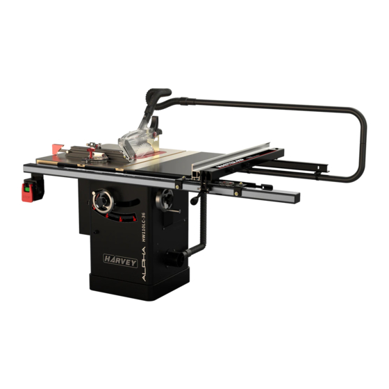
3.2 Features Identification 3.3 Optional Equipment Refer to Fig. 1. Sliding table Model: ST-1400S Fig. 1-1 Universal Overhead Guard Model: S-12S Fig. 1 Fig. 1-2 Left Extension Wing Miter Gauge Main Table Blade Guard Right Extension Wing Fence On/Off Switch Universal Mobile Base Motor Cover Model: MB-600... -
Page 9: Intended Use
3.4 Intended Use This table saw and the workpiece guide equipment supplied with it are intended to be used exclusively The machine is prohibited to be used in a for the following purposes: potentially explosive atmosphere! Laminated and unlaminated board materials (e.g. ●... -
Page 10: Safety Regulations
4. Safety Regulations 14. DISCONNECT MACHINES. Before servicing, when changing accessories or attachments; 4.1 General Safety Instructions 15. AVOID ACCIDENTAL STARTING. 1. KNOW YOUR MACHINE. Make sure the switch is in the “OFF” position Read and understand the owner’s manual and before plugging in;... -
Page 11: Residual Risks
5. STAND TO THE SIDE WHEN FEEDING 4.3 Residual Risks MATERIAL. Take precautions to reduce the hazard of Never stand or have any part of your body in line inhalation of harmful dust (e.g. wearing a dust with the path of the saw blade; mask);... -
Page 12: Installation Of The Machine
5. Installation of the Machine 5.2 Unpacking Your machine was carefully packaged for safe 5.1 Transportation of Machines transportation. Remove the packaging materials from around your machine and inspect it. If you 5.1.1 Transportation and store discover that the machine is damaged, please This machine has been well packaged and rust immediately call Customer Service for advice. -
Page 13: Contents
5.3 Contents The product is packed by four individual boxes as follows: Main machine box contents: (Fig. 5-1-----Fig. 5-4) A. Main table saw unitJJ..JJJ..JJJ1 B. Motor coverJJJ.JJ..JJJ..JJJ1 C. Left extension wingJJ..JJJJJJ1 D. Extension table (width 365 mm)JJJ1 Fig. 5-1 E. Saw bladeJJJJJJJJJJJJJ1 F. - Page 14 Fence box contents:(Fig. 5-5) Rail box contents:(Fig. 5-7) A. Fence bodyJ..J..JJJJJJ..JJ1 A. Rear railJJJJJ..JJJJJ..JJ1 B. FenceJJJJJJJJJJJJ..J..1 B. Front railJJJJJ.JJJJ..JJJ1 C. Front rail rectangular tubeJJJ...J1 D. Front rail tape scale (not shown)JJ.J1 Note : The assembly contains the corresponding hardware which is not shown in the figure, and can be checked with the exploded view.
-
Page 15: Installation
5.4 Installation 5.4.2 Hand-wheel handle installation Before beginning assembly, take note of the As shown in Fig. 7, install the hand-wheel to the following precautions and suggestions: cabinet by using the lock knob, then mount the FLOOR: Make certain that the floor is a level handle to the hand-wheel . - Page 16 fence and the blade, at the rear of the blade, to 5.4.4 Install the rail & extension table reduce the risk of workpiece binding or burning as 1. Install the rail and extension table as breakdown it is fed through the cut. shows.
- Page 17 5.4.5. Post the tape scale use the pointer 5.4.6 Install the switch F ig.14 ( ) The switch differs in different areas: window (Fig.13) North America area : F ig.14 (A) 。 European area : F ig.14 (B) 。 The machine features a Hi-Low fence with two pointer windows.
- Page 18 5.4.8 Install the blade guard 5.4.9 Extraction system 1. Slide the knurled knob out (refer to Fig. 16) and rotate it forward so it engages the upper bracket. A dust collection device should be used by the customer t he dust extraction equipment must ,...
- Page 19 5.4.11 Miter gauge installation This machine is equipped with the MG-36 Miter Gauge. This miter gauge is mainly used for guiding workpiece while cross cutting and miter cutting. Please refer to the MG-36 Miter Gauge Manual for detailed installation.. 5.4.12 Electrical installation Wiring should only be done by professional electricians.
- Page 20 ELECTRICAL DIAGRAM 2 HP, 60 Hz, 115/230 V, 1 PH 115 V Wiring Diagram 230 V Wiring Diagram Remark: 1. The colour of single core may differ with the illustration above in different areas. 2. Single-phase power supply range: 200-240 V. 3.
- Page 21 1.65 kW, 50 Hz, 230 V, 1 PH Remark: 4. The colour of single core may differ with the illustration above in different areas. 5. Single-phase power supply range: 200-240 V. 3. Meeting the CE standard, this electrical diagram is designed for European and Asian areas.
- Page 22 Rewiring for 230V Power (Note: This chapter is only available for the table saw with dual voltages.) The power must be disconnected before any wiring operations! This table saw can be used for 115V or 230V power. Fig. 21 It comes from the factory pre-wired for 115V, so if you want to use it for 230V, you need to take off the 2.
-
Page 23: Adjustment
6. Adjustment Before operation, Please make adjustments as followings: 6.1 Adjusting the Rip Fence Before using the rip fence, the parallelism and perpendicularity must be aligned correctly. Please refer to chapter 5.4.4 Install the rail & fence. Fig. 24 6.2 Aligning the Table T-slot Parallel with 6.3 Adjusting the 45°... -
Page 24: Aligning The Riving Knife With Blade
6.4 Aligning the Riving Knife with Blade greater than the saw blade plate. As shown in Fig. The riving knife must be aligned with the blade. If not properly aligned, the riving knife will force the workpiece sideways during the cut, increasing the risk of kickback. -
Page 25: Operations
7. Operations 7.1 Electrical Operation Two types of the switches are alternative for your machine, the actual object shall prevail. Refer to Fig. 30 & Fig.31 “ON” Button: Start the machine. “OFF” Button: Stop the machine. Hole for Safety Lock: While not using the machine, insert the safety pin to prevent accidental start Fig. -
Page 26: Ripping
7.4 Ripping 8. Maintenance "Ripping" means cutting with the grain of a natural This table saw has TEFC motor and sealed wood workpiece. In other man-made materials lubricated bearings, which requires very little such as MDF or plywood, ripping simply means maintenance other than minor lubrication and cutting lengthwise. -
Page 27: Trouble Shooting
9. Trouble Shooting PROBLEM SOLUTION SAW WILL NOT START 1. Saw not plugged in. 1. Plug in saw. 2. Fuse blown or circuit breaker tripped. 2. Replace fuse or reset circuit breaker. 3. Cord damaged. 3. Have cord replaced by a certified electrician. OVERLOAD KICKS OUT FREQUENTLY 1. -
Page 28: Exploded View And Parts List
10. Exploded View and Parts List Table Saw Body Exploded View... - Page 29 Body Assembly Parts List REF# DESCRIPTION REF# DESCRIPTION Extension table Lock washer 5 Cap screw M8-1.25 x 35 Button HD screw M5-.8 x 12 Lock washer 8 Lead screw bracket Flat washer 8 Button HD screw M5-.8 x 16 Table insert (standard) Lock nut M8-1.25 Set screw Tilt scale...
- Page 30 Trunnion Assembly Exploded View...
- Page 31 Trunnion Assembly Parts List REF# DESCRIPTION REF# DESCRIPTION REF# DESCRIPTION Lock nut M16-2 Flat HD screw M10-1.5 x 40 Button HD screw M5-.8 x 12 Flat washer 16 Spacer Button HD screw M4-.7 x 8 Cap screw M8-1.25 x 20 Spacer (Nylon) Motor locationshaft Lock washer 8...
- Page 32 Blade Guard Exploded View GLIDER Saw Blade Guard (UL62841) DESCRIPTION DESCRIPTION Pan HD screw M4-0.7x12 Nickel Pan HD screw M4-0.7x28 Nickel Plastic spacer Spreader Left guard Right guide block Guard support Left guide block Left cover Roller Plastic liner Bearing 689ZZ Front guard Right cover Cap screw M3-0.5x8 Nickel...
- Page 33 Fence Exploded View DESCRIPTION DESCRIPTION Glide pad Lock knob for Low Fence Special locking nut M12-1.75 Lock knob for High Fence Set screw M12-1.75x16 Window fixing block Set screw M12-1.75x10 Window Hex bolt M6-1x40 Window bracket Cam foot Fence end cap Lock nut M6-1 Set screw M12-1.75x30 Hex bolt M10-1.5x45...
- Page 34 36″Rail & Extension Table Exploded View 36″Rail & Extension Table Parts List REF# DESCRIPTION REF# DESCRIPTION Tube cover Flat big washer 8 Tube Lock washer 8 Front rail Hex nut M8-1.25 Scale Rear rail Flat washer 6 Cap screw M6-1 x 16 Lock washer 6 Cap screw M8-1 x 40 Cap screw M6-1x16...
- Page 35 Switch Exploded View Switch (UL62841): DESCRIPTION DESCRIPTION Safety pin O type terminal Chain Switch bracket Tapping screw M3.5x19 Tapping screw M3.5x10 Switch Spring terminal Switch box Overload protection switch Pan HD screw M4-0.7x8 Strain relif PG13.5 Lock washer 4 Cable for power supply Flat washer 4 Cable for motor Note: The Power switch and circuit breaker used for voltage conversion (115V/230V) are provided with the...
- Page 36 Over Arm Exploded View DESCRIPTION DESCRIPTION Flexible hose (1-1/2” 0.6m) Lock washer 6 Hose Connector 1-1/2" Bracket Over arm Flexible hose (1-1/2” 1m) Cap screw M6-1x16 Clamp Flat washer 6 Cap screw M6-1x12...
-
Page 37: Certificates
11. Certificates...
Need help?
Do you have a question about the HW110LC-36 and is the answer not in the manual?
Questions and answers