
Related Manuals for HARVEY HW110TC


Summary of Contents for HARVEY HW110TC
- Page 1 Revision A 2022-01-18 INSTRUCTION MANUAL Original Instructions 10″ Cabinet Table Saw MODEL:HW110TC...
-
Page 3: Table Of Contents
Contents 1. Foreword............................... 1 2. Warranty Information.........................1 3. Machine Description.......................... 2 3.1 Technical Parameters......................... 2 3.2 Features Identification.........................4 3.3 Optional Equipments........................4 3.4 Intended Use..........................5 3.5 Requirements of Electrical Power..................... 5 4. Safety Regulations..........................6 4.1. General Safety Instructions.......................6 4.2. Specific Safety Instructions for Sliding Table Saw..............6 4.3. - Page 4 1.前言................................ 24 2.质保信息..............................24 3.设备描述..............................25 3.1 技术参数............................. 25 3.2 产品组成............................. 26 3.3 可选配件............................. 26 3.4 产品应用............................. 27 3.5 电力要求............................. 27 4. 安全条例.............................. 28 4.1.通用安全条例..........................28 4.2.台锯安全条例..........................28 4.3.残余风险............................29 4.4.安全附件............................29 5. 设备安装.............................. 29 5.1 设备的运输和储存........................29 5.2 拆包............................. 30 5.3 包装清单............................. 30 5.4 安装.............................
- Page 5 English Version...
-
Page 6: Foreword
1. Foreword 2. Warranty Information This manual contains basic information Limited Warranty qualified operating staff describes Two years. surroundings and using ways of the machine for Proof of Purchase those it is intended. It contains also all necessary Please keep your dated proof of purchase for information for a correct and safe operating. -
Page 7: Machine Description
Fence Type T-Square High and Low Fence Fence Fence Size 3-3/8” x 1-7/8” (85.5 x 48.5 mm) Finishing Powder Coated Other Information Dust Port Size 4”(100 mm) Remark: Precision ground cast iron table, the Model number contains “P”. Example: HW110TC-36P, HW110TC-52P. - Page 8 CE Version Saw Blade Guard Fence Type T-Square High and Low Fence Fence Fence Size 85.5 x 48.5 mm Finishing Powder Coated Other Information Dust Port Size 100 mm Remark: Precision ground cast iron table, the Model number contains “P”. Example: HW110TC-36P, HW110TC-52P.
-
Page 9: Features Identification
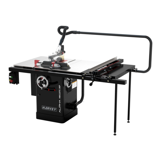
3.2 Features Identification 3.3 Optional Equipment Refer to Fig. 1. Sliding table Model: ST-1400S Fig. 1-1 Universal Overhead Guard Model: S-12S Fig. 1 Left Extension Wing Fig. 1-2 Blade Guard Main Table Right Extension Wing Fence Assembly Extension Table Rail Assembly Support Leg Universal Mobile Base Motor Cover... -
Page 10: Intended Use
3.4 Intended Use This table saw and the workpiece guide equipment supplied with it are intended to be used exclusively The machine is prohibited to be used in a for the following purposes: potentially explosive atmosphere! Laminated and unlaminated board materials (e.g. ●... -
Page 11: Safety Regulations
4. Safety Regulations 14. DISCONNECT MACHINES. Before servicing, when changing accessories or attachments; 4.1 General Safety Instructions 15. AVOID ACCIDENTAL STARTING. 1. KNOW YOUR MACHINE. Make sure the switch is in the “OFF” position Read and understand the owner’s manual and before plugging in;... -
Page 12: Residual Risks
4.3 Residual Risks 5. STAND TO THE SIDE WHEN FEEDING MATERIAL. Take precautions to reduce the hazard of Never stand or have any part of your body in line inhalation of harmful dust (e.g. wearing a dust with the path of the saw blade; mask);... -
Page 13: Installation Of The Machine
5. Installation of the Machine 5.2 Unpacking Your machine was carefully packaged for safe 5.1 Transportation of Machines transportation. Remove the packaging materials from around your machine and inspect it. If you 5.1.1 Transportation and store discover that the machine is damaged, please This machine has been well packaged and rust immediately call Customer Service for advice. -
Page 14: Contents
(Fig. 5-1-----Fig. 5-5) Main table saw unit Motor cover Left extension wing Fig. 5-2 Right extension wing Extension table (width 365 mm) (Only for HW110TC-52) Extension table (width 505 mm) Hand wheel Lock knob Dado table insert Push stick Wrench open-end Fig. - Page 15 Fig. 5-7 Note: There are two types of the guide rails, please have a check according to the name plate of the machine: 1. 36” guide rail is for HW110TC-36. 2. 52”guide rail is for HW110TC-52.
-
Page 16: Installation
5.4 Installation 5.4.2 Hand-wheel handle installation Before beginning assembly, take note of the As shown in Fig. 7, install the hand-wheel to the following precautions and suggestions: cabinet by using the lock knob, then mount the FLOOR: Make certain that the floor is a level handle to the hand-wheel . - Page 17 fence and the blade, at the rear of the blade, to 5.4.4 Install the rail & extension table reduce the risk of workpiece binding or burning as 1. Install the rail and extension table as breakdown it is fed through the cut. shows.
- Page 18 5.4.5. Post the tape scale use the pointer 5.4.6 Install the switch ( Fig.14 ) The list above doesn’t cover all the countries, the window (Fig.13) actual object shall prevail. The switch is mounted on the lower right side of the The machine features a Hi-Low fence with two pointer windows.
- Page 19 5.4.8 Install the blade guard 5.4.9 Extraction system 1. Slide the knurled knob out (refer to Fig. 16) and rotate it forward so it engages the upper bracket. A dust collection device should be used by the customer,the dust extraction equipment must be switched on before commencing machining.
- Page 20 Fit the over arm to the rear rail (Fig.18-3): 5.4.12 Electrical installation 1. Fit the bracket (A) to the rear rail with screw B. 2. Fit the over arm to the bracket (B) with clip (C). (Total 2 sets of clasps) Wiring should only be done by professional 3.
- Page 21 ELECTRICAL DIAGRAM 2.2 kW, 60Hz,230 V, 1 PH Remark: 1. The colour of single core may differ with the illustration above in different areas. 2. Single-phase power supply range: 200-240 V. 3. Meeting the standard of UL62841, this electrical diagram is designed for North-American areas. 4.
- Page 22 2.2 kW, 50Hz,230 V, 1 PH Remark: 1.The colour of single core may differ with the illustration above in different areas. 2.Single-phase power supply range: 200-240 V. 3.Meeting the CE standard, this electrical diagram is designed for European and Asian areas. 4.
-
Page 23: Adjustment
6. Adjustment Before operation, Please make adjustments as followings: 6.1 Adjusting the Rip Fence Before using the rip fence, the parallelism and perpendicularity must be aligned correctly. Please refer to chapter 5.4.4 Install the rail & fence. Fig. 24 6.2 Aligning the Table T-slot Parallel with 6.3 Adjusting the 45°... -
Page 24: Aligning The Riving Knife With Blade
6.4 Aligning the Riving Knife with Blade greater than the saw blade plate. As shown in Fig. The riving knife must be aligned with the blade. If not properly aligned, the riving knife will force the workpiece sideways during the cut, increasing the risk of kickback. -
Page 25: Operations
7.3 Crosscutting 7. Operations "Crosscutting" means cutting across the grain of 7.1 Electrical Operation a natural wood workpiece. In other man-made materials, such as MDF or plywood, crosscutting The actual object shall prevail. Refer to Fig.31 means cutting across the width of the workpiece. “ON”... -
Page 26: Maintenance
8. Maintenance This table saw has TEFC motor and sealed lubricated bearings, which requires very little maintenance other than minor lubrication and cleaning. Please do the maintenance as following contents. LUBRICATION Clean off the wood chips on the worm gears and trunnions and apply the grease to keep them lubricated. -
Page 27: Trouble Shooting
9. Trouble Shooting PROBLEM SOLUTION SAW WILL NOT START 1. Saw not plugged in. 1. Plug in saw. 2. Fuse blown or circuit breaker tripped. 2. Replace fuse or reset circuit breaker. 3. Cord damaged. 3. Have cord replaced by a certified electrician. OVERLOAD KICKS OUT FREQUENTLY 1. - Page 28 中文版本...
-
Page 29: 质保信息
1. 前言 2. 质保信息 本说明书与机器一起交付给客户。 说明书包含对 质保期限 操作人员的要求、 机器的适用环境以及正确安全的操 两年。 作方法,但不包含全部的安全要求。在使用之前,操 作人员必须仔细阅读并理解本说明书, 才能有效的避 购买凭证 请保留有效的购买凭证, 以作保修及维修之用。 . 免错误的安装和操作,保证人身安全。 质保范围 自客户购买本产品之日起, 本公司将向原始零售 客户提供为期两年的质保服务, 在质保期内, 产品因 质量缺陷造成的维修是免费的。 以下原因造成的事故、故障等在保修范围以外: ◆ 滥用、误用、疏忽引起的事故。 ◆ 缺乏维护导致的故障。 ◆ 非授权维修改造。 ◆ 正常磨损部件。 ◆ 天灾、火灾、爆炸引起的故障。... -
Page 30: 设备描述
3.设备描述 3.1 技术参数 HW110TC-36(P) HW110TC-52(P) 型号 235 kg 250 kg 重量 1795x1265x1225 mm 2160x1265x1225 mm 产品尺寸 长度/宽度/高度 514x498mm 占地面积 开关 开关类型 电磁过载保护开关 TEFC,电容启动,感应电机 类型 2.2 kW, 230 V, 1 PH, 14 A 马力,电压,电相,电流 电机 2800 RPM 转速 动力传输 多锲带 250mm 最大锯片直径... -
Page 31: 产品组成
3.2 产品组成 3.3 可选配件 参考图 1。 滑台 型号 ST-1400S 图 1-1 “鲨鱼”护罩 型号 S-12S 图 1 图 1-2 左副台板 锯片护罩 主台板 右副台板 靠山组件 延伸台板 万能移动小车 导轨组件 型号 MB-600 支腿 电机罩 箱体 锯片升降手轮 图 1-3 锯片倾角手轮 开关 量角器 悬臂集尘(系统) 注意: 图 1 仅为示意,具体以实物为准。... -
Page 32: 产品应用
3.4 产品应用 此台锯和随机配备的附件仅用于以下用途: 此设备禁止用于存在潜在爆炸风险的环境中。 层压板或非层压板材料(例如刨花板、 夹芯板、 MDF ● 3.5 电力要求 板等。) 实心板 ● 电机使用及预接电压 石膏板、硬纸板、可以使用夹具的胶合板。 ● 电机 描述 塑料(热固性塑料,热塑性塑料)。 2.2 kW ● 230 V 电压(V) 1 PH 电相 刀具 频率( Hz) 50 Hz 所选锯片必须适合所加工的材料。 ● 14 A 电流(A) 主 锯 片 的 材 料 为 实 心 铬 钒 (CV) 或 碳 化 钨 合 金 ●... -
Page 33: 安全条例
4.安全条例 14.断开电源 在进行保养、 更换配件或者附件时, 确保设备电源已 4.1 通用安全条例 断开。 1.认识您的设备 15.避免意外启动 阅读并掌握该产品的说明书以及机器标贴的说明, 学 确保设备在接入电源前。开关处于”OFF”位置。 16.使用推荐的配件 习设备的应用,了解设备的局限性和具体的潜在风 险。 使用说明书推荐的配件, 使用不合适的配件可能会造 2.设备接地 成意外的发生。 17.切勿站在设备上 接地可大大降低发生电击的风险。 3.保持锯片护罩在适当位置 设备倾倒会造成严重的伤害, 不要将木料摆放在需要 正确安装锯片护罩,使其处于良好的工作状态。 站上台锯才能取到的地方。 4.移除调节工具 18.检查受损部件 养成良好的习惯, 在启动设备前检查扳手等调节工具 在使用设备前, 应仔细检查安全部件是否损坏, 以确 是否全部移除。 保在操作时, 这些部件能够发挥正常的保护作用。 安 5.保持工作区域的干净整洁 全部件出现损坏时,应及时正确地进行修理或者更 凌乱的工作区域或者工作台会增加意外事故发生的... -
Page 34: 残余风险
4.4 安全附件 7.横切靠山的安全操作 在进行横切时,应移开纵切靠山。 锯切窄工件时,必须使用推料块。必要时,将工 8.确保正确的进料方向 件靠住靠山。 如图 2 所示, 用户可以自制简易推料块。 锯切小于 4-3/4”(120 mm)的工件时,必须使用 进料方向应与锯片旋转方向相反。 9.正确使用靠山 推料把手,如图 3 所示,以防手部距离锯片过近。 不允许同时使用横切及纵切靠山进行定位。 10.切断电源 在更换锯片前,确保已切断电源。 11.提供足够的支撑 图 2 裁切宽长的木料时, 应在机器侧面或后面提供足够的 支撑.。 12.避免木料回弹 通过保持锯片锋利,锯片与直靠尺平行,锯片护罩、 劈刀板处于正确位置, 锯切过程中紧握木料, 不直切 无直导向边的木料等方法,来避免木料回弹的发生。 13.避免处于别扭的位置 图 3 操作时, 避免身体处于别扭的位置, 以防止身体突然 滑到,导致手部接触到正在转动的锯片。... -
Page 35: 包装清单
D . 右 副 台 板 … ....… … . . … … … 1 E. 延伸台板(宽度 365mm)…………..…………1 (仅适用于HW110TC-52) F. 延伸台板(宽度 50 5 m m )… ..…… … … 1 G .手轮…......……..…..………..………1... - Page 36 D. 刻 度 尺 … … ....… … . … … . … 1 E. 支 腿 … . . … … . . . … … … … … … … … 2 备注: 该组件包含对应的安装标准件,图中未显示, 可对照爆炸图进行标准件的核对。 图 5-7 备注: 导轨型号有 2 种,对照设备铭牌标识进行核对: 1. 36”导轨组件,对应型号: HW110TC-36。 2. 52”导轨组件,对应型号: HW110TC-52。...
- Page 37 5.4.2 安装手轮把手 5.4 安装 如图 7 所示, 通过锁紧旋钮将手轮安装到主机上, 然 安装前,检查以下事项: 后装上手轮把手。 地面: 该设备对地面无特殊要求,保证地面平整即 可。 空间要求: 该设备对空间无特殊要求, 保证设备前后 锁紧旋钮 有足够空间用于工件的送料和出料即可。 插座放置: 应将插座放置在离设备尽可能近的地方, 以防电源线绊倒操作者。 在组装设备前,需仔细阅读和理解说明书,并 把手 确保设备电源未接通,设备开关处于关闭位置。 如图 6-1 所示, 将开关从箱体内拉出, 并移除运 图 7 输吊架。 5.4.3 副台板安装 (图 8 ) 机器主台板两侧各配备了一块铸铁副台板。 副台 板的安装螺钉已经预装在主台板侧面的螺纹孔中。...
- Page 38 5.4.4 导轨、靠山、延伸台板安装 1. 参考爆炸图进行导轨、延伸台板的安装。 锁紧后导轨之前,确保后导轨上平面低于 T 型 槽(如图 9),避免影响量角器的使用。 锁紧延伸台板前,确保延伸台板与主台板共面。 图 11 6. 调节靠山的平行度及垂直度(图 12) 如靠山、锯片与 T 型槽之间不平行,或者靠山 与台板不垂直,按以下描述进行调节。 a.T 型槽与锯片平行度的校准: 图 9 在校准靠山平行度或垂直度前,必须校准 T 型 2. 将靠山安装到锯片右侧导轨上,如图 10 所示。 槽与锯片的平行度, 参考章节 6.2 台板 T 型槽与锯片 的平行度校准。 b.靠山与 T 型槽或锯片的平行度校准: 在放置导轨前,确保锁紧压片与靠山锁紧把手...
- Page 39 5.4.5.刻度尺的张贴及视窗的使用(图 13) 5.4.6 安装开关(图 14) 电磁开关通过两组螺钉进行固定, 安装在导向管 右侧下方,安装标准件预装在导向管上,如图 14 所 在张贴刻度尺前,必须完成靠山平行度及垂直 度的校准。 示。 该设备配备高低靠山, 为方便使用, 配置两个刻 度视窗,分别对应高靠山和低靠山的位置读取,如 图13 所示;2 个视窗的位置均可独立调整;视窗 (A)对应低靠山的使用,视窗(B)对应高靠山的 使用。松开旋钮(C)或者(D),可以微调刻度视 窗的位置。 刻度尺的张贴: 将靠山设置为高靠山模式, 滑动靠山, 高靠山贴 住锯片,然后锁紧。如图 13 所示,将刻度尺放置在 图 14 靠山导向管上,确保刻度尺与导管平行,并且 0 刻 度处位于视窗(B)红线的正下方。然后用铅笔在导 5.4.7 安装锯片 向管上标记 0 刻度的位置,移除靠山并撕开刻度尺 1.移除锯片保护板。...
- Page 40 5.4.8 安装锯片护罩 1.向外拨动滚花旋钮(参考图 16),然后将滚花旋 钮压向支架。 Fig.18-1 图 16 2.插入锯片护罩劈刀板,拨动滚花旋钮,使锁紧销穿 过劈刀板上的安全限位孔。 3.安装效果如图 17 所示。 Fig.18-2 悬臂集尘的安装(图 19): a.用螺丝(B)将支架(A)装到后导轨上。 b.用管夹(C)将悬臂固定到支架(A)上。 (共计 2 套管夹) c.将随机提供的软管(1.5”)连接到集尘口上。 注意: 此步骤所用到的五金件都预装在悬臂集尘组 件上。 图 17 在操作设备前,检查锯片是否锁紧。 向上提拉劈刀板,检查劈刀板是否被有效安装。 5.4.9 集尘系统的安装 用户应使用集尘设备,在启动设备开始操作前, 悬臂 必须开启集尘设备。 图 19 如图18-1所示, 将出尘口先固定在箱体上, 然后 设备连接的集尘器要求: 将波纹管与出尘口进行连接,如图18-2所示。...
- Page 41 5.4.10 安装电机罩 将电机罩安装到箱体上,如图 20 所示。 电气原理图 2.2kW, 230 V, 1 PH, 14 A 图 20 5.4.11 安装量角器 该设备配备了 MG-36 量角器。该量角器主要用 于工件的横切和斜切的定位。 有关量角器的详细信息,请参阅 MG-36 量角器 说明书。 5.4.12 电气安装 备注: 1. 由于地区差异,电缆单芯线的颜色与图示可能有 电气安装只能由有资质的电工完成。 差异。 确保设备正确接地,所有可触摸到的导电部件 2. 单相供电电压区间:200-240V 都应连接到地线。 终端用户的供电,必须配备过电压保护装置。 设备供电配电箱应安装断路器,以防止操作人 员受到间接冲击的电击。 检查机器铭牌上显示的机器电压和频率与供电 是否匹配。...
-
Page 42: 调节纵切靠山
6.3 调节 45°和 90°限位 6.调节 锯片倾角机构设置了 45°和 90°的限位,如图 23 中圆圈所示,该限位在出厂前已经调节好,如锯 片定位角度出现偏差,可打开电机罩重新调节。 设备在正式使用前,须进行以下调节: 90°限位的调节: 打开设备左侧的电机箱门, 松 开内六角螺钉(B),转动 90°摆角限位的位置进行调 6.1 调节纵切靠山 节,确定后锁紧内六角螺钉(B)。 纵切靠山在使用前, 须对平行度及垂直度进行调 45°限位的调节: 拧松设备右侧的维护盖板的螺 节,有关纵切靠山的调节,请参考章节“5.4.4 安装 丝,取下箱门,拧松内六角螺钉(A),转动 45°摆角 导轨和靠山”。 限位的位置进行调节,确定后锁紧内六角螺钉(A)。 6.2 台板 T 型槽与锯片的平行度校准 台板 T 型槽必须与锯片保持平行。先用组合角 尺测量 T 型槽到锯片后端锯齿的距离。然后将锯片 逆时针旋转... -
Page 43: 电气操作
如需校准,请参考图 25,按以下步骤进行调节: 7.操作 1.切断设备电源; 2.移除台面保护板; 7.1 电力操作 3.松开上下螺钉(B),然后通过旋进或旋出紧定螺 如图 28 所示。 钉(A),微调劈刀板的位置,校准完成后锁紧螺钉 ON 按钮:启动设备。 (A)和(B)。 OFF 按钮:关闭设备。 4.重新安装台面保护板。 。 安全锁孔:不使用时,插入安全销,防止意外启动 图 25 图 28 7.2 锯片升降和摆角的调节 1.劈刀板材质必须是极限抗拉强度为 580N/mm²的 锯片升降调节:松开锁紧旋钮(C),如图 29 所示, 钢材或者相同强度的材料,侧面须平整(每 100mm 转动升降手轮(D),调整锯片高度,调整完成后锁 误差在 0.1mm 之内),厚度必须小于一个锯路的宽 紧旋钮 (C) 。 锯片应被升至高于被锯切木料表面 1/8” 度,并且至少比锯片本体厚... - Page 44 7.3 横切 8.维护 横切是指垂直于天然木料纹理的锯切。 对于其他 此款台锯的电机为全密封电机, 主轴轴承采用免 的人造材料,比如 MDF 板或者胶合板,横切是指对 维护轴承, 只需要极少的维护工作, 如少量的润滑和 工件的短边进行锯切。 清洁。请按以下内容对设备进行维护: 台锯上的横切需要使用量角器组件来进行定位 和导向,量角器组件必须放在台板的 T 型槽内使用。 润滑 开始横切时, 应缓慢移动工件, 并在移动过程中, 清理涡轮蜗杆上的木屑,涂上润滑脂进行润滑, 握紧工件, 使其紧贴量角器组件和台面。 在锯切过程 每周一次。 中, 绝不能直接松开锯切的工件或者去拿已经切掉的 木料。握住支撑的工件,而不是握住被锯掉的部分。 清洁 送料直到工件被切为 2 截, 再将量角器组件和留下的 及时清理台面及内腔的木屑。 工件一起拉回原位。 注意在回拉工件前, 可略微施力 每日一次。...
-
Page 45: 常见问题
9.常见问题 问题描述 解决方法 台锯无法启动 1.未接入电源。 1.将台锯接入电源 2.保险丝烧断或断路器跳闸。 2.更换保险丝或者重置断路器。 3.电源线损坏。 3.更换电源线。 频繁过载停机 1.电源线过长或者线规过小。 1.更换合适线规或长度的电源线。 2.进料速度过快。 2.降低进料速度。 3.锯片出现问题(钝了、弯曲、粘有胶质物体)。 3.清理或者更换锯片。 4.木料与纵切靠山发生挤压。 4.检查并调节纵切靠山与锯片的平行度。 5.木料弯曲造成锯片挤压。 5.选择另一块木料。 6.使用的电流过低 6.联系电力公司. 不能精准地进行 45°和 90°的纵切。 1.限位调节不正确。 1.用直角尺检查锯片位置,并调节限位。 2.倾角指针设置不正确.。 2.用直角尺检查锯片位置,并对指针进行调节。 纵切时,木料挤压锯片 1.纵切靠山没有和锯片进行校准。 1.检查并调节纵切靠山。 2.木料弯曲。 2.选择另一块木料。 木料与劈刀板发生挤压 1.劈刀板的位置没有校准。 1.检查并校准劈刀板与锯片的相对位置。 锯切效果不理想 1.锯片钝了。 1.更换锯片... -
Page 46: Exploded View And Parts List
Exploded View and Parts List (爆炸图和部件清单) Table Saw Body Exploded View... - Page 47 Body Assembly Parts List REF# DESCRIPTION REF# DESCRIPTION Left extension table Handwheel bearing seat Cap screw M8-1.25 x 35 Cap screw M5-.8 x 16 Lock washer 8 Lock nut M8-1.25 Flat washer 8 Tilt scale Table insert (standard) Lock nut M3-.5 Set screw Upper and lower hinge Button HD screw M5-.8 x 16...
- Page 48 Trunnion Assembly Exploded View...
- Page 49 Trunnion Assembly Parts List REF# DESCRIPTION REF# DESCRIPTION REF# DESCRIPTION Stop collar Lock nut M16-2 Spacer Int retaining ring 24 Flat washer 16 Spacer (Nylon) Cap screw M8-1.25 x 20 Cap screw M6-1 x 35 Tilt leadscrew nut Tilt leadscrew base Lock washer 8 Shaft bracket Tilt leadscrew...
- Page 50 Blade Guard Exploded View GLIDER Saw Blade Guard (UL62841) DESCRIPTION DESCRIPTION Pan HD screw M4-0.7x12 Nickel Pan HD screw M4-0.7x28 Nickel Plastic spacer Spreader Left guard Right guide block Guard support Left guide block Left cover Roller Plastic liner Bearing 689ZZ Front guard Right cover Cap screw M3-0.5x8 Nickel...
- Page 51 Fence Exploded View DESCRIPTION DESCRIPTION Glide pad Lock knob for High Fence Special locking nut M12-1.75 Lock knob for Low Fence Set screw M12-1.75x16 Window fixing block Set screw M12-1.75x10 Window Hex bolt M6-1x40 Window bracket Cam foot Fence end cap Lock nut M6-1 Set screw M12-1.75x30 Hex bolt M10-1.5x45...
- Page 52 36″Rail & Extension Table Exploded View DESCRIPTION DESCRIPTION Tube cover Hex nut M8-1.25 602-1 Tube (36") 612-1 Rear rail (36") 603-1 Front rail (36") Cap screw M8-1.25x40 604-1 Scale(36”) Cap screw M6-1x16 Flat washer 6 Flat washer 8 Lock washer 6 Pan HD screw M8-1.25x40 Cap screw M6-1x16 Support leg...
- Page 53 52″Rail & Extension Table Exploded View DESCRIPTION DESCRIPTION Tube cover 612-2 Rear rail (52") 602-2 Tube (52") Cap screw M8-1.25x40 603-2 Front rail (52") Cap screw M6-1x16 604-2 Scale Flat washer 8 Flat washer 6 Pan HD screw M8-1.25x40 Lock washer 6 Support leg Cap screw M6-1x16 Foot...
- Page 54 Switch Exploded View DESCRIPTION DESCRIPTION Switch Lock washer 5 Switch bracket Flat washer 5 Chain Cable for power supply Safety pin Cable for motor Pan HD screw M5-0.8x12...
- Page 55 Over Arm Exploded View DESCRIPTION DESCRIPTION Flexible hose (1-1/2” 0.6m) Lock washer 6 Hose Connector 1-1/2" Bracket Over arm Flexible hose (1-1/2” 1m) Cap screw M6-1x16 Clamp Flat washer 6 Cap screw M6-1x12...
Need help?
Do you have a question about the HW110TC and is the answer not in the manual?
Questions and answers