Table of Contents
Advertisement
Advertisement
Table of Contents

Related Manuals for HARVEY C200 Series


Summary of Contents for HARVEY C200 Series
-
Page 2: Table Of Contents
Contents 1. Foreword............................... 1 2. Warranty Information.........................1 3. Machine Description.......................... 2 3.1 Technical Parameters......................... 2 3.2 Features Identification.........................3 3.3 Optional Equipments........................3 3.4 Intended Use..........................4 3.5 Requirements of Electrical Power..................... 4 4. Safety Regulations..........................5 4.1. General Safety Instructions.......................5 4.2. -
Page 3: Foreword
Defective parts will be repaired or its functions before operating it. replaced by Harvey at no charge. Warranty does not apply to defects due directly or indirectly to misuse, abuse, normal wear and tear, negligence... -
Page 4: Machine Description
3. Machine Description 3.1 Technical Parameters Model: C200-30 ITEM C200-30 Weight 180Kg 396 lbs Product Length/Width/Height 1570x985x1060 mm 61-13/16"×38-3/4"×41-3/4" Dimensions Footprint 514x498 mm 20-1/4"×19-5/8" Electrical Switch Magnetic with Thermal Overload Protection Power Horsepower, Voltage, 1.65 kW, 230 V, 2.0 HP, 115 V (230 V), 60 Hz, Supply Frequency, Phase, Amps 50 Hz, 1 PH, 8 A... -
Page 5: Features Identification
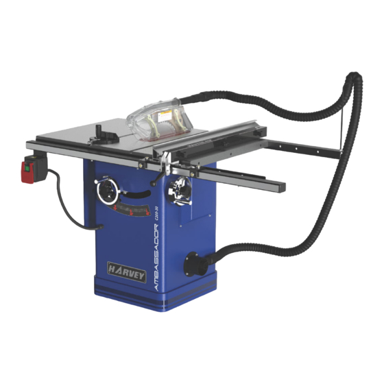
3.2 Features Identification 3.3 Optional Equipments Refer to Fig. 1. Sliding table Model: ST-1400S Fig. 1-1 Universal Mobile Base Model: MB-600 Fig. 1 Fig. 1-2 Left Extension Table Miter Gauge Main Table Blade Guard Fence Right Extension Table Flexible hose Rail &... -
Page 6: Intended Use
3.4 Intended Use The table saw and the fence supplied with it are intended to be used exclusively for the following The machine is prohibited to be used in a purposes: potentially explosive atmosphere! Laminated and unlaminated board materials (e.g. ●... -
Page 7: Safety Regulations
14. DISCONNECT MACHINES. 4. Safety Regulations Before servicing, when changing accessories or attachments; 4.1 General Safety Instructions 15. AVOID ACCIDENTAL STARTING. 1. KNOW YOUR MACHINE. Make sure the switch is in the “OFF” position Read and understand the owners manual and before plugging in;... -
Page 8: Residual Risks
5. STAND TO THE SIDE WHEN FEEDING 17. CHECK MATERIAL. Periodically check the brake function to make sure Never stand or have any part of your body in line the completed stop time of the saw blade is less with the path of the saw blade; than 10 seconds. -
Page 9: Installation Of The Machine
5. Installation of the Machine 5.2 Unpacking Your machine was carefully packaged for safe 5.1 Transportation of Machines transportation. Remove the packaging materials from around your machine and inspect it. If you 5.1.1 Transportation and Storage discover machine damaged, please Anti-rust and shock-proofing measures were taken immediately call Customer Service for advice. -
Page 10: Contents Of C200-30
5.3 Contents of C200-30 Main machine box contents: (Fig. 4-1-----Fig. 4-4) A. Main table saw unit……..………..………1 B. Motor cover……….……..………..………1 C. Left extension table……..………………1 D. Right extension table…………………1 E. Saw blade…………………………………1 Fig. 4-1 F. Blade guard assembly…………………1 G. Riving knife……..………..……..………1 H. Hand wheel……………..………..………1 I. -
Page 11: Safety Measure Before Installation
Fence box contents:(Fig. 4-5) Rail box contents:(Fig. 4-7) A. Fence body…..…..………………..……1 A. Rear rail……………..……………..……1 B. Fence………………………………..…..1 B. Front rail…………….…………..………1 C. Front rail rectangular tube………...…1 D. Front rail tape scale………………….…1 Fig. 4-5 Fig. 4-7 Flexible hose box contents:(Fig. 4-6) A. Flexible hose (length 2.5 m)…………...1 B. -
Page 12: Installation
5.5 Installation 5.5.3 Hand wheel handle install Before beginning assembly, take note of the Install the handle into the Blade Tilt & Elevation following precautions and suggestions. The machine is bolted to the pallet, before hand wheel as shown in Fig. 6. attempting any of the assembly procedures remove all of the loose parts and hardware from the inside of the machine and unbolt the machine... - Page 13 3. Checking fence parallelism 5.5.5 Install the rail & fence Refer to Fig. 10. 1. Install the rear rail , front rail, tube, and extension ----Slide the fence along the rail , if it drags across table. Before tightening the fasteners,check to the table, then adjust the foot at the rear of the make sure the top edge of rear rail is flush with the fence to raise the fence off of the table just enough,...
- Page 14 Slide the fence up against the saw blade, and lock 5.5.8 Install the blade guard it in place; Place the front rail tape scale on the fence tube, make sure it is parallel with the tube, 1. Reinstall the insert, slide the knurled knob out and the “0”...
- Page 15 4. Place a straightedge against the blade and the 3. The highest point of the riving knife must be set spreader. When properly aligned, beneath the topmost teeth. spreader/riving knife will be in the "alignment 5.5.9 Extraction system zone," refer to Fig. 16, and will be parallel with the blade.
- Page 16 5.5.10 Electrical installation Check that the voltage and frequency required by Wiring should only be done by professional the machine, which is shown on the machine’s electricians. Always make sure the machine is name plate, corresponds to the electric power properly grounded.
- Page 17 Rewiring for 230V Power (Note: This chapter is only available for the table saw with dual voltages.) The power must be disconnected before any wiring operations! This table saw can be used for 115V or 230V power. Fig. 21 It comes from the factory pre-wired for 115V, so if you want to use it for 230V, you need to take off the 2.
-
Page 18: Adjustment
and adjusting the set screws (C) the same amount. 6. Adjustment Make sure the fence remains parallel with the table T-slot. Retighten lock nuts. Before operation, the machine should be 3. To set the fence perpendicular to the table, place carefully adjusted for the best performance. -
Page 19: Adjusting 45°And 90°Positive Stops
If an adjustment is necessary, loosen the screws 6.4 Adjusting 45°and 90°Positive Stops which are fixed to the table (as indicated by the The tilt mechanism has adjustable stops for vertical pointing arrows) and make the needed adjustment and 45°. The machine comes factory-set but should until both measurements are equal or less than 0.2 adjustment be required, loosen and adjust the stops mm. -
Page 20: Operations
7.4 Crosscutting 7. Operations Crosscutting requires the use of the miter gauge to 7.1 Electrical Operation Fig. 27 position and guide the work. Place the work against the miter gauge and advance both the miter gauge ON Button: Starts the motor. and work toward the saw blade. -
Page 21: Maintenance
8. Maintenance CHANGING BELTS This table saw requires very little maintenance other WARNING: MAKE SURE THE POWER CORD IS than minor lubrication and cleaning. The following DISCONNECTED FROM THE POWER SOURCE! sections detail what will need to be done in order to 1. -
Page 22: Trouble Shooting
9. Trouble Shooting PROBLEM SOLUTION SAW WILL NOT START 1. Saw not plugged in. 1. Plug in saw. 2. Fuse blown or circuit breaker tripped. 2. Replace fuse or reset circuit breaker. 3. Cord damaged. 3. Have cord replaced by a certified electrician. OVERLOAD KICKS OUT FREQUENTLY 1. -
Page 23: Exploded View And Parts List
10. Exploded View and Parts List Table Saw Body Exploded View 21 20 27 28-1 28-2... - Page 24 Body Assembly Parts List REF# DESCRIPTION REF# DESCRIPTION Extension table Hex nut M5-.8 Cap screw M8-1.25 x 35 Flat washer 5 Lock washer 8 Lock washer 5 Flat washer 8 Button HD screw M5-.8 x 12 Table insert (standard) Lead screw bracket Set screw Button HD screw M5-.8 x 16 Button HD screw M5-.8 x 16...
- Page 25 Trunnion Assembly Exploded View 103 104 105 106 107 108 109 110 111 112 127 128 101 102 122 123 114 115 116 108 109 157 159 119 120 136 137 138 146 149 150 152 153 108 197 190 189 192 191 182 181 183 172 120...
-
Page 26: Trunnion Assembly Parts List
Trunnion Assembly Parts List REF# DESCRIPTION REF# DESCRIPTION REF# DESCRIPTION Lock nut M16-2 Flat HD screw M10-1.5 x 40 Button HD screw M5-.8 x 12 Flat washer 16 Spacer Button HD screw M4-.7 x 8 Cap screw M8-1.25 x 20 Spacer (Nylon) Motor location shaft Lock washer 8... -
Page 27: Blade Guard Parts List
Blade Guard Exploded View Blade Guard Parts List REF# DESCRIPTION REF# DESCRIPTION Flat HD screw M4-.7 x 10 Spreader Guard support(front) Roll pin 4 x 16 Guard support(rear) Pawl release hook Flange nut M4-.7 Rivet 4 x 8 Dust chute Anti-kickback pawl Left guard Spacer... - Page 28 Flexible Hose Assembly Exploded View Over Arm Parts List REF# DESCRIPTION REF# DESCRIPTION Hose Support Arm Wing Nut M6-1 Hex Nut m6-1 Hose Connector 1-1/2" Flat Washer 6mm Dust Hose 94" x 1-1/2"...
- Page 29 Switch Exploded View Switch Parts List REF# DESCRIPTION REF# DESCRIPTION Tap screw M3.5 x 19 Flat washer 4 power switch kedu kjd17b 120v Terminal ring 222-1 Paddle switch lockout out pin Switch bracket Switch box Tap screw M3.5 x 10 Circuit breaker 20A 125v Strain relief M18-1.5 224X...
-
Page 30: Miter Gauge Parts List
Miter Gauge Exploded View Miter Gauge Parts List REF# DESCRIPTION REF# DESCRIPTION Guide bar Compression spring Angle scale Miter stop pin Rivet Button HD screw M4X 10 Set screw M8X 6 Pointer miter gauge Miter ring Flat washer 4mm Flat head screw M5X8 Lock washer 4mm Button HD screw M4X 6 Miter body pivot pin... -
Page 31: Fence Parts List
Fence Exploded View 512 507 Fence Parts List REF# DESCRIPTION REF# DESCRIPTION Glide pad Flat washer 5mm Special locking nut M12-1.75 Scale window Set screw M12-1.75*16 Window bracket Set screw M12-1.75*10 Look plate Hex bolt M6-1 X 40 Cap screw M6-1 X 12 Cam foot Fence end cap Set screw... - Page 32 30″Rail & Extension Table Exploded View 30″Rail & Extension Table Parts List REF# DESCRIPTION REF# DESCRIPTION Tube cover Hex nut M8-1.25 Tube Rear rail Front rail Cap screw M8 x 35 Scale Cap screw M6-1 x 12 Flat washer 6 Cap screw M8 x 25 Lock washer 6 Cap screw M8-1.25 x 35...
Need help?
Do you have a question about the C200 Series and is the answer not in the manual?
Questions and answers