
Related Manuals for HARVEY Axminster AT254LTS


Summary of Contents for HARVEY Axminster AT254LTS
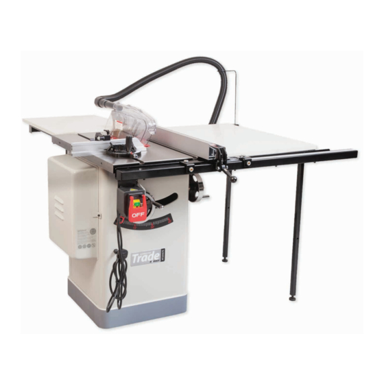
- Page 1 Code 105573 Original Instructions AT254LTS Harvey Table Saw AT&M: 23/03/2020 BOOK REF : 106214 BOOK VERSION: 3...
-
Page 2: Eu Declaration Of Conformity
Model and conforms to the machinery example for which the EC Type-Examination Certificate No BM 50416470 has been issued by Harvey Industries Co., Ltd. Signed at: 01 Building, No.68 Suyuan Road, Jiangning Economic & Technological Development Zone, Nanjing 211100 China (Mainland) Andrew Parkhouse and complies with the relevant essential health and safety requirements. -
Page 3: What's Included
What’s Included Quantity Item Part Model Number AT254LTS Table Saw Main Body Dado Blade Table Insert Crown Guard Flexible Hose Operating Wheels & Star Knobs Hose Support Bracket Push Stick Extension Table Support Legs Spanner Motor Access Door Mitre Fence Assembly Rip-Fence Hex Keys Rip-Fence Rail... - Page 4 What’s Included...
-
Page 5: Optional Accessories
Optional Accessories ST-1400 Sliding Table Code 104505 The ST-1400 Sliding Table upgrades the AT254TS table saw to have the capacity of a small panel saw. It easily installs onto the AT254TS , but can also be fitted to almost any table saw with a flat front vertical face around 50mm deep and at least 1m in length. -
Page 6: General Instructions For 230V Machines
General Instructions for 230V Machines The following will enable you to observe good working • Carry out a final check e.g. check the cutting tool practices, keep yourself and fellow workers safe and maintain is securely tightened in the machine and the correct your tools and equipment in good working order. -
Page 7: Specification
Specific Safety Precautions Do not attempt to carry out cross cutting operations Remember the emphasis of the ‘push’ should be between the ‘freehand’ , always use the mitre fence for small material and blade and the fence and close to the fence. Use your free hand the sliding carriage for larger workpieces. - Page 8 Assembly/Setup Secure door in place Long caphead bolts washers nuts Screw on the star locking knob...
- Page 9 Assembly/Setup Continues over...
- Page 10 Assembly/Setup Line up the holes & secure Countersink hole...
- Page 11 Assembly/Setup Hex screw Remove the insert plate Raise the blade asssembly to its highest point Press down to lock the spindle Spindle lock button Remove locking nut & saw plate flange using the spanner (E) Wipe over the spindle thread, nut and flange Continues over...
- Page 12 Assembly/Setup Teeth forward Slide on the blade (L) so its up against the rear flange Adjust the four screws to level the insert plate with the table Plate flange Lower the fence (R) down over the fence rail (S). Nut recess Replace the washer and nut, making sure the plate flange slots over the nut’s recess.
- Page 13 Assembly/Setup Hex key (G) Hex screw locking wheel Press down the locking lever Rip-fence Postion the fence against the blade and lock in place. Gap between the blade & fence The rip fence should be level across the width of the table.
- Page 14 Assembly/Setup Riving knife locking pin latch Locked Twist to unlock Clamping plate slot Preset hole Locate the crown guard (B) assembly. Unlock the locking pin latch and insert the riving knife plate down between the clamping plate slot. Rotate the locking pin to the right to engage the pin into the preset hole in the riving knife thus locking the crown guard in position.
- Page 15 Assembly/Setup Scale marker Lock nut Mark the postion of the tape Remove the fence assembly and place to one side. Peel off the backing from the tape (Y) and carefully press down using a cloth onto the rip-fence rail (S). Make sure there are no ripples along the length of the tape.
- Page 16 Assembly/Setup Grub screw to adjust the centre slot Using the supplied Hex key (G) adjust the two grub screws in the mitre fence bar. This reconfigures the centre slot to keep the bar snug in the ‘T’ slot allowing the fence to run true without any side-play.
-
Page 17: Illustration & Parts Description
Assembly/Setup Locking pin Line up the two holes in the control box mounting bracket with Secure in place with the caphead screws and washers. Insert the pre-machined holes to the underside of fence rail mounting the locking pin through the start up button to prevent the plate. - Page 18 Illustration & Parts Description Fence clamping knobs Crown guard Mitre fence Side extension table Access panel 100mm Dust extraction port Control box with emergency stop Saw tilt scale Main saw body lever Adjustable foot Mitre fence distance stop (A), Mitre fence locking handle (B), Mitre fence scale (E) and pointer Mitre locking knob (C) and preset locking pin (D) with adjustable Hex screw (F)
- Page 19 Illustration & Parts Description Flexible hose Hose support bracket Rear table Rip-fence Fence rail Fence clamping lever Extension table Saw tilt support legs operating wheel Motor access door Scale pointer adjusting Hex scew Rise & fall operating wheel and locking knob (G), Saw tilting scale (H) 254mm Saw blade (J), and Saw tilt operating handle &...
- Page 20 Illustration & Parts Description Rip-fence in the upright position for guiding timber through Rip-fence in the down position for guiding narrower timber through Tensioning bolt (A) for drive belt, Saw blade drive belt (B), Saw tilt mechanism (C), Spindle lock button (D), Motor pivot lock (E) Grub screw 90˚...
- Page 21 Setting Up the Saw Blade Setting the Riving Knife DISCONNECT THE MACHINE FROM THE The riving knife should be aligned with the saw blade. To MAINS SUPPLY BEFORE CONTINUING! adjust insert the riving knife (J) as shown on page 14. Adjust the four grub screws to the opposite side of the clamping plate assembly to align the riving knife with the blade, see fig 3-4-5.
- Page 22 Optional Accesories Assembly DISCONNECT THE MACHINE FROM THE MAINS SUPPLY BEFORE CONTINUING! Code 104505 ST-1400 Sliding Table Mounting holes Mounting holes Remove Insert ‘T’ bolt into the ‘T’ slot in the sliding table (a) Adjust the three caphead screws until the slide table carriage is slightly proud (0.5-1mm) with the main saw table (A).
- Page 23 Optional Accesories Assembly Secure the table in place Locked Un-locked The sliding table locking pin knob is spring loaded. Pull and twist to engage or disengage the locking pin. UJK STF-1400 Telescopic Mitre Fence Arm ‘T’ Bolt Lock nut Locate the two support legs (b). Insert the ‘T’ bolt into the machine slot to each end of the sliding table (a).
- Page 24 Optional Accesories Assembly Remove Hex screw and rotate the scale indicator out of the way to install the mitre fence (f). Slot pre-drilled hole in the fence down over the threaded pin on the mounting bar (g) and lower in place . 24 24...
- Page 25 Optional Accesories Assembly Square Place a square against the blade/fence and check the pointer on the scale is at ‘ZERO’ . If adjustment is required loosen the two caphead scews (a) and reposition until correct. Re-tighten the screws. Clamping wheel Scale Undo the mitre fence scale clamping wheel, using a steel rule measure 100mm back from the saw tip, so the scale on the rule...
- Page 26 Optional Accesories Assembly Fence arm scale pointer Clamp Flip stop Locking knobs Telescopic fence arm Pointer Scale Locking pin AT254LTS Table Saw fitted with: • ST-1400 Sliding Table • UJK STF-1400 Mitre Fence with telescopic fence arm, flip stop for repeat cuts and angles from -50° to +50° 26 26...
- Page 27 Optional Accesories Assembly DISCONNECT THE MACHINE FROM THE MAINS SUPPLY BEFORE CONTINUING! Code 104504 Shark S-12 Overhead Crown Guard The Shark S-12 Overhead Crown Guard is for the AT254TS or AT254LTS Table Saw. This style of crown guard offers a higher level of user safety and a more efficient dust collection.
- Page 28 Optional Accesories Assembly Mounting flange 5. Install the stand pole unit to the support arm by four 8. Line up the threaded square bolt (A) with the mounting M10x40mm Hex screws and tighten securely, see diagram 5. flange on the guard unit and secure it to the arm. Fit a retaining clip over the flexible soft pipe and secure it in place onto the overhead guard assembly outlet (B), see diagram 8-9.
- Page 29 Optional Accesories Assembly Overhead Guard Assembly Square bolt The overhead crown guard needs to be adjusted to the blade. 9. The crown guard must have 15mm clearance between the blade and the side of the guard, see diagram 10, fig 2. To adjust release the two Hex bolts holding the arm unit bracket assembly, see diagram 11.
- Page 30 Optional Accesories Assembly Stop Cam wheel To adjust, release the locking clamp (G) to the base of stand pole unit, using the supplied Hex key rotate the cam wheel stop. Swing the arm assembly until the cam wheel is up against the stop, make further adjustment if required and tighten the clamp (G) when finished, diagram 17-18-19-20.
- Page 31 Optional Accesories Assembly Code 104503 Dado Blade Set This 204mm diameter Dado Blade Set comprises 2 x 24 tooth TCT outer blades, 6 inner chipper blades and 4 spacers. The chippers and spacers fit between the outer TCT blades. Simply select the inner chippers and spacers required to cut the width of slot required.
- Page 32 Optional Accesories Assembly Wrong! DO NOT OVERLAP the blade teeth. Use the supplied spacers between the blades to make small adjustments in the height. Outer TCT blade Correct! The teeth equally spaced and pointing forward. Wrong! Place the outer TCT blade on top and check the tooth is the same height as the timber.
- Page 33 Optional Accesories Assembly Inner TCT blade Spacer Turn the ‘Dado’ blade assembly over so the inner TCT blade is on top in preparation for installation. Plate flange Outer plate flange/nut Clean the inner and outer plate flanges Make sure the plate flange slots over the nut’s recess. Teeth forward Slide the inner TCT blade over the shaft and up against the inner plate flange.
- Page 34 Operating Instructions CLEAR ALL THE TOOLS AWAY FROM Locking knob WORK AREA! CONNECT THE MACHINE TO THE MAINS SUPPLY! Connect the machine to the mains supply. Remove the locking pin from the power switch, see fig 01, give the machine a test run, by pressing the On/Off buttons.
- Page 35 Operating Instructions 3-5mm above workpiece 9. The riving knife acting as a back guard that stops the wood from closing up onto the blade and being ejected. The riving DURING OPERATION IF YOU NOTICE A BUILD knife must be thicker than the plate of the saw blade but less UP OF SAW DUST STOP THE MACHINE AND than the kerf (this is the thickness of cut).
-
Page 36: Changing The Saw Blade
Operating Instructions Rip Saw Cutting HSE Health and Safety Executive A push stick must be used when making cuts less than 300mm To operate the panel saw correctly, it is recommended to in length. The push stick should be at least 450mm long with visit the HSE (Health and Safety Executive) website at a ‘bird’s mouth to one end. - Page 37 Changing the Saw Blade Teeth forward Slide on the blade (L) so it’s up against the rear flange 2. Remove the nut/plate flange and place safely aside. Lift out the blade (L), check for signs of damage such as missing teeth. If the blade is still usable store safely away.
-
Page 38: Maintenance
Maintenance DISCONNECT THE MACHINE FROM THE MAINS SUPPLY BEFORE CONTINUING! Belt Tension After a period of time if you notice the blade stopping in mid cut and the motor still spinning, the V- belt will need tension- ing. Lower the blade completely and tilt the assembly over to 45˚... -
Page 39: Troubleshooting Guide
Troubleshooting Guide PROBLEM PROBABLE CAUSE SOLUTION Saw will not start Saw not plugged in. Plug in saw. Fuse blown or circuit breaker tripped. Replace fuse or reset circuit breaker. Cord damaged. Have cord replaced by a certified electrician. Overload kicks Extension cord too light or too long. - Page 40 Exploded Diagrams/Lists Table Saw Body PART DESCRIPTION Button Head Screw M5 x 12 STD Table Insert Plate Flat Head Screw M5 x 10 Button Head Screw M5 x 16 Flat Head Screw M5 x 20 Hex Nut 8mm Main Table Angle Scale Motor Cover Lock Nut 3mm...
- Page 41 Exploded Diagrams/Lists Trunnion Assembly Continues over...
- Page 42 Exploded Diagrams/Lists PART DESCRIPTION Arbor Flange Lock Nut M16 Arbor Nut Flat Washer 16mm Knurled Knob Cap Screw M8x 20 Splitter Adjust Block Lock Washer 8mm Spring Flat Washer(W) 8mm Spacer Motor Locking Pin Cap Screw M6 x 16 Splitter Tighten Clip Lock Washer 6mm Cap Screw M6 x 25 Flat Washer 6mm...
- Page 43 Exploded Diagrams/Lists Control Box PART DESCRIPTION Lock Washer 4mm Tap Screw M3.5 x 19 Flat Washer 4m Power Switch KEDU KJD17B 230V Clamp-On Terminal Ring 222-1 Paddle Switch Lockout Pin Switch Bracket Switch Box Tap Screw M3.5 x 10 Circuit Breaker 16A 220V Strain Relief TYPE-3 M18-1.5 Circuit Breaker Nut M10-1.5 Power Cord 14G 3W 72”...
- Page 44 Exploded Diagrams/Lists Crown Guard PART DESCRIPTION Splitter Flat Head Screw M4 x 10 Shoulder Screw M6.5 x 25 Guard Support 1 Shoulder Screw M6.5 x 10 Guard Support 2 Right Guard Stepped Nut M4 Tap Screw M2.9 x9.5 Vacuum Cleaner Riving Knife Left Guard Hose Sup port Arm...
- Page 45 Exploded Diagrams/Lists Mitre Guage PART DESCRIPTION Lock Washer 4mm 401A Miter Gauge Assembly Button Head Screw M4 x 6 Guide Bar Miter Knob Angle Scale Flat Washer 4mm Rivet Crosscut Fence Set Screw M8 x 6 Square Nut M6 Miter Ring Flat Washer 6mm Flat Head Screw M5 x 8 Lock Washer 6mm...
- Page 46 Exploded Diagrams/Lists Rip-Fence PART DESCRIPTION Fence Lock Knob Glide Pad Lock Nut 10mm Button Head Screw M5 x 8 Hex Nut 12mm Flat Washer 5mm Set Screw M12 x 15 Ruler X-Ray Film Set Screw M12 x 10 Fence Insert Hex Bolt M6 x 40 Set Screw M 12 x 30 Cam Plate...
- Page 47 Exploded Diagrams/Lists Side/Rear Extension Table PART DESCRIPTION Lock Washer 8mm End Cap Hex Nut 8mm Guide Tube Rear Rail Front Rail Cap Screw M10 x 25 Scale Flat Washer 10mm Flat Washer 6mm Cap Screw M8 x 35 Lock Washer 6mm Cap Screw M6 x 16 Extension Board Flat Head Screw M8 x 35...
- Page 48 Exploded Diagrams/Lists Optional ST-1400 Sliding Table Code 104505 PART DESCRIPTION Lock Lever M8-1.25 Button HD Screw M6-1 x 12 Support Leg Lock Washer 6MM Hex Nut M8-1.25 Flat Washer 6MM Foot Pad Sliding Table Side Cover Lock Lever Flat Washer 8MM Sliding Table Assembly Stop Plate Cap Screw M8-1.25 x 25...
- Page 49 Exploded Diagrams/Lists Optional UJK STF-1400 Telescopic Mitre Fence Arm PART DESCRIPTION Flat Washer 6MM Knurled Handle M8-1.25 Cap Screw M6-1 x 16 Long Crosscut Fence Set Screw M6-1 x 8 Knob Bolt M6-1 x 35 Flip Stop Bracket Handle Screw M6-1 x 8 Flip Stop Pivot Pin Square Nut M5-.8 Flip Stop...
- Page 50 Exploded Diagrams/Lists Optional Shark S-12 Overhead Crown Guard Code 104504...
- Page 51 Exploded Diagrams/Lists PART DERIPTION Lock Bolt Cap Screw M10 x 25 Connection Block B Spring Washer 10 Connection Block A Flat Washer 10 Cap screw M8 x 25 Support Arm Spring Washer 8 Foot Flat Washer 8 Nut 8 Cap Screw M5 x 16 Foot Bracket Spring Washer 5 Fixed Plate...
-
Page 52: Wiring Diagram
Wiring Diagram... - Page 53 Notes...
- Page 54 Notes...
- Page 55 Notes...
- Page 56 The Axminster guarantee is available on Craft, Trade, Engineer, Air Tools & CNC Technology Series machines Buy with confidence from Axminster! So sure are we of the quality, we cover all parts and labour free of charge for three years! For more information visit axminster.co.uk/3years The packaging is suitable for recycling.
Need help?
Do you have a question about the Axminster AT254LTS and is the answer not in the manual?
Questions and answers