Advertisement
Quick Links
Advertisement

Subscribe to Our Youtube Channel
Related Manuals for Robe ANOLIS Eminere Inground 2


Summary of Contents for Robe ANOLIS Eminere Inground 2
- Page 1 Version 1.1...
-
Page 2: Table Of Contents
Eminere Inground Table of contents 1. Safety instructions ..............................3 2. Fixture exterior view ..............................4 3. Installation .................................. 4 3.1 Mounting the Eminere Inground .......................... 5 4. Technical specifications ............................12 5. Cleaning and maintenance ............................15 5.1 Disposing of the product ............................ 15 6. -
Page 3: Safety Instructions
Eminere Inground FOR YOUR OWN SAFETY, PLEASE READ THIS USER MANUAL CAREFULLY BEFORE POWERING OR INSTALLING YOUR Eminere ! Save it for future reference. This device has left our premises in absolutely perfect condition. In order to maintain this condition and to ensure safe operation, it is absolutely necessary for the user to follow the safety instructions and warnings written in this manual. -
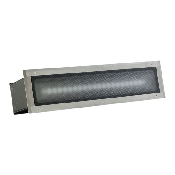
Page 4: Fixture Exterior View
Eminere Inground Immunity of the equipment is designed for electromagnetic environments E1, E2, E3 according to the standard EN55103-2 ed.2 Electromagnetic compatibility. Product family standard for audio, video, audiovisual and entertainment lighting control apparatus for professional use. Part 2: Immunity. The installation company should check levels of possible interferences above the tested levels E1,E2,E3 given by this standard (e.g. -
Page 5: Mounting The Eminere Inground
Eminere Inground 3.1 Mounting the Eminere Inground Warning! If the Eminere Inground will be exposed to max. allowed static load, the subsoil under the installation sleeve has withstand load of 35kN. Example of installation of the Eminere Inground 2 1. Prepare an adequate hole with a good drainage leaving at least 300 mm of gravel on the bottom of the hole for inserting the mounting sleeve (1) into the prepared hole. - Page 6 Eminere Inground Note: the cabel (11) of the Eminere Inground is 2 m long, we recommend to shorten the cable on 1 m. The supply/data cable to and from the mounting sleeve must be placed in a protective tube (12). 6.
- Page 7 Eminere Inground 2. Connect cables to the junction box (20). Wiring of the Eminere cable (CE version): Core Power Connection Core DATA Connection Brown Purple Data + Blue Orange Data - Yellow/Green Shielding Data ground (0V) (earth) Wiring of the Eminere cable (US version): Core Power Connection Core...
- Page 8 Eminere Inground We recommend to apply an adequate layer of the paste LOCTITE 5331 on the plastic holder of the cable gland before inserting it into the body of the gland and an adequate layer of the paste LOCTITE 577 on the thread of the gland body.
- Page 9 Eminere Inground 4. Screw the cover (18) with gasket (19) to the junction box by means of the four screws (17) and check they are fully tighten. 8. If you install two or more Emineres Inground side by side, you have to screw three types of the cover plates: end (15), middle (23) and continuous (22).
- Page 10 Important: the item “E-box mode“ has to be set at “Pass-Thr“ (Personality E-box mode Pass-Thr) in the E- box menu. DMX addressing of connected Emineres Inground has to be done manually by means of the Robe Universal Interface (or its wireless version Robe Universal Interface WTX) and a software RDM Manager. See the E-box user manual.
- Page 11 Eminere Inground Eminere Inground 4 Voltage Cable length * 120V 190V 230V 277V 10 m 20 m 30 m 50 m 70 m 100 m Cable length is a total cable length between E-box and last connected Eminere. Example of connection: E-box Daisy Total cable length= L1+∑L2+∑L3.
-
Page 12: Technical Specifications
Eminere Inground 4. Technical specifications Power supply • Electronic auto-ranging • Input voltage: 120 - 277V AC, 50-60 Hz • Power consumption: Eminere Inground 2: 45W Eminere Inground 4: 85W • Inrush current: Eminere Inground 2: <70A/250µs Eminere Inground 4: <100A/200µs Optic •... - Page 13 Eminere Inground • E-box Lite 1 output 1 Main power Input Control: DMX, W-DMX control, RDM Pixel control (1px= 1ft) 120-277V Input Connection via screw terminal blocks, inlets via grommet IP67 Mounting method • Inground mount Adjustability • +/- 15° after instalation Housing •...
- Page 14 Eminere Inground Dimensions (All dimensions in mm [inch]) • Eminere Inground 2/Eminere Inground 4 Dimensions with mounting sleeve (All dimensions in mm [inch]) • Eminere Inground 2/Eminere Inground 4...
-
Page 15: Cleaning And Maintenance
Description of changes the manual 09/07/2020 Voltage range change Specifications are subject to change without notice. July 9, 2020 Copyright © 2019-2020 Robe Lighting - All rights reserved Made in CZECH REPUBLIC by ROBE LIGHTING s.r.o. Palackeho 416/20 CZ 75701 Valasske Mezirici...
Need help?
Do you have a question about the ANOLIS Eminere Inground 2 and is the answer not in the manual?
Questions and answers