Table of Contents
Advertisement
Quick Links
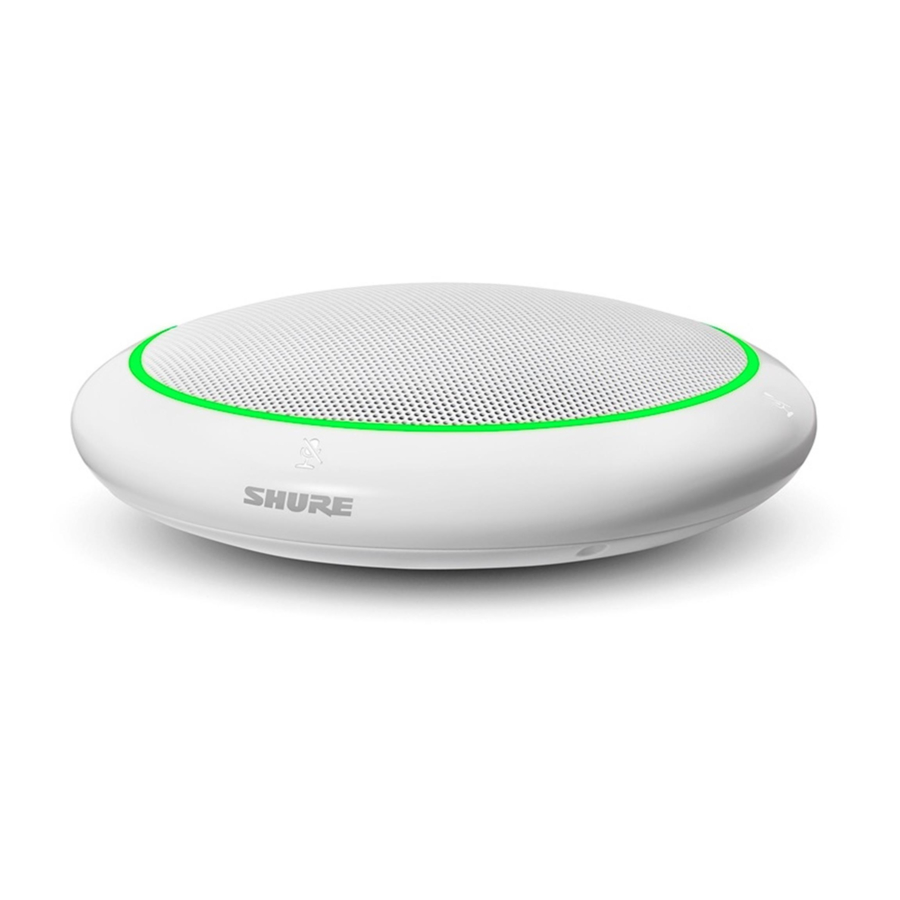
MXA310 -- Table Array Microphone
Overview
General Description
®
The Microflex Advance™ table array is a premium networked tabletop microphone for AV conferencing environ
ments, including boardrooms, huddle rooms, and multi-purpose spaces. Revolutionary technology from the Shure
DSP suite includes Steerable Coverage™, with selectable polar patterns on 4 independent channels to capture
participant audio. The innovative new toroid polar pattern delivers 360° coverage, while rejecting sound from di
rectly above the microphone. Browser-based control software provides an intuitive user interface for microphone
attributes, including channel configuration, automatic mix settings, and preset templates. The microphone inte
grates seamlessly with Dante™ digital networked audio and thirdparty preset controllers, including Crestron and
AMX, to deliver a high-quality AV conferencing experience that appeals equally to integrators, consultants, and
meeting participants.
Features
Configurable Coverage
• Steerable Coverage delivers precise pick-up for up to 4 independent lobes
• Shure DSP Suite provides fast-acting automatic mixing and channel equalization
• Innovative toroid polar pattern delivers 360° coverage, while rejecting sound from directly above the microphone
to reduce noise caused by HVAC systems or video projectors.
Software Control
• Intuitive software interface provides comprehensive microphone and pattern control
• Includes templates to speed initial setup and 10 customizable presets to import or export configurations be
tween multiple microphones
Network Connectivity
• Four discrete audio channels and an additional automix channel are delivered over a single network cable
• Dante™ digital audio coexists safely on the same network as IT and control data, or can be configured to use a
dedicated network
• Control strings available for third-party preset controllers including Crestron and AMX
Professional Design
• Sleek, low-profile industrial design blends with contemporary board rooms and meeting spaces
1/76
Advertisement
Table of Contents

Subscribe to Our Youtube Channel
Related Manuals for Shure MXA310


Summary of Contents for Shure MXA310
- Page 1 The Microflex Advance™ table array is a premium networked tabletop microphone for AV conferencing environ ments, including boardrooms, huddle rooms, and multi-purpose spaces. Revolutionary technology from the Shure DSP suite includes Steerable Coverage™, with selectable polar patterns on 4 independent channels to capture participant audio.
-
Page 2: System Overview
② Analog audio (microphone to network) Analog equipment, such as a wireless microphone system or a gooseneck microphone on a podium, connects to the Dante™ audio network through a Shure Network Interface (model ANI4IN) for a completely networked confer encing system. -
Page 3: System Planning And Gear Requirements
Analog microphones connect to the network through the Shure ANI4IN, while loudspeakers con nect through the Shure ANI4OUT. - Page 4 Expanded Control for Analog Devices Analog devices that are connected to the network through a Shure network interface (ANI4IN/ANI4OUT) benefit from additional remote control: Volume levels, equalization, and signal routing are managed through the web appli cation. For example, adjusting loudspeaker volume or muting a wired microphone, which would normally be done from the hardware, can now be controlled remotely over the network.
- Page 5 Network Switch The network switch provides central connectivity for all networked components. Audio from any networked Shure microphones that are connected to the switch can be routed to any Dante-enabled device. The switch sends and receives audio and control data,...
- Page 6 Shure ANI4IN Audio Network Interface (Analog-to-Dante Converter) The Shure ANI4IN Audio Network Interface converts 4 channels of analog audio into independent digital au dio channels on a Dante network. Adjustable gain and +48V phantom power deliver the flexibility to support line, auxiliary, and microphonelevel devices.
- Page 7 ANI4IN Audio Network Interface re ceives analog logic signals and con verts them into Ethernet control strings. System Use Cases These use cases will help you understand how Shure devices fit in conference rooms, huddle rooms, and multi purpose spaces. 7/76...
- Page 8 • Required devices Power Over Ethernet and Hardware Requirements All Shure devices included in these use cases require Power over Ethernet (PoE, class 0). Refer to the Dante and Networking section for additional information on cable and network switch requirements.
- Page 9 Connect a computer to the ANI on port 2 or 3 with a network cable to provide control of the array microphone and other networked components. ③ Shure ANI analog outputs to audio processor Step 1: Route signals with Dante Controller software Route the channels from the microphone (Dante transmitter) to the MXWANI channels (Dante receiver).
- Page 10 Shure Incorporated Telephone Conference with Dante-enabled Audio Processor ① Array microphone to network switch Connect the microphone output with a network cable to any port on the switch that supplies Power over Ethernet (PoE). ② Computer to network switch Connect a computer to the network switch to provide control of the microphone and other networked components.
- Page 11 Telephone Conference with Breakout Boxes and Audio Processor In this scenario, two MXA310 microphones are used for a total of 8 Dante audio channels. Using two network in terfaces, the Dante channels are converted to analog signals for acoustic echo cancellation.
- Page 12 Shure Incorporated ① Microphone to network switch Connect the array microphone output with a network cable to any port on the switch that supplies power over eth ernet (PoE). ② Computer to network switch Connect a computer to the network switch to provide control of the microphone and other networked components through the software control panel.
- Page 13 Shure Incorporated From the network switch: Use network cables to connect each ANI4OUT to the network switch. A single ANI4OUT receives 4 channels of Dante audio, and converts them to 4 analog signals, delivered through XLR out puts or block connectors. Using two of them, all 8 channels from the microphones can be connected to analog in...
- Page 14 Shure Incorporated Web Conferencing Software with Dante Virtual Soundcard ① Microphone to network switch Connect the microphone output with a network cable to any port on the switch that supplies Power over Ethernet (PoE). ② Computer to network switch 14/76...
- Page 15 Shure Incorporated Connect a computer to the network switch to provide control of the microphone and other networked components through the software control panel. The computer also runs Dante Virtual Soundcard, Dante Controller, and the web conferencing software. • Dante Virtual Soundcard / Controller: Turn on the Dante Virtual Soundcard and use the controller software to route the microphone signal to the computer.
-
Page 16: Video Conference
Shure Incorporated Video Conference ① Microphone to network switch Connect the microphone output with a network cable to any port on the switch that supplies power over Ethernet (PoE). ② Computer to network switch Connect a computer to the network switch to provide control of the microphone and other networked components through the software control panel. -
Page 17: Hardware And Installation
Shure Incorporated ③ ANI4OUT (digital-to-analog conversion) Each ANI4OUT receives 4 channels of Dante audio, and converts them to 4 analog signals, delivered through XLR outputs or block connectors. Input: Connect the ANI4OUT to the network switch with a network cable Ouput: Connect the analog output to the audio input on the video codec ④... -
Page 18: Led Light Ring
Shure Incorporated On = network link established Flashing = network link active ⑤ Network Speed LED (Amber) Off = 10/100 Mbps On = 1 Gbps ⑥ Reset Button Use a paperclip or similar tool to push the reset button. ⑦ Mute Buttons Four touch-sensitive buttons control the mute status for each channel. - Page 19 Shure Incorporated Microphone Status LED Behavior / Color Reset Network reset: Green (slow flashing) Factory reset: Green (fast flashing) Error Red (split, alternate flashing) Device power-up Blue (rotates around ring) Installing the Cable-Exit Plug The plug covers the cable exit for permanent installations in which the cable is routed down through a table.
- Page 20 Shure Incorporated 3. Align the tube into the recessed area in the center of the microphone. Install the 3 screws (removed in step 1) to secure the tube. 4. Slide one of the rubber washers to the base of the tube.
-
Page 21: Power Over Ethernet (Poe)
Shure Incorporated 6. Guide the cable through the hole in the table. Then, place the tube through the hole in the table and gently press the microphone down. 7. Attach the remaining rubber washer and wing nut from underneath the table. Then, tighten the wing nut to se... -
Page 22: Microphone Placement
Shure Incorporated Power over Ethernet is delivered in one of the following ways: • A network switch that provides PoE • A PoE injector device Microphone Placement Microphone Placement Each microphone has 4 channels that can be aimed independently, based on the seating arrangement. Each channel features independent polar patterns and additional channel settings, accessible through the web applica... - Page 23 Shure Incorporated Toroid Pattern Applications The toroid pattern rejects sound from directly above the microphone to reduce noise from video projectors or other sources of unwanted sound. It is the simplest way to ensure equal coverage among all talkers, while retaining the benefits of the rejection provided by a directional polar pattern.
- Page 24 Shure Incorporated Noise from a ceiling-mounted projector is rejected, while all talkers are covered. For a table with a single microphone and more than 4 talkers, the toroid pattern to ensures that all voices are heard equally. 24/76...
-
Page 25: Software Installation, Management, And Security
Software Installation, Management, and Security Accessing the Web Application The Shure Web Server Discovery application finds all Shure devices on the network that feature a web-based GUI. Follow these steps to install the software and access the web application: ① Install the Shure Discovery application... -
Page 26: Web Application Browser Compatibility
Firmware is embedded software in each component that controls functionality. Periodically, new versions of firmware are developed to incorporate additional features and enhancements. To take advantage of design im provements, new versions of the firmware can be uploaded and installed using the Shure Update Utility. Software is available for download from http://www.shure.com. -
Page 27: Microphone Configuration
Settings About The format for Shure device’s firmware is MAJOR.MINOR.PATCH. (Ex. 1.6.2 where 1 is the Major firmware level, 6 is the Minor firmware level, and 2 is the Patch firmware level.) At minimum, devices that operate on the same subnet should have identical MAJOR and MINOR release numbers. - Page 28 Shure Incorporated Microphone Configuration The microphone features multiple configurations to adapt to any meeting space, based on these variables: • Table size and shape • Number of meeting participants • Participant seating arrangement Selecting Pickup Patterns 1. Select Configuration > Coverage 2.
-
Page 29: Adding Or Removing A Channel
Shure Incorporated Pickup Pat tern Directional Characteristic Use When Each pickup area features indepen Maximum noise rejection and channel separation dent polar pattern control. Select each are desired, and when the seating configuration is polar pattern setting based on the unlikely to change. -
Page 30: Adjusting Levels
Shure Incorporated load preset: Opens a configuration from the device import from file: Downloads a preset file from a computer onto the device. Files may be selected through the browser or dragged into the import window. export to file: Saves a preset file from the device onto a computer Templates Use a template as a starting point when configuring coverage. - Page 31 Shure Incorporated When the microphone is centered on a rectangular table, use the channel gain to balance the levels and compen sate for the unequal distances. 1. Perform a level check for each coverage area, using a typical speech volume. Adjust the faders so the meters are peaking at approximately -20 dBFS.
-
Page 32: Mute And Fader Groups
Shure Incorporated To adjust, go to > . These faders adjust a channel's gain after the lobe has gated on. Configuration Automix Adjusting the gain here will not affect the automixer's gating decision. Only use these faders to adjust the gain of a talker after you are satisfied with the automixer's gating behavior. -
Page 33: Parametric Equalizer (Peq)
Shure Incorporated Mute Behavior LED activity when the microphone is muted Mute Color LED color when the microphone is muted Parametric Equalizer (PEQ) Maximize audio quality by adjusting the frequency response with the parametric equalizer. Common equalizer applications: • Improve speech intelligibility •... - Page 34 Shure Incorporated Copy, Paste, Import, and Export Equalizer Channel Settings These features make it simple to use effective equalizer settings from a previous installation, or simply accelerate configuration time. Copy and Paste Use to quickly apply the same PEQ setting across multiple channels.
-
Page 35: Equalizer Applications
Shure Incorporated When to Use the Channel and Automix Equalizers Apply Automix EQ to make system-wide changes, such as a treble boost to improve speech clarity. Use Channel EQ to make adjustments to a specific channel. For example, to reduce unwanted noise picked up by only one channel. -
Page 36: Automix Settings
Automix Modes Classic Classic mode emulates the Shure SCM820 automixer (in its default settings). It is renowned for fastacting, seam less channel gating and consistent perceived ambient sound levels. Off-attenuation in this mode is fixed at -12 dB per channel, regardless of the number of open channels. -
Page 37: Software Reset Options
There are two reset functions: Network reset (press but Resets all Shure control and audio network IP settings to factory defaults ton for 4-8 seconds) Full factory reset (press Restores all network and web application settings to the factory defaults. -
Page 38: Low-Cut Filter
Shure Incorporated Reboot Device:In the web application (settings > factory reset), there is a Reboot Device button, which simply powercycles the device as if it were unplugged from the network. All settings are retained when the device is re booted. -
Page 39: Using A Third-Party Control System
• Loading presets • Adjusting levels A complete list of command strings is available in the device help or from www.shure.com. To send a logic signal out when the mute button is pressed: 1. In the web application, select Configuration > Button Control. - Page 40 The MXA310 will send a REPORT command when any of these parameters change. The character “x” in all of the following strings represents the channel of the MXA310 and can be ASCII numbers 0 through 5 as in the following table. All channels...
- Page 41 < GET x ALL > through 5. Use this command on first power on to update the status of all parameters. MXA310 Response: The MXA310 responds with individ < REP ... > ual Report strings for all parameters. Get Model Number Command String: <...
- Page 42 MXA310 Response: Where < REP x CHAN_NAME {yyyyyyyyyyyyyyyyyyyyyyyyyyyyyyy} > yyyyyyyyyyyyyyyyyyyyyyyyyyyyyyy is 31 characters of the channel name. The MXA310 always re sponds with a 31 character name. Get Device ID Command String: The Device ID command does not < GET DEVICE_ID >...
- Page 43 < GET x AUDIO_GAIN_HI_RES > through 5. Channel number 0 (all channels) is not valid for this com mand. MXA310 Response: Where yyyy takes on the ASCII val < REP x AUDIO_GAIN_HI_RES yyyy > ues of 0000 to 1400. yyyy is in steps of one-tenth of a dB.
- Page 44 < GET x AUDIO_MUTE > through 5. See table on page 1. Channel Audio Mute is pre-meter. MXA310 Response: The MXA310 will respond with one < REP x AUDIO_MUTE ON > of these strings. < REP x AUDIO_MUTE OFF >...
- Page 45 Shure Incorporated Command String: < SET x AUDIO_MUTE TOGGLE > MXA310 Response: The MXA310 will respond with one < REP x AUDIO_MUTE ON > of these strings. < REP x AUDIO_MUTE OFF > Get Device Audio Mute Command String: Device Audio Mute is equivalent to <...
- Page 46 The microphone will send a REPORT message whenev er the status changes. MXA310 Response: The MXA310 will respond with one < REP x AUDIO_OUT_CLIP_INDICATOR ON > of these strings. < REP x AUDIO_OUT_CLIP_INDICATOR OFF > Flash Lights on Microphone...
- Page 47 Shure Incorporated Stop Metering Command String: A value of 00000 is also acceptable. < SET METER_RATE 0 > MXA310 Response: < REP METER_RATE 00000 > Get Automixer Gain Metering Rate (firmware > v3.0) Command String: < GET METER_RATE_MXR_GAIN > MXA310 Response: Where sssss is the metering rate in <...
- Page 48 < GET PRESET3> MXA310 Response: Whereyyyyyyyyyyyyyyyyyyyyyyyyy < REP PRESET1 {yyyyyyyyyyyyyyyyyyyyyyyyy} > is 25 characters of the preset name. The MXA310 always responds with < REP PRESET2 {yyyyyyyyyyyyyyyyyyyyyyyyy} > a 25 character preset name < REP PRESET3 {yyyyyyyyyyyyyyyyyyyyyyyyy} > Get Gate Out Status...
- Page 49 < GET EXT_SWITCH_OUT_STATE > send this command. The MXA310 will send a REPORT message whenever the status changes. MXA310 Response: < REP EXT_SWITCH_OUT_STATE ON > The MXA310 will respond with one < REP EXT_SWITCH_OUT_STATE OFF > of these strings. Mute Button Status...
- Page 50 “Logic Out” or "Disabled" AND Light Ring “Lighting Style” is set to “Ring” in the GUI. MXA310 Response: The MXA310 will respond with one < REP DEV_LED_IN_STATE ON > of these strings. < REP DEV_LED_IN_STATE OFF >...
- Page 51 Where x is ASCII channel number: 1 < SET x CHAN_LED_IN_STATE ON > through 4. Send one of these com mands to the MXA310. This com < SET x CHAN_LED_IN_STATE OFF > mand is only available when both “Mute Control Function” is set to “Logic Out”...
- Page 52 0 = LED disabled 1 = 20% 2 = 40% 3 = 60% 4 = 80% 5 = 100% MXA310 Response: < REP LED_BRIGHTNESS n > Get LED Mute Color Command String: < GET LED_COLOR_MUTED > MXA310 Response: Where nnnn can be RED, GREEN, <...
- Page 53 RED, GREEN, BLUE, PINK, PURPLE, YELLOW, ORANGE, WHITE, GOLD, YELLOWGREEN, TURQUOISE, POWDERBLUE, CYAN, SKYBLUE, LIGHTPURPLE, VIOLET, or ORCHID. MXA310 Response: < REP LED_COLOR_MUTED nnnn > Get LED Unmute Color Command String: < GET LED_COLOR_UNMUTED > MXA310 Response: Where nnnn can be RED, GREEN, <...
- Page 54 Where nnn can be ON, OFF, or < SET LED_STATE_UNMUTED nnn > FLASHING. MXA310 Response: < REP LED_STATE_UNMUTED nnn > Reboot MXA310 (firmware > v2.0) Command String: < SET REBOOT > MXA310 Response: The MXA310 does not send a re sponse for this command 54/76...
- Page 55 Get Low Cut Filter (firmware > v2.0) Command String: < GET LOW_CUT_FILTER > MXA310 Response: The MXA310 will respond with one < REP LOW_CUT_FILTER ON > of these strings. < REP LOW_CUT_FILTER OFF > Set Low Cut Filter (firmware > v2.0)
- Page 56 < SET xx PEQ yy ON > MXA915. < SET xx PEQ yy OFF > MXA310 Response: Where xx is the PEQ block 01-04. 5 < REP xx PEQ yy ON > is the PEQ on the automix out chan...
- Page 57 Shure Incorporated MXA310 Response: The MXA310 will respond with one < REP x POLAR_PATTERN TOROID > of these strings. < REP x POLAR_PATTERN OMNI > < REP x POLAR_PATTERN CARDIOID > < REP x POLAR_PATTERN SUPER > < REP x POLAR_PATTERN HYPER >...
- Page 58 Increment/Decrement Lobe Angle (firmware > v2.0) Command String: Send one of these strings to the < SET x LOBE_ANGLE INC nn > MXA310. Where nn is 15, 30, 45, 60, etc. < SET x LOBE_ANGLE DEC nnn > MXA310 Response: Where nnn is 015, 030, 045, 060, <...
- Page 59 Get Network Audio Channel Name Command String: Where xx is channel number All < GET xx NA_CHAN_NAME > channels: 0 MXA310: 1-5, 5 being automix channel MXA310 Response: Where xx is channel number. Where < REP xx NA_CHAN_NAME {yyyyyyyyyyyyyyyyyyyyyyyyyyyyyyy} {yyyyyyyyyyyyyyyyyyyyyyyyyyyyyyy} is 31 char channel name.
- Page 60 Shure Incorporated Get Control Network MAC Address Command String: < GET CONTROL_MAC_ADDR > MXA310 Response: Where yy:yy:yy:yy:yy:yy is a 17 char < REP CONTROL_ MAC_ADDR yy:yy:yy:yy:yy:yy > literal string formatted as 6 octets, each separated by a colon. Exam ple: 00:0E:DD:FF:F1:63 Restore Default Settings (firmware >...
- Page 61 < GET NUM_ACTIVE_MICS > MXA310 Response: where n is number of active chan < REP NUM_ACTIVE_MICS x > nels that takes on values: MXA310: channels 1-4 Get Automix Channel Solo Enable Command String: where x is channel number: 0 is not <...
-
Page 62: Networking And Dante
Shure Incorporated Networking and Dante Digital Audio Networking Dante digital audio is carried over standard Ethernet and operates using standard Internet Protocols. Dante pro vides low latency, tight clock synchronization, and high Quality-of-Service (QoS) to provide reliable audio transport to a variety of Dante devices. Dante audio can coexist safely on the same network as IT and control data, or can be configured to use a dedicated network. -
Page 63: Networking Terminology
• Always use a "star" network topology by connecting each component directly to the switch or router. • Connect all Shure networked devices to the same network and set to the same subnet. This applies to all de vices that audio signals must be routed between (managed through Dante Controller). It is also required in or... -
Page 64: Mac Address
Shure Incorporated This network carries both the Dante digital audio and the control data for Dante Controller. The network audio re quires a wired, gigabit Ethernet connection to operate. Device IP Settings Configure IP Sets IP mode of the selected network interface: •... -
Page 65: Packet Bridge
Note: The maximum accepted payload 140 bytes. Any content is allowed. 2. The Shure device will send a response packet over unicast UDP to the controller, using a destination UDP port identical to the source port of the query packet. The payload of the response packet follows this format:... - Page 66 MAC address, as array of 6 bytes Note: The Shure device should respond in less than one second on a typical network. If there is no response, try sending the query again after verifying the destination IP address and port number.
-
Page 67: Important Product Information
EMC conformance to Environment E2: Commercial and Light Industrial. Testing is based on the use of supplied and recommended cable types. The use of other than shielded (screened) cable types may degrade EMC perfor mance. Changes or modifications not expressly approved by Shure Incorporated could void your authority to operate this equipment. 67/76... -
Page 68: Information To The User
This product meets the Essential Requirements of all relevant European directives and is eligible for CE marking. The CE Declaration of Conformity can be obtained from Shure Incorporated or any of its European representa tives. For contact information please visit www.shure.com... -
Page 69: Specifications
Shure Incorporated Cable-exit plug (silver) 65C29429 Mounting tube wing nut 65A27351 Mounting tube 31A2165 Rubber Isolation Ring 66A405 Nylon cable ties (4) 80A583 Flush mounting tray kit (aluminum) A310AL-FM Flush mounting tray kit (black) A310B-FM Specifications All specifications measured from cardioid polar pattern. Values for all patterns are within ± 3 dB of these specifica... - Page 70 Shure Incorporated Storage Temperature Range −29°C (20°F) to 74°C (165°F) Audio Frequency Response 100 to 20,000 Hz Dante Digital Output Channel Count 5 total channels (4 independent transmit channels, 1 Automatic mixing transmit channel) Sampling Rate 48 kHz Bit Depth...
-
Page 71: Frequency Response
Shure Incorporated Dynamic Range -15 dB Gain Setting Cardioid 96 dB Toroid 90 dB SPL Built-in Digital Signal Processing Per Channel Equalizer (4-band Parametric) , Mute, Gain (140 dB range) System Automatic mixing, Low-Cut Filter (-12 dB/octave @150 Hz) Assignable to one channel at a time... - Page 72 Shure Incorporated Hypercardioid 72/76...
- Page 73 Shure Incorporated Supercardioid Toroid 73/76...
- Page 74 Shure Incorporated Omnidirectional 74/76...
- Page 75 Shure Incorporated Cardioid 75/76...
- Page 76 Shure Incorporated Bidirectional 76/76...
Need help?
Do you have a question about the MXA310 and is the answer not in the manual?
Questions and answers