Table of Contents
Advertisement
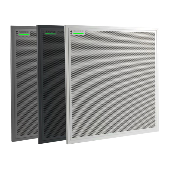
MXA910 -- Ceiling Array Microphone
Overview
General Description
®
The Microflex Advance™ Ceiling Array is a premium networked array microphone for AV conferencing environ
ments, including boardrooms, huddle rooms, and multi-purpose spaces. Revolutionary technology from the Shure
DSP suite includes Steerable Coverage™, with 8 highly directional pickup lobes that capture participant audio
from overhead. Control the microphone with Shure Designer software, or a browser-based web application. The
microphone integrates seamlessly with Dante™ digital networked audio and thirdparty preset controllers, includ
ing Crestron and AMX, to deliver a high-quality AV conferencing experience that appeals equally to integrators,
consultants, and meeting participants.
1/87
Advertisement
Table of Contents

Related Manuals for Shure MXA910


Summary of Contents for Shure MXA910
-
Page 1: General Description
DSP suite includes Steerable Coverage™, with 8 highly directional pickup lobes that capture participant audio from overhead. Control the microphone with Shure Designer software, or a browser-based web application. The microphone integrates seamlessly with Dante™ digital networked audio and thirdparty preset controllers, includ... - Page 2 Software Control • Shure Designer software provides comprehensive microphone and pattern control • With Designer, you can also design coverage with online and offline devices, and route audio between Shure devices • If Designer isn't available, use the browser-based web application to control the microphone Network Connectivity •...
-
Page 3: System Overview
4 discrete XLR or block connector outputs. ④ Device control and Dante audio Control: A computer connected to the network controls the microphone with Shure Designer software. You can re motely adjust coverage, muting, LED behavior, lobe settings, gain, and network settings. -
Page 4: System Planning And Gear Requirements
Shure components shown in this diagram: Microflex Advance Microphones The MXA910 and MXA310 are equipped with Dante outputs, and connect directly to a network switch. Audio Network Interfaces The interfaces are used to connect analog devices such as loudspeakers and analog microphones to the network. - Page 5 Expanded Control for Analog Devices Analog devices that are connected to the network through a Shure network interface (ANI4IN/ANI4OUT) benefit from additional remote control: Volume levels, equalization, and signal routing are managed through the web appli cation. For example, adjusting loudspeaker volume or muting a wired microphone, which would normally be done from the hardware, can now be controlled remotely over the network.
- Page 6 Network Switch The network switch provides central connectivity for all networked components. Audio from any networked Shure microphones that are connected to the switch can be routed to any Dante-enabled device. The switch sends and receives audio and control data,...
- Page 7 Shure ANI4IN Audio Network Interface (Analog-to-Dante Converter) The Shure ANI4IN Audio Network Interface converts 4 channels of analog audio into independent digital au dio channels on a Dante network. Adjustable gain and +48V phantom power deliver the flexibility to support line, auxiliary, and microphonelevel devices.
- Page 8 ANI4IN Audio Network Interface re ceives analog logic signals and con verts them into Ethernet control strings. System Use Cases These use cases will help you understand how Shure devices fit in conference rooms, huddle rooms, and multi purpose spaces. 8/87...
- Page 9 • Required devices Power Over Ethernet and Hardware Requirements All Shure devices included in these use cases require Power over Ethernet (PoE, class 0). Refer to the Dante and Networking section for additional information on cable and network switch requirements.
- Page 10 Connect a computer to the ANI on port 2 or 3 with a network cable to provide control of the array microphone and other networked components. ③ Shure ANI analog outputs to audio processor Step 1: Route signals with Dante Controller software Route the channels from the microphone (Dante transmitter) to the MXWANI channels (Dante receiver).
- Page 11 Shure Incorporated Telephone Conference with Dante-enabled Audio Processor ① Array microphone to network switch Connect the array microphone output with a network cable to any port on the switch that supplies Power over Eth ernet (PoE). ② Computer to network switch Connect a computer to the network switch to provide control of the array microphone and other networked compo...
- Page 12 Shure Incorporated Connect the Dante audio processor to the network switch to provide: • Digital signal processing (acoustic echo cancellation) • Digital-to-analog conversion to deliver Dante audio over an analog (VOIP or telephone line) output. • Analog-to-digital conversion to deliver analog audio from the far end onto the Dante network.
- Page 13 Shure Incorporated Telephone Conference with Network Interfaces and Audio Processor ① Array microphone to network switch Connect the array microphone output with a network cable to any port on the switch that supplies power over eth ernet (PoE). ② Computer to network switch Connect a computer to the network switch to provide control of the array microphone and other networked compo...
- Page 14 Shure Incorporated ③ ANI4OUT (digital-to-analog conversion) From the network switch: Use network cables to connect each ANI4OUT to the network switch. A single ANI4OUT receives 4 channels of Dante audio, and converts them to 4 analog signals, delivered through XLR out...
- Page 15 Shure Incorporated Web Conferencing Software With Dante Virtual Soundcard ① Array microphone to network switch 15/87...
- Page 16 Shure Incorporated Connect the array microphone output with a network cable to any port on the switch that supplies Power over Eth ernet (PoE). ② Computer to network switch Connect a computer to the network switch to control the array microphone and other networked components. The computer also runs Dante Virtual Soundcard, Dante Controller, and the web conferencing software.
-
Page 17: Video Conference
Shure Incorporated Video Conference ① Array microphone to network switch Connect the array microphone output with a network cable to any port on the switch that supplies power over eth ernet (PoE). ② Computer to network switch 17/87... -
Page 18: Network Ethernet Port
Shure Incorporated Connect a computer to the network switch to provide control of the array microphone and other networked compo nents through the software control panel. ③ ANI4OUT (digital-to-analog conversion) Each ANI4OUT receives 4 channels of Dante audio, and converts them to 4 analog signals, delivered through XLR outputs or block connectors. -
Page 19: Led Light Bar
Shure Incorporated ③ Network Speed LED (Amber) Off = 10/100 Mbps On = 1 Gbps LED Light Bar The LED on the microphone indicates whether the microphone is active or muted, identifies the hardware, and provides confirmation of firmware updates. -
Page 20: Customizing Lighting Settings
The hardware reset button is located inside a grille hole and can be pushed with a paperclip or other small tool. The hole is identified with a gray circle. When looking at the Shure logo, it is the second hole in the fourth row from the top. -
Page 21: Installation
• In rooms with flexible furniture arrangements or multiple array microphones, use the microphone configuration tool in the web application or Shure Designer software to ensure that the coverage is adequate for all seating scenarios. -
Page 22: Intelligibility Scale
Shure Incorporated • Like all microphones, tonality changes as the distance from the source increases. • The intelligibility scale helps to predict how the microphone will sound at a given height. • The coverage area of the lobes increases at farther distances. - Page 23 (B) feet from the talker. ® FyreWrap Fire Protective Wrap System Installation The FyreWrap fire protective wrap system included with the MicroflexAdvance MXA910 ceiling array microphone must be installed to meet the UL 2043 plenum rating (suitable for air handling spaces). Installation 1.
- Page 24 Shure Incorporated 24/87...
-
Page 25: Installing The Array Microphone
Shure Incorporated Installing the Array Microphone Before you begin: • Remove the protective plastic cover from the microphone. • Verify the ceiling tile size matches the appropriate model variation. • If using the optional junction box or adapter accessories, install them on the microphone prior to ceiling installa... - Page 26 Shure Incorporated Installation 1. Remove the tile from the ceiling grid where the array microphone will be installed. 2. Run the Ethernet cable above the ceiling grid and through the opening in the ceiling. Note: An optional junction box accessory (model A910JB) mounts on the microphone to directly connect con...
- Page 27 Shure Incorporated 27/87...
- Page 28 Shure Incorporated Using the Adapter (625 mm Tile Size) For ceiling grids which measure 625 x 625 mm, attach the adapter to the array microphone and then follow the ceiling tile mounting instructions. Note: Only for use with the 60 x 60 cm model.
-
Page 29: Suspension Mounting
Shure Incorporated Suspension Mounting ① Wire Suspension Hanging Points (4 mm hole size) ② VESA Mounting Holes 4-Point Wire Suspension Secure the microphone to the ceiling using braided metal cable or other high-strength wire. Use the 4 integrated hanging points on the back of the microphone to securely attach the cable. The hole size in the hanging points is 4 mm (0.15 in). -
Page 30: Painting Components
Shure Incorporated Painting Components The grille and frame of the array microphone can be painted to blend in with room design. Some basic disassem bly is required for painting. Step 1: Removing the Frame and Grille 1. Remove the screws that hold the main assembly on the frame (6 screws per side). There are washers between these screws and the rear panel. -
Page 31: Installing The Junction Box Accessory
Shure Incorporated Step 2: Masking and Painting 1. Use masking tape to cover the entire extrusion that runs along the inside of the frame. This ensures that the necessary metal pieces make contact when reassembled. 2. Use masking tape to cover the hook-and-loop fastener strips on the grille. - Page 32 Shure Incorporated Important: Punch out the necessary holes in the junction box prior to installing it onto the microphone. To install: 1. Remove the 4 screws from the microphone as shown. 2. Align the junction box with the screw holes. If possible, plug the network cable into the microphone before se...
- Page 33 Shure Incorporated 3. Install the 4 screws to secure the junction box on the microphone. 33/87...
-
Page 34: Software Installation, Management, And Security
Software Installation, Management, and Security Controlling Devices with Shure Designer Software You can control this device using Shure Designer software. Designer enables integrators and system planners to design audio coverage for installations using MXA microphones and other Shure networked components. -
Page 35: Accessing The Web Application
Learn more and download at www.shure.com/designer (http://www.shure.com/designer). Accessing the Web Application The Shure Web Server Discovery application finds all Shure devices on the network that feature a web-based GUI. Follow these steps to install the software and access the web application: ①... -
Page 36: Firmware Updates
Firmware is embedded software in each component that controls functionality. Periodically, new versions of firmware are developed to incorporate additional features and enhancements. To take advantage of design im provements, new versions of the firmware can be uploaded and installed using the Shure Update Utility. Software is available for download from http://www.shure.com. -
Page 37: Software Workflow Basics
Settings: Control network IP settings, device name, passwords, languages, firmware identification, and device re set. If you’re using Shure Designer software to configure your system, please check the Designer help section for more about this topic. Software Workflow Basics Think of each lobe as an individual microphone. - Page 38 Shure Incorporated Each lobe is represented graphically and can be dragged into place. A corresponding mixer channel provides con trol over audio settings for each lobe. Configuring Microphone Coverage To set up coverage, go to > Configuration Coverage 38/87...
- Page 39 Shure Incorporated If you’re using Shure Designer software to configure your system, please check the Designer help section for more about this topic. Step 1: Set Microphone Properties 1. Set the Units to feet or meters, according to your preference.
- Page 40 Shure Incorporated 2. Enter the talker height by selecting a lobe and providing the value in the Channel Properties. This ensures ac curate aiming. Using the Reference Grid The grid provides a frame of reference to show distances relative to the center of the microphone. The selected unit (feet/meters) applies to the grid, so make sure it has been set appropriately.
-
Page 41: Adjusting Levels
Shure Incorporated Lobe widths for the three settings with the microphone 6 feet above a table Adjusting Levels ® Gain levels on Microflex Advance microphones must be set for each saved coverage preset to ensure optimized gain structure for all seating scenarios. Always adjust the levels before making any changes to automix settings to ensure the best performance. -
Page 42: Parametric Equalizer (Peq)
• Adjust frequency response for reinforcement systems To turn off all EQ filters, select Bypass all EQ. If you’re using Shure Designer software to configure your system, please check the Designer help section for more about this topic. Setting Filter Parameters Adjust filter settings by manipulating the icons in the frequency response graph, or by entering numeric values. - Page 43 Shure Incorporated Note: The Q and width parameters affect the equalization curve in the same way. The only difference is the way the values are represented. Copy, Paste, Import, and Export Equalizer Channel Settings These features make it simple to use effective equalizer settings from a previous installation, or simply accelerate configuration time.
-
Page 44: Equalizer Applications
Shure Incorporated Choose a channel to load the PEQ setting, and select Import from file. When to Use the Channel and Automix Equalizers Apply Automix EQ to make system-wide changes, such as a treble boost to improve speech clarity. Use Channel EQ to make adjustments to a specific channel. -
Page 45: Custom Presets
1, 2, and 3 are added to a Mute group, muting any of those individual channels will mute all of the grouped chan nels. If you’re using Shure Designer software to configure your system, please check the Designer help section for more about this topic. -
Page 46: Automix Settings
Shure Incorporated There are 2 ways to access automix settings: • From the Configuration screen, select Automix. • From the Channels screen, select Automix. Note: If you're connecting to a P300 audio processor, do not route the microphone's automix output to the P300. -
Page 47: Automix Modes
Automix Modes Classic Classic mode emulates the Shure SCM820 automixer (in its default settings). It is renowned for fastacting, seam less channel gating and consistent perceived ambient sound levels. Off-attenuation in this mode is fixed at -20 dB per channel, regardless of the number of open channels. -
Page 48: Enabling Echo Reduction
AES67 AES67 is a networked audio standard that enables communication between hardware components which use dif ferent IP audio technologies. This Shure device supports AES67 for increased compatibility within networked sys tems for live sound, integrated installations, and broadcast applications. - Page 49 Shure Incorporated • Before turning encryption on or off in the Shure device’s web application, you must disable AES67 in Dante Controller. • AES67 cannot operate when the transmit and receive devices both support Dante. Shure Device Supports: Device 2 Supports:...
-
Page 50: Networking And Dante
Shure Incorporated If you’re using Shure Designer software to configure your system, please check the Designer help section for more about this topic. Networking and Dante Digital Audio Networking Dante digital audio is carried over standard Ethernet and operates using standard Internet Protocols. Dante pro... -
Page 51: Networking Terminology
• Always use a "star" network topology by connecting each component directly to the switch or router. • Connect all Shure networked devices to the same network and set to the same subnet. It is also required in order to open the web application for a device. -
Page 52: Mac Address
The network interface's unique identification. Configuring IP Settings IP configurations are managed through the web application or Shure Designer software. By default, they are set to Automatic (DHCP) mode. DHCP mode enables the devices to accept IP settings from a DHCP server, or automati... -
Page 53: Packet Bridge
Note: The maximum accepted payload 140 bytes. Any content is allowed. 2. The Shure device will send a response packet over unicast UDP to the controller, using a destination UDP port identical to the source port of the query packet. The payload of the response packet follows this format:... - Page 54 MAC address, as array of 6 bytes Note: The Shure device should respond in less than one second on a typical network. If there is no response, try sending the query again after verifying the destination IP address and port number.
-
Page 55: Using A Third-Party Control System
TCP/ Factory De Port Protocol Description fault 8427 Multcast Required for inter-device communication Open † 64000 Telnet Required for Shure firmware update Open Dante Audio & Controller Port TCP/UDP Protocol Description SNMP Used by Dante † [319-320]* Dante clocking 2203... - Page 56 The MXA910 will send a REPORT command when any of these parameters change. The character “x” in all of the following strings represents the channel of the MXA910 and can be ASCII numbers 0 through 9 as in the following table. All channels...
- Page 57 < GET x ALL > through 9. Use this command on first power on to update the status of all parameters. MXA910 Response: The MXA910 responds with individ < REP ... > ual Report strings for all parameters. Get Model Number Command String: <...
- Page 58 MXA910 Response: Where < REP x CHAN_NAME {yyyyyyyyyyyyyyyyyyyyyyyyyyyyyyy} > yyyyyyyyyyyyyyyyyyyyyyyyyyyyyyy is 31 characters of the channel name. The MXA910 always re sponds with a 31 character name. Get Device ID Command String: The Device ID command does not < GET DEVICE_ID >...
- Page 59 MXA910 Response: Where < REP DEVICE_ID {yyyyyyyyyyyyyyyyyyyyyyyyyyyyyyy} > yyyyyyyyyyyyyyyyyyyyyyyyyyyyyyy is 31 characters of the device ID. The MXA910 always responds with a 31 character device ID. Get Audio Gain Command String: Where x is ASCII channel number: 1 < GET x AUDIO_GAIN_HI_RES >...
- Page 60 < GET x AUDIO_GAIN_POSTGATE > through 8. Channel number 0 (all channels) is not valid for this com mand. MXA910 Response: Where yyyy takes on the ASCII val < REP x AUDIO_GAIN_POSTGATE yyyy > ues of 0000 to 1400. yyyy is in steps of one-tenth of a dB.
- Page 61 Shure Incorporated Get Echo Reduction Reference Channel Audio Gain (firmware > v3.0) Command String: < GET AUDIO_GAIN_ECHO_RED > MXA910 Response: Where yyyy takes on the ASCII val < REP AUDIO_GAIN_ECHO_RED yyyy > ues of 0000 to 1400 representing gain from -109.9 dB to 30.0 dB. yyyy is in steps of one-tenth of a dB .
- Page 62 Where x is ASCII channel number: 0 < GET x AUDIO_MUTE > through 9. Channel Audio Mute is pre-meter MXA910 Response: The MXA910 will respond with one < REP x AUDIO_MUTE ON > of these strings. < REP x AUDIO_MUTE OFF > Mute Channel Audio Command String: <...
- Page 63 < REP x AUDIO_MUTE OFF > Toggle Channel Audio Mute Command String: < SET x AUDIO_MUTE TOGGLE > MXA910 Response: The MXA910 will respond with one < REP x AUDIO_MUTE ON > of these strings. < REP x AUDIO_MUTE OFF > Get Device Audio Mute Command String: Device Audio Mute is post-meter.
- Page 64 Shure Incorporated Command String: < SET DEVICE_AUDIO_MUTE TOGGLE > MXA910 Response: The MXA910 will respond with one < REP DEVICE_AUDIO_MUTE ON > of these strings. < REP DEVICE_AUDIO_MUTE OFF > Get Output Clip Status Command String: Where x is ASCII channel number: 0 <...
- Page 65 Shure Incorporated MXA910 Response: Where aaa, bbb, etc is the value of < REP METER_RATE sssss > the audio level received. Levels take on values 000-060, which represent < SAMPLE aaa bbb ccc ddd eee fff ggg hhh iii jjj >...
- Page 66 Shure Incorporated MXA910 Response: Where aaa, bbb, etc is the value of < REP METER_RATE sssss > the audio level received. Levels take on values 000-060, which represent < SAMPLE aaa bbb ccc ddd eee fff ggg hhh iii jjj >...
- Page 67 • 0 = Off • 100 = Minimum value • 99999 = Maximum value MXA910 Response: Where aaa, bbb, etc is the value of < SAMPLE aaa bbb ccc ddd eee fff ggg hhh > the audio level received and is 000-060.
- Page 68 Shure Incorporated MXA910 Response: Where aaa, bbb, etc is the value of < SAMPLE aaa bbb ccc ddd eee fff ggg hhh > the audio level received and is 000-060. aaa= output 1 bbb= output 2 ccc= output 3 ddd= output 4...
- Page 69 Where x is ASCII channel number: 0 < GET x AUTOMIX_GATE_OUT_EXT_SIG > through 8. It is not necessary to con tinually send this command. The MXA910 will send a REPORT mes sage whenever the status changes. MXA910 Response: The MXA910 will respond with one <...
- Page 70 Shure Incorporated MXA910 Response: The MXA910 will respond with one < REP DEV_LED_IN_STATE OFF > of these strings. < REP DEV_LED_IN_STATE ON > Set LED State Command String: Send one of these commands to the < SET DEV_LED_IN_STATE OFF >...
- Page 71 0 = LED disabled 1 = 20% 2 = 40% 3 = 60% 4 = 80% 5 = 100% MXA910 Response: < REP LED_BRIGHTNESS n > Get LED Mute Color Command String: < GET LED_COLOR_MUTED > MXA910 Response: Where nnnn can be RED, GREEN, <...
- Page 72 RED, GREEN, BLUE, PINK, PURPLE, YELLOW, ORANGE, WHITE, GOLD, YELLOWGREEN, TURQUOISE, POWDERBLUE, CYAN, SKYBLUE, LIGHTPURPLE, VIOLET, or ORCHID. MXA910 Response: < REP LED_COLOR_MUTED nnnn > Get LED Unmute Color Command String: < GET LED_COLOR_UNMUTED > MXA910 Response: Where nnnn can be RED, GREEN, <...
- Page 73 Shure Incorporated MXA910 Response: < REP LED_COLOR_UNMUTED nnnn > Get LED Mute Flashing Command String: < GET LED_STATE_MUTED > MXA910 Response: Where nnn can be ON, OFF, or < REP LED_STATE_MUTED nnn > FLASHING Set LED Mute Flashing Command String: Where nnn can be ON, OFF, or <...
- Page 74 MXA910 Response: Where nnnn is 00003048 in cen < REP x BEAM_X nnnn > timeters. The value 1524 is the cen terline of the MXA910. Set X-Axis Beam (Lobe) Steering Command String: Where nnnn is 00003048 in cen < SET x BEAM_X nnnn >...
- Page 75 < REP x BEAM_W nnnn > Reboot MXA910 (firmware > v2.0) Command String: < SET REBOOT > MXA910 Response: The MXA910 does not send a re sponse for this command Get Error Events (firmware > v2.0) Command String: < GET LAST_ERROR_EVENT >...
- Page 76 Shure Incorporated MXA910 Response: The MXA910 will respond with one < REP LOW_SHELF_FILTER ON > of these strings. < REP LOW_SHELF_FILTER OFF > Set Low Shelf Filter (firmware v2.0 only) Command String: Send on of these commands to the < SET LOW_SHELF_FILTER ON >...
- Page 77 Value is padded with spaces as needed to ensure that 31 char are always reported. Get Network Audio Channel Name Command String: Where xx is channel number All < GET xx NA_CHAN_NAME > channels: 0 MXA910: 1-9, 9 being automix channel 77/87...
- Page 78 = 00 if restore is success < REP PRESET xx > Get Active Mic Channels Command String: < GET NUM_ACTIVE_MICS > MXA910 Response: where x is number of active chan < REP NUM_ACTIVE_MICS x > nels that takes on values: MXA910: channels 1-8 78/87...
- Page 79 MXA910: channels 1-8 MXA910 Response: where x is channel number: 0 is not < REP x CHAN_AUTOMIX_SOLO_EN ENABLE > valid MXA910: channels 1-8; where sts indicates channel x's SOLO < REP x CHAN_AUTOMIX_SOLO_EN DISABLE > state: ENABLE DISABLE Set Automix Channel Solo Enable...
-
Page 80: Troubleshooting
MXA910. < REP ENCRYPTION OFF > Get Flash Command String: < GET FLASH > MXA910 Response: The MXA910 will respond with one < REP FLASH ON > of these commands. < REP FLASH OFF > Set Flash Command String: Send one of these commands to the <... -
Page 81: Important Product Information
The use of other than shielded (screened) cable types may degrade EMC perfor mance. Changes or modifications not expressly approved by Shure Incorporated could void your authority to operate this equipment. Industry Canada ICES-003 Compliance Label: CAN ICES-3 (B)/NMB-3(B) Authorized under the verification provision of FCC Part 15B. -
Page 82: Information To The User
This product meets the Essential Requirements of all relevant European directives and is eligible for CE marking. The CE Declaration of Conformity can be obtained from Shure Incorporated or any of its European representa tives. For contact information please visit www.shure.com Specifications All specifications measured from narrow beam width. - Page 83 Shure Incorporated Connector Type RJ45 Power Requirements Power over Ethernet (PoE), Class 0 Power Consumption 9W, maximum Weight MXA910 4.26 kg (9.4 lbs) Product Dimensions MXA910xx 603.8 x 603.8 mm (23.77 x 23.77 in.) MXA910xx-60CM 593.8 x 593.8 mm (23.38 x 23.38 in.) A910-25MM 619.7 x 619.7 mm (24.4 x 24.4 in.)
- Page 84 Shure Incorporated AES67 or Dante Digital Output Channel 10 total channels (8 independent transmit channels, 1 Automatic mixing transmit channel, 1 echo Count reduction receive channel) Sampling 48 kHz Rate Bit Depth Sensitivity at 1 kHz 0.75 dBFS/Pa Maximum SPL Relative to 0 dBFS overload 93.25 dB SPL...
-
Page 85: Polar Response
Shure Incorporated Networking Cable Requirements Cat 5e or higher (shielded cable recommended) Polar Response Polar response measured directly on-axis from a distance of 6 feet (1.83 m). Frequency Response Frequency response measured directly on-axis from a distance of 6 feet (1.83 m). -
Page 86: Lobe Sensitivity
Shure Incorporated Lobe Sensitivity The edge of the blue coverage area for each channel in the web application represents where the sensitivity reaches -6 dB. Understanding how lobe sensitivity is displayed helps to: • Provide complete coverage in a space, either by adding lobes or changing the lobe width. This ensures the sen... -
Page 87: Optional Accessories And Replacement Parts
Optional Accessories and Replacement Parts Junction Box Accessory A910-JB 25 mm expander (fits onto 60 cm model, for 62.5 x 62.5 cm installation) A910-25MM Adapter MXA910 hard ceiling mount A910-HCM MXA910W frame and grille assembly RPM901 MXA910AL frame and grille assembly...
Need help?
Do you have a question about the MXA910 and is the answer not in the manual?
Questions and answers