Table of Contents
Advertisement
Available languages
Available languages
Leggere attentamente le istruzioni prima di installare e utilizzare l'apparecchiatura.
Read the instructions carefully before installing and using the appliance.
Vor der Installation und Nutzung des Geräts müssen die Anleitungen aufmerksam durchgelesen werden.
Lire attentivement les instructions avant d'installer et d'utiliser l'appareil.
Léanse atentamente las instrucciones antes de instalar y utilizar el aparato.
Il mancato rispetto delle istruzioni fa decadere la garanzia del fabbricante.
In the event of failure to comply with the instructions, the manufacturer's warranty shall cease to apply.
Die Missachtung der Anleitungen hat den Verfall der vom Hersteller gewährten Garantie zur Folge.
Le non respect des instructions entraîne l'invalidation de la garantie du fabricant.
La inobservancia de las instrucciones provoca la invalidación de la garantía otorgada por el fabricante.
CUCINA FUOCHI APERTI + FORNO
GASHERD MIT OFFENEN FLAMMEN + BACKOFEN
COCINA FUEGOS ABIERTOS + HORNO
OPEN BURNER RANGE + OVEN
CUISINIÈRE FEUX VIFS + FOUR
MANUALE D'USO E INSTALLAZIONE
BEDIEN- UND INSTALLATIONSHANDBUCH
MANUEL D'UTILISATION ET D'INSTALLATION
1G1FA0G
2G1FA0G
2G1FADG
1G1FABG
2G1FABG
USE AND INSTALLATION MANUAL
MANUAL DE USO E INSTALACIÓN
Rev.1
3145901
IT
Italiano
GB
English
DE
Deutsch
FR
Français
ES
Español
09/2017
Advertisement
Chapters
Table of Contents

Related Manuals for Angelo Po 1G1FA0G


Summary of Contents for Angelo Po 1G1FA0G
- Page 1 Le non respect des instructions entraîne l'invalidation de la garantie du fabricant. La inobservancia de las instrucciones provoca la invalidación de la garantía otorgada por el fabricante. CUCINA FUOCHI APERTI + FORNO 1G1FA0G OPEN BURNER RANGE + OVEN 2G1FA0G GASHERD MIT OFFENEN FLAMMEN + BACKOFEN 2G1FADG CUISINIÈRE FEUX VIFS + FOUR...
- Page 2 Cautela - Avvertenza Importante Non usare prodotti che contengono sostanze Verificare quotidianamente che i dispositivi dannose e pericolose per la salute delle per- di sicurezza siano perfettamente installati ed efficienti. sone (solventi, benzine, ecc.). Cautela - Avvertenza Cautela - Avvertenza La pavimentazione, in prossimità...
-
Page 3: Table Of Contents
INDICE rif. capitoli pag. 1 INFORMAZIONI GENERALI ..............3 2 INFORMAZIONI TECNICHE ..............5 3 SICUREZZA .................... 7 PARTE 4 USO E FUNZIONAMENTO ..............9 5 MANUTENZIONI ................... 11 6 GUASTI ....................14 7 MOVIMENTAZIONE E INSTALLAZIONE ..........15 8 REGOLAZIONI ..................19 PARTE 9 SOSTITUZIONE PARTI ................ - Page 4 Rubinetto valvolato gas (bruciatori di bruciatore di piano, 23 Ugello bruciatore di piano, piano), regolazione minimo, 19 Sostituzione ugello spia pilota sostituzione, 22 bruciatore forno, 23 Scopo del manuale, 3 Ugello spia pilota bruciatore di piano, Spegnimento e accensione bruciatori Segnali di sicurezza e informazione, 7 sostituzione, 23 di piano, 10...
-
Page 5: Informazioni Generali
INFORMAZIONI GENERALI ISTRUZIONI E AVVERTENZE PER IL LETTORE Per rintracciare facilmente gli argomenti specifici di parte: contiene tutte le informazioni ne- interesse, consultare l’indice analitico posto all’ini- cessarie ai destinatari omogenei, cioè tutti gli zio del manuale. operatori esperti e autorizzati a movimentare, Questo manuale è... - Page 6 IDM-39614500100.tif MODALITÀ DI RICHIESTA ASSISTENZA Per qualsiasi esigenza rivolgersi alle agenzie o alla sede centrale Angelo Po i cui riferimenti sono ripor- tati nella sezione contatti del sito internet http:// www.angelopo.com. Per ogni richiesta di assistenza tecnica, indicare i dati riportati sulla targhetta di identificazione ed il tipo di difetto riscontrato.
-
Page 7: Informazioni Tecniche
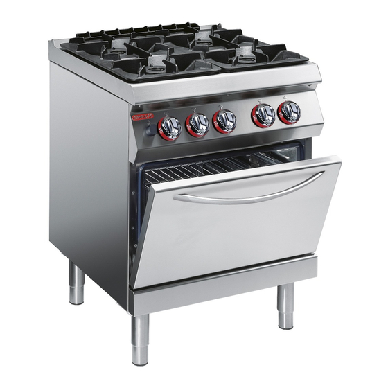
La cucina fuochi aperti con forno, d'ora innanzi de- In funzione delle esigenze di utilizzo, l'apparecchia- finita apparecchiatura, è stata progettata e costruita tura è prodotta in più versioni (vedi figura). per la preparazione e cottura di alimenti nell'ambito della ristorazione professionale. 1G1FA0G 2G1FA0G 2G1FADG IDM-39618300100.tif 1G1FABG 2G1FABG... - Page 8 Organi principali A)Piano di cottura: realizzato in acciaio inox. B)Bruciatori di piano: realizzati in ghisa smaltata, possono fornire potenze variabili in funzione della loro dimensione C)Scarico fumi: per evacuare i fumi del forno. D)Accensione piezoelettrica: per accendere il bru- ciatore del forno E)Manopola comando forno: serve per regolare l'alimentazione gas del bruciatore del forno F) Manopole comando bruciatori di piano: servono...
-
Page 9: Sicurezza
SEGNALI DI SICUREZZA E INFORMAZIONE L'illustrazione indica la posizione dei segnali applicati. A)Targa identificazione fabbricante e apparec- chiatura. B)Pericolo generico: prima di effettuare qualsiasi tipo di intervento, leggere attentamente il manuale. C)Pericolo generico: durante il lavaggio dell'apparec- chiatura non dirigere getti d'acqua in pressione sulle parti interne. - Page 10 salute delle persone, danni ai beni posti nelle vici- nizzazione e la pulizia dell'apparecchiatura con nanze e danni economici. l'uso di prodotti detergenti. – Tutti gli interventi di manutenzione che richiedono – Alla fine di ogni utilizzo, assicurarsi che i bruciatori una precisa competenza tecnica o particolari capa- siano spenti, con le manopole comando disattivate cità...
-
Page 11: Uso E Funzionamento
USO E FUNZIONAMENTO ISTRUZIONI E AVVERTENZE PER L’USO E FUNZIONAMENTO Importante Gli utilizzatori, oltre ad essere autorizzati ed Prima dell’uso verificare che i dispositivi di opportunamente documentati, formati ed sicurezza siano perfettamente installati ed addestrati, se necessario, al primo uso, do- efficienti. - Page 12 ACCENSIONE E SPEGNIMENTO BRUCIATORI DI PIANO Accensione 1 - Aprire il rubinetto alimentazione gas. 2 - Premere e ruotare la manopola (A) in senso an- tiorario (pos. 1) ed accendere la spia pilota. 3 - Mantenere premuta la manopola per circa 15 sec per consentire l'intervento della termocoppia.
-
Page 13: Manutenzioni
Spegnimento 2 - Ruotare la manopola in senso orario (pos. 4) 1 - Ruotare la manopola in senso orario per spegnere la spia pilota. (pos. 3) per spegnere il bruciatore. La spia pilo- 3 - Chiudere il rubinetto per garantire condizioni di ta rimarrà... - Page 14 PULIZIA APPARECCHIATURA Se si considera che l'apparecchiatura è utilizzata per 3 - Pulire gli accessori dopo l’uso, con uno sgras- sante idoneo. Si consiglia il lavaggio in lavasto- la preparazione di prodotti alimentari per l'uomo, è ne- viglie. cessario prestare particolare cura a tutto ciò che ri- guarda l'igiene e mantenere costantemente pulita Cautela - Avvertenza l'apparecchiatura e tutto l'ambiente circostante.
- Page 15 PULIZIA FORNO Per questa operazione procedere nel modo indica- 1 - Estrarre la suola (C) e la griglia (D) dal forno e pulirle accuratamente. 2 - Pulire le parti interne del forno da eventuali in- crostazioni che possano pregiudicarne il corret- to funzionamento.
-
Page 16: Guasti
Per qualsiasi esigenza rivolgersi alle agen- zie o alla sede centrale Angelo Po i cui rife- Alcuni di questi problemi possono essere risolti rimenti sono riportati nella sezione contatti dall’utilizzatore, per tutti gli altri è... -
Page 17: Movimentazione E Installazione
MOVIMENTAZIONE E INSTALLAZIONE ISTRUZIONI E AVVERTENZE PER LA MOVIMENTAZIONE E INSTALLAZIONE Importante Tutte le operazioni di movimentazione e di Chi è autorizzato ad eseguire queste opera- installazione dovranno essere eseguite nel zioni dovrà, se necessario, organizzare un rispetto della legislazione vigente in mate- "piano di sicurezza"... - Page 18 INSTALLAZIONE APPARECCHIATURA Tutte le fasi di installazione devono essere conside- rate sin dalla realizzazione del progetto generale. Prima di iniziare tali fasi, oltre alla definizione della zona di installazione, chi è autorizzato ad eseguire queste operazioni dovrà, se necessario, attuare un “piano di sicurezza”...
- Page 19 LIVELLAMENTO Agire sui piedi di appoggio (A) per livellare l'appa- recchiatura. IDM-39603610000.tif MONTAGGIO APPARECCHIATURE IN BATTERIA Per montare le apparecchiature in batteria (fianco a fianco) procedere nel modo indicato. 1 - Sfilare le manopole (A). 2 - Svitare le viti (C) e smontare i cruscotti (B). 3 - Applicare, sui bordi da accostare, del nastro adesivo di protezione.
- Page 20 ALLACCIAMENTO GAS Importante Chi è autorizzato ad effettuare tale operazio- ne deve possedere capacità ed esperienza acquisita e riconosciuta nel settore specifico, dovrà eseguire l'allacciamento a regola d'arte e tenere conto di tutti i requisiti normativi e le- gislativi. Ad allacciamento completato, prima di rendere operativa l'attrezzatura, si dovrà...
-
Page 21: Regolazioni
COLLAUDO APPARECCHIATURA 3 - verificare la regolare accensione e combustio- Importante ne dei bruciatori di piano e del bruciatore del Prima della messa in servizio, deve essere forno; eseguito il collaudo dell'impianto, al fine di 4 - verificare e, se necessario, regolare la pressio- valutare le condizioni operative di ogni sin- ne e la portata del gas al minimo e al massimo golo componente ed individuare le even-... - Page 22 Per questa operazione procedere nel modo indicato. adatto al tipo di gas utilizzato (vedi tabella in 1 - Chiudere il rubinetto alimentazione gas fondo al manuale). 2 - Sfilare le manopole (A). 5 - Dopo la regolazione sigillare la vite con vernice. 3 - Svitare le viti (C) e smontare il cruscotto (B).
- Page 23 REGOLAZIONE ARIA PRIMARIA BRUCIATORE DI PIANO Per questa operazione procedere nel modo indica- 4 - Allentare la vite (D) e sollevare il supporto bru- ciatore (E) fino a battuta. 1 - Chiudere il rubinetto alimentazione gas. 5 - Stringere la vite (D) e ripristinare le condizioni 2 - Sfilare le manopole (A).
-
Page 24: Sostituzione Parti
SOSTITUZIONE PARTI ISTRUZIONI E AVVERTENZE PER LA SOSTITUZIONE PARTI Prima di effettuare qualsiasi intervento di sosti- Qualora sia necessario sostituire dei componen- tuzione, attivare tutti i dispositivi di sicurezza ti usurati, utilizzare esclusivamente dei ricambi previsti e valutare se sia necessario informare originali. - Page 25 SOSTITUZIONE UGELLO SPIA PILOTA BRUCIATORE DI PIANO Per questa operazione procedere nel modo indicato. 5 - Estrarre l'ugello (E) e sostituirlo con quello 1 - Chiudere il rubinetto alimentazione gas. adatto al tipo di gas utilizzato (vedi tabella in 2 - Sfilare le manopole (A). fondo al manuale).
- Page 26 Caution - warning Important Never use products containing substances Make a daily check that the safety devices harmful or hazardous for health (solvents, are properly installed and in good working order. Make a daily check that the safety petroleum spirits, etc.). devices are properly installed and in good working order.
- Page 27 CONTENTS ref. chapters page 1 GENERAL INFORMATION ..........3 2 TECHNICAL INFORMATION..........5 3 SAFETY ................7 PART 4 USE AND OPERATION ............. 9 5 SERVICING ..............11 6 FAULT ................14 7 HANDLING AND INSTALLATION ........15 8 ADJUSTMENTS............... 19 PART 9 REPLACING PARTS ............
- Page 28 Top burner, replacing pilot light Troubleshooting, 14 Technical data, 5 nozzle, 23 Testing of the appliance, 19 Unpacking and packaging, 15 Top burner, switching on and off, 10 Top burner pilot light, nozzle Transport, 15 replacement, 23 - 2 - English...
-
Page 29: General Information
GENERAL INFORMATION INSTRUCTIONS AND WARNINGS FOR THE READER To find the specific topics of interest to you quickly, part: contains all the information neces- refer to the index at the start of the manual. sary for special categories of reader, i.e. all This manual is subdivided into two parts. - Page 30 IDM-39614500100.tif PROCEDURE FOR REQUESTING SERVICE For all requirements contact the agents or the head- quarters of Angelo Po which can be found in the contacts section of the website http:// www.angelo- po.com. When requesting service, state the data provide on the nameplate and provide a description of the fault.
-
Page 31: Technical Information
The appliance is produced in several versions to now on as the appliance, is designed and construct- meet varying user requirements (see diagram). ed for preparing and cooking foods in the profes- sional catering sector. 1G1FA0G 2G1FA0G 2G1FADG IDM-39618300100.tif 1G1FABG... - Page 32 Main Parts A)Hob: in stainless steel. B)Top burners: in enamelled cast iron, the power they are able to supply varies depending on their size. C)Fume exhaust vent: for removal of the fumes from the oven. D)Piezoelectric ignition: lights the oven burner E)Oven control knob: regulates the gas supply to the oven burner F) Top burner control knobs: regulate the gas supply...
-
Page 33: Safety
SAFETY AND INFORMATION SIGNS The illustration shows the position of the signs pro- vided. A)Nameplate with manufacturer and appliance data. B)General hazard: read the manual carefully be- fore carrying out any procedure. C)General hazard: when washing the appliance do not point pressurised water jets at internal parts. D)General hazard: all relevant regulations must be complied with. - Page 34 – All maintenance work that requires precise, tech- – In the event of lengthy periods out of use, thor- nical expertise or particular skills or qualifications oughly clean all internal and external parts of the for legal reasons,should be carried out by suita- appliance and the surrounding area (in accord- bly trained and/or qualified staff and in any case ance with the manufacturer’s instructions) and...
-
Page 35: Use And Operation
USE AND OPERATION INSTRUCTIONS AND WARNINGS FOR USE AND OPERATION Important Besides being authorised and appropriately Before use, check that the safety devices are documented,and if necessary,instructed and properly installed and in good working order. trained, users,on fi rst usage, have to simulate As well as taking care to meet these require- several operations to identify the controls and ments, users must also implement all safety... - Page 36 SWITCHING THE TOP BURNER ON AND OFF Lighting 1 - Turn on the gas supply tap. 2 - Press the knob (A) and turn it anti-clockwise (pos. 1) to light the pilot light. 3 - Keep the knob pressed for about 15 sec. to prime the thermocouple.
-
Page 37: Servicing
Turning off 2 - Turn the knob clockwise (pos. 4) to turn off the 1 - Turn the knob clockwise (pos. 3) to turn the pilot light. burner off. The pilot light will remain on to allow 3 - Turn off the knob to ensure safety. the burner to be re-lit. - Page 38 CLEANING INSTRUCTIONS Since the appliance is used for preparing foods for grease-remover product. If possible, wash in human consumption, special care must be paid to the dishwasher. everything relating to hygiene, and the appliance Caution - warning and the entire surrounding environment must con- Do not wash cast iron parts such as the bur- stantly be kept clean ners, burner caps and grills in a dishwasher.
- Page 39 CLEANING OVEN To carry out this operation, proceed as follows. 1 - Remove the bottom plate (C) and the grid (D) from the oven and clean them thoroughly. 2 - Clean the inside parts of the oven to remove any deposits which may impair its operation. 3 - Dry the surfaces and reassemble the compo- nents.
-
Page 40: Fault
For all requirements contact the agents or the headquarters of Angelo Po which can use. be found in the contacts section of the web- The user can solve some of these problems him- site http://www.angelopo.com. -
Page 41: Handling And Installation
HANDLING AND INSTALLATION INSTRUCTIONS AND WARNINGS FOR HANDLING AND INSTALLATION Important All handling and installation operations If necessary, the person authorised to carry should be carried out in accordance with cur- out these operations must organise a "safety rent legislation on health and safety at work. plan"... - Page 42 INSTALLATION OF THE APPLIANCE All installation stages must be considered right from production of the general layout. Before starting these stages, as well as deciding the place of instal- lation, if necessary, the person authorised to carry out these operations must organise a "safety plan" to protect the people directly involved, and he must also ensure strict compliance with all legal require- ments, especially those relating to mobile work-...
- Page 43 LEVELLING Adjust the floor-mounted feet (A) to level the appli- ance. IDM-39603610000.tif ASSEMBLY APPLIANCES IN BANKS To assemble appliances in banks (side by side) pro- ceed as described below. 1 - Pull off the knob (A). 2 - Undo the screws (C) and remove the control pan- els (B).
- Page 44 GAS CONNECTION Important Those authorised to carry out this opera- tion must have experience acquired and certified in the specific sector, must make the connection to the proper standards, and must comply with all the relevant regu- lations and legislation. Once the connec- tion has been made, before the appliance is put into operation a general check must be made to ensure there are no gas leaks.
-
Page 45: Adjustments
TESTING OF THE APPLIANCE 3 - Check that the top and oven burners are light- Important ing correctly and their combustion. Before it is put into service, the system 4 - Check the gas pressure and flow-rate at mini- must be tested to check the operating con- mum and maximum settings and adjust if nec- ditions of every single component and essary (see page 13). - Page 46 To carry out this operation, proceed as follows. one suitable for the type of gas in use (see table 1 - Turn off the gas supply tap. at back of manual). 2 - Pull off the knob (A). 5 - After making the setting, seal the screw with 3 - Undo the screws (C) and remove the control paint.
- Page 47 ADJUSTING TOP BURNER PRIMARY AIR To carry out this operation, proceed as follows. 4 - Undo the screw (D) and lift the burner support 1 - Turn off the gas supply tap. (E) as far as it will go. 2 - Pull off the knob (A). 5 - Tighten the screw (D) and restore the initial 3 - Undo the screws (C) and remove the control conditions when the operation is complete.
-
Page 48: Replacing Parts
REPLACING PARTS INSTRUCTIONS AND WARNINGS FOR REPLACING PARTS Before carrying out any replacement procedure, ac- clines all responsibly for injury or damage to com- tivate all the safety devices provided and decide ponents due to the use of non original parts, or whether staff at work and those in the vicinity extraordinary work on the appliance which may should be informed. - Page 49 REPLACING THE TOP BURNER PILOT LIGHT NOZZLE To carry out this operation, proceed as follows. 5 - Remove the nozzle (E) and replace it with the 1 - Turn off the gas supply tap. one suitable for the type of gas in use (see table 2 - Pull off the knob (A).
- Page 50 Vorsicht - Achtung Wichtig Verwenden Sie keine Produkte, die Stoff e en- Stellen Sie jeden Tag durch Kontrollen si- thalten, welche für die menschliche Gesun- cher, dass die Sicherheitsvorrichtungen fa- chgerecht installiert sind und einwandfrei dheit schädlich gefährlich sind funktionieren. (Lösemittel, Benzin, usw.).
- Page 51 INHALTSVERZEICHNIS Ref. Kapitel Seite 1 ALLGEMEINES..............3 2 TECHNISCHE INFORMATIONEN........5 3 SICHERHEIT ..............7 1. TEIL 4 GEBRAUCH UND BETRIEB..........9 5 WARTUNG............... 11 6 DEFEKTE................. 14 7 HANDHABUNG UND INSTALLATION ......15 8 EINSTELLUNGEN ............19 2. TEIL 9 AUSTAUSCH VON BAUTEILE ........
- Page 52 und Gerät, 4 Nivellieren, 17 Schmierung des Gashahns, 21 Sicherheitshinweise und Umstellung der Gasversorgung, 18 Optionales Zubehör, 7 Informationen, 7 Verpackung und Auspacken, 15 Raumbelüftung, 16 Sicherheitsvorrichtungen, 6 Zündflammenbrenner des Reinigung der Kochmulde, Brenner Technische Daten, 6 Kochstellenbrenners, Austausch der und Zubehörteile, 12 Testlauf zur Abnahme des Geräts, 19 Düse, 23...
-
Page 53: Allgemeines
ALLGEMEINES ANWEISUNGEN UND WARNHINWEISE FÜR DEN LESER Konsultieren Sie das Sachregister, das am Anfang 2. Teil: Diese Informationen wenden sich an des Handbuchs zu finden ist, um leichter unter be- eine bestimmte Zielgruppe. Sie sind für erfahre- stimmten Themen von besonderem Interesse ne Bediener bestimmt, die für Handhabung, nachschlagen zu können. - Page 54 TYPENSCHILD FÜR HERSTELLER UND GERÄT Das abgebildete Typenschild wird direkt auf dem ) Gastyp ) Angabe der Leistung (Kw) Gerät aufgebracht. Es enthält sämtliche Angaben ) Gasverbrauch und Hinweise, die für den sicheren Betrieb unerläs- ) Testgasanzeige slich sind. ) Baujahr Ergänzungsschild Testgasschild ) Benutzerland...
-
Page 55: Technische Informationen
Der Gasherd mit offenen Flammen + Backofen, der Das Gerät wird bedarfsabhängig in verschiedenen im Folgenden als Gerät bezeichnet wird, wurde Versionen hergestellt (siehe Abbildung). zum Zubereiten und Garen von Speisen in Restau- rantbetrieben projektiert und konstruiert. 1G1FA0G 2G1FA0G 2G1FADG IDM-39618300100.tif 1G1FABG 2G1FABG... - Page 56 Hauptorgane A)Kochmulde: aus Edelstahl. B)Kochstellenbrenner: aus emailliertem Gussei- sen, Heizleistung von Größe abhängig C)Wrasenöffnung: für den Austritt des Dampfes aus dem Backofen. D)Piezozündung: zum Zünden des Backofenbren- ners E)Backofen-Schalter: zum Einstellen der Heizlei- stung des Backofens F) Schalter der Kochstellenbrenner: zum Einstel- len der Heizleistung der Kochstellenbrenner G)Backofen mit Thermostat: aus Stahl, mit dich- ter Tür und Isoliergriff...
-
Page 57: Sicherheit
SICHERHEITSHINWEISE UND INFORMATIONEN Die Abbildung zeigt die Anordnung der aufgekleb- ten Sicherheitshinweise. A)Typenschild mit Angabe des Herstellers und der Gerätekenndaten. B)Allgemeine Gefahr: Vor Ausführung irgendeines Eingriffs zuerst das Handbuch aufmerksam lesen. C)Allgemeine Gefahr: Beim Waschen des Geräts den Wasserstrahl nicht direkt auf die inneren Tei- le richten. - Page 58 wichtigsten Funktionen vertraut zu machen. schriebene persönliche Schutzausrüstung – Setzen Sie das Gerät nur für die vom Hersteller (Schutzhandschuhe, Atemschutzmaske, Schutz- vorgesehenen Verwendungszwecke ein. Die un- brille usw.) tragen. . sachgemäße Verwendung des Gerätes kann so- – Stellen Sie nach jeder Verwendung sicher, dass wohl die Sicherheit als auch die Gesundheit der die Brenner ausgeschaltet sind, wobei die Bedi- Personen gefährden, Gegenstände, die sich in...
-
Page 59: Gebrauch Und Betrieb
GEBRAUCH UND BETRIEB ANWEISUNGEN UND WARNHINWEISE FÜR DIE GEBRAUCH UND BETRIEB Wichtig Die Anwender müssen nicht nur befugt und an- Überprüfen Sie vor dem Gebrauch, ob die Si- gemessen informiert, ausgebildet und geschult cherheitsvorrichtungen installiert sind und ein- sein sondern ggf. auch beim ersten Einsatz des wandfrei funktionieren. - Page 60 EIN- UND AUSSCHALTEN DER KOCHSTELLENBRENNER Zündung 1 - Öffnen Sie den Gashahn. 2 - Den Schalter (A) niederdrücken und entgegen dem Uhrzeigersinn drehen (Pos. 1) und die Zündflamme zünden. 3 - Halten Sie den Bedienknebel etwa 15 Sekun- den lang gedrückt, damit das Thermoelement in Aktion treten kann.
-
Page 61: Wartung
Abschaltung 2 - Drehen Sie den Bedienknebel im Uhrzeigersinn 1 - Drehen Sie den Bedienknebel im Uhrzeigersinn (Pos. 4), um den Zündflammenbrenner auszu- (Pos. 3), um den Brenner abzuschalten. Der schalten. Zündflammenbrenner bleibt für die folgenden 3 - Drehen Sie den Gashahn ab, um die Sicher- Zündungen des Brenners eingeschaltet. - Page 62 REINIGUNG DES GERÄTS Da das Gerät zur Zubereitung von Speisen für den nem geeigneten Fettlöser reinigen. Wir em- pfehlen die Reinigung im Geschirrspüler. Menschen eingesetzt wird, ist besondere Sorgfalt auf die Hygiene geboten. Das Gerät und dessen näheres Vorsicht - Achtung Umfeld müssen konstant sauber gehalten werden.
- Page 63 REINIGUNG DES BACKOFENS Für diesen Vorgang in der angegebenen Weise verfahren. 1 - Den Rost (C) und das Bodenblech (D) aus dem Backofen nehmen und gründlich reinigen. 2 - Die Teile im Backofen von Verkrustungen reini- gen, die seine Funktionsfähigkeit beeinträchti- gen könnten.
-
Page 64: Defekte
Bei Rückfragen wenden Sie sich bitte an die Handelsvertretungen oder den Hauptsi- treten können, aufzufinden und zu beheben. tz des Unternehmens Angelo Po, die ent- Einige dieser Probleme können vom Benutzer sprechenden Kontaktdaten sind auf der selbst behoben werden; alle anderen erfordern prä- Webseite http://www.angelopo.com unter... -
Page 65: Handhabung Und Installation
HANDHABUNG UND INSTALLATION ANWEISUNGEN UND WARNHINWEISE FÜR DIE INSTALLATION UND HANDHABUNG Wichtig Alle Transport- und Aufstellungsarbeiten Die für diese Operationen autorisierte Per- müssen unter Berücksichtigung der gelten- son wird bei Bedarf einen "Sicherheits- den gesetzlichen Vorschriften zur Gesund- plan" aufstellen müssen, heit Sicherheit... - Page 66 INSTALLATION DES GERÄTS Es müssen sämtliche Phasen der Installation, schon von der Umsetzung des allgemeinen Projekts an, berücksichtigt werden. Die für diese Operationen au- torisierte Person wird vor Einleitung dieser Phasen den Installationsstandort bestimmen und bei Bedarf einen "Sicherheitsplan" aufstellen, um die Unver- sehrtheit der direkt am Vorgang beteiligten Personen zu gewährleisten und die gesetzlichen Bestimmun- gen zu befolgen.
- Page 67 NIVELLIEREN Regulieren Sie die Füße (A), um das Gerät wasser- waagengerecht aufzustellen. IDM-39603610000.tif MONTAGE BEI REIHENAUFSTELLUNG Verfahren Sie folgendermaßen, um Geräte (neben- einander) in einer Reihe aufzustellen. 1 - Den Schalter (A) abziehen. 2 - Die Schrauben (C) ausschrauben und die Blen- den (B) ausbauen.
- Page 68 GASANSCHLUSS Wichtig Diese Arbeit darf nur von zugelassenen und er- fahrenen Fachleuten ausgeführt werden. Der Anschluss muss fachgerecht und vorschrifts- mäßig ausgeführt werden und allen einschlägi- gen gesetzlichen Bestimmungen entsprechen. Nach Ausführung des Anschlusses muss vor der Inbetriebnahme des Geräts durch eine all- gemeine Kontrolle sichergestellt werden, dass nirgends Gas austritt.
-
Page 69: Einstellungen
TESTLAUF ZUR ABNAHME DES GERÄTS und beim Backofenbrenner ordnungsgemäß Wichtig erfolgen. 4 - Überprüfen Sie Gasdruck und –durchsatz bei Vor der Inbetriebnahme muss ein Testlauf der Anlage durchgeführt werden, um den minimaler und maximaler Zufuhr und regulieren Betriebszustand jeder einzelnen Kompo- Sie, falls notwendig, die Einstellungen (siehe nente zu überprüfen und eventuelle An- Seite 13). - Page 70 Für diesen Vorgang in der angegebenen Weise die verwendete Gasart geeignete Düse erset- verfahren. zen (siehe die Tabelle am Ende des Hand- 1 - Schließen Sie den Gaszufuhrhahn buchs). 2 - Den Schalter (A) abziehen. 5 - Versiegeln Sie die Schraube nach Abschluss 3 - Drehen Sie die Schrauben (C) heraus und der Einstellung mit Lack.
- Page 71 EINSTELLUNG DER PRIMÄRLUFT DES KOCHSTELLENBRENNERS Für diesen Vorgang in der angegebenen Weise 4 - Die Schraube (D) lockern und die Brennerhalte- verfahren. rung (E) bis zum Anschlag anheben. 1 - Schließen Sie den Gaszufuhrhahn 5 - Abschließend die Schraube (D) festziehen und 2 - Den Schalter (A) abziehen.
-
Page 72: Austausch Von Bauteile
AUSTAUSCH VON BAUTEILE ANWEISUNGEN UND WARNHINWEISE FÜR DAS AUSWECHSELN VON BAUTEILEN Vor jedem Eingriff zur Ersetzung eines Teils müssen bei Bedarf Komponenten, die Verschleißerscheinun- sämtliche vorgesehenen Sicherheitsvorrichtungen ak- gen zeigen; verwenden Sie dabei ausschließlich Ori- tiviert werden. Überlegen Sie, ob es notwendig ist, das ginalersatzteile.Es wird jede Haftung für Personen- arbeitende Personal und die in der Nähe befindlichen oder Komponentenschäden abgelehnt, die entstehen,... - Page 73 AUSTAUSCH DER DÜSE DES ZÜNDFLAMMENBRENNERS DES KOCHSTELLENBRENNERS Für diesen Vorgang in der angegebenen Weise 5 - Nehmen Sie die Düse (E) heraus und ersetzen verfahren. Sie sie mit dem für den betreffenden Gastyp 1 - Schließen Sie den Gaszufuhrhahn geeigneten Bauteil (siehe Tabelle am Ende des 2 - Den Schalter (A) abziehen.
- Page 74 Attention Important Ne pas utiliser de produits qui contiennent Vérifier quotidiennement que les disposi- des substances dangereuses pour la santé tifs de sécurité soient parfaitement instal- lés et efficaces. des personnes (solvants, essences, etc.). Attention Attention Le sol, à proximité de l’appareil, pourrait être Avant toute intervention, couper l’alimenta- glissant.
- Page 75 INDEX réf. chapitres page 1 INFORMATIONS GENERALES......... 3 2 INFORMATIONS TECHNIQUES ........5 3 SÉCURITÉ ................. 7 PARTIE 4 UTILISATION ET FONCTIONNEMENT ......9 5 ENTRETIEN..............11 6 PANNES ................14 7 MANUTENTION ET INSTALLATION....... 15 8 RÉGLAGES ..............19 PARTIE 9 REMPLACEMENT DE PIÈCES ........
- Page 76 fourneau, remplacement de la sécurité et information, Transformation de l’alimentation, 18 buse, 23 Transport, 15 signaux de, 7 Ventilation de la pièce, 16 sécurité, dispositifs de, 6 Veilleuse pilote du brûleur Signaux de sécurité et information, 7 - 2 - Français...
- Page 77 INFORMATIONS GENERALES INSTRUCTIONS ET AVERTISSEMENTS POUR LE LECTEUR Pour retrouver facilement les sujets qui vous inté- partie: elle contient toutes les informations ressent, consulter l’index analytique au début du nécessaires aux destinataires homogènes, manuel. c’est-à-dire tous les opérateurs experts et Ce manuel est divisé...
- Page 78 IDM-39614500100.tif DEMANDE D'ASSISTANCE Pour toute exigence, s’adresser aux agences ou au siège centra Angelo Po dont les références sont re- portées dans la section contacts du site internet http://www.angelopo.com. Pour toute demande d’assistance technique, indi- quer les données reportées sur la plaque d’identifi- cation et le type de défaut relevé.
- Page 79 En fonction des exigences d'utilisation, l'appareil maintenant appareil, a été conçu et fabriqué pour la est réalisé en plusieurs versions (voir figure). préparation et la cuisson d’aliments dans le domai- ne de la restauration professionnelle. 1G1FA0G 2G1FA0G 2G1FADG IDM-39618300100.tif 1G1FABG...
- Page 80 Organes principaux A)Plan de travail: en acier inox. B)Brûleurs fourneau : en fonte émaillée, ils peuvent fournir des puissances variables en fonction de leur dimension. C)Evacuation des fumées : pour évacuer les fumées du four. D)Allumage piézoélectrique: pour allumer le brûleur du four E)Manette de commande du four: pour régler l’alimen- tation du gaz du brûleur du four...
- Page 81 SIGNAUX DE SÉCURITÉ ET INFORMATION L’illustration indique la position des signaux appli- qués. A)Plaque d'identification du fabricant et de l'ap- pareil. B)Danger générique: avant tout type d’intervention, lire attentivement ce manuel. C)Risque générique: pendant le lavage de l’appareil ne pas diriger de jets d’eau sous pression sur les piè- ces intérieures.
- Page 82 pour des utilisations incorrectes peut provoquer rité et de santé, à chaque désinfection et nettoya- des risques pour la sécurité et la santé des per- ge de l'appareil avec des produits détergents. . sonnes, des dommages aux biens placés à –...
- Page 83 UTILISATION ET FONCTIONNEMENT INSTRUCTIONS ET AVERTISSEMENTS POUR L'UTILISATION ET FONCTIONNEMENT Important Les utilisateurs, en plus d’être autorisés et Avant l’utilisation, vérifi er si les dispositifs documentés de façon appropriée, formés et de sécurité sont parfaitement installés et entraînés, si nécessaire, lors de la première efficaces.
- Page 84 ALLUMAGE ET EXTINCTION BRÛLEURS FOURNEAU Allumage 1 - Ouvrir le robinet d’alimentation du gaz. 2 - Pousser et tourner la manette (A) en sens anti- horaire (pos. 1) pour allumer la veilleuse pilote. 3 - Continuer à appuyer sur la manette pendant environ 15 s pour permettre l’intervention du thermocouple.
- Page 85 Extinction 2 - Tourner la manette en sens horaire (pos. 4) 1 - Tourner la manette en sens horaire (pos. 3) pour éteindre la veilleuse pilote. pour éteindre le brûleur. La veilleuse pilote res- 3 - Fermer le robinet pour garantir les conditions tera allumée pour des rallumages successifs du de sécurité.
- Page 86 NETTOYAGE DE L’APPAREIL Etant donné que l'appareil est utilisé pour la prépa- 3 - Nettoyer les accessoires après leur utilisation avec un dégraissant approprié. Le lavage en ration de produits alimentaires pour l'homme, il faut lave-vaisselle est conseillé. faire attention à tout ce qui concerne l'hygiène ; l'appareil et tout ce qui l'entoure doivent toujours Attention être très propres.
- Page 87 NETTOYAGE DU FOUR Pour cette opération, procéder comme suit. 1 - Extraire la sole (C) et la grille (D) du four et les nettoyer soigneusement. 2 - Enlever les éventuelles incrustations des par- ties internes du four car elles pourraient gêner son fonctionnement correct.
- Page 88 Pour toute exigence, s’adresser aux agen- ces ou au siège centra Angelo Po dont les Certains de ces problèmes peuvent être résolus par références sont reportées dans la section l’utilisateur, pour tous les autres il faut une compé-...
- Page 89 MANUTENTION ET INSTALLATION INSTRUCTIONS ET AVERTISSEMENTS POUR LA MANUTENTION ET L’INSTALLATION Important Toutes les opérations de déplacement et Celui qui est autorisé à effectuer ces opéra- d’installation devront être effectuées dans tions devra, si nécessaire, organiser un le respect de la législation en vigueur en «...
- Page 90 MISE EN PLACE DE L’APPAREIL Toutes les phases de mise en place doivent être prises en considération, dès la réalisation du projet général. Avant de commencer ces phases, outre la définition de la zone de mise en place, celui qui est autorisé...
- Page 91 MISE À NIVEAU Agir sur les pieds d’appui (A) pour mettre de niveau l’appareil. IDM-39603610000.tif MONTAGE DES APPAREILS EN BATTERIE Pour monter les appareils en batterie (les uns à côté des autres), procéder comme suit. 1 - Enlever la manette (A). 2 - Dévisser les vis (C) et démonter les tableaux de commandes (B).
- Page 92 RACCORDEMENT DU GAZ Important La personne autorisée à effectuer cette opération devra avoir les capacités et l’ex- périence acquise et reconnue dans le sec- teur spécifique; elle devra effectuer le raccordement dans les règles de l’art et te- nir compte de toutes les exigences impo- sées par les normes et les lois.
- Page 93 ESSAI DE L’APPAREIL 3 - Vérifier l’allumage régulier et la combustion des Important brûleurs fourneau et du brûleur du four. Avant la mise en service, l’essai de l’instal- 4 - Vérifier et, si nécessaire, régler la pression et le lation doit être fait pour évaluer les condi- débit du gaz au minimum et au maximum (voir tions opérationnelles...
- Page 94 Pour cette opération, procéder comme suit. adapté au type de gaz utilisé (voir tableau à la 1 - Fermer le robinet d’alimentation du gaz. fin du manuel). 2 - Enlever la manette (A). 5 - Après le réglage sceller la vis avec du vernis. 3 - Dévisser les vis (C) et démonter le tableau de 6 - Remonter le tableau de commandes (B) et les commandes (B).
- Page 95 RÉGLAGE DE L’AIR PRIMAIRE DU BRÛLEUR FOURNEAU Pour cette opération, procéder comme suit. 4 - Desserrer la vis (D) et lever le support du brû- 1 - Fermer le robinet d’alimentation du gaz. leur (E) jusqu’à la butée. 2 - Enlever la manette (A). 5 - Serrer la vis (D) et rétablir les conditions initia- 3 - Dévisser les vis (C) et démonter le tableau de les lorsque l’opération est terminée.
- Page 96 REMPLACEMENT DE PIÈCES INSTRUCTIONS ET AVERTISSEMENTS POUR LE REMPLACEMENT DES PIÈCES Avant d’effectuer tout remplacement, activer tous ge d’origine.Le fabricant décline toute responsabili- les dispositifs de sécurité prévus et évaluer s’il faut té pour des dommages à des personnes ou à des informer les opérateurs travaillant sur l'appareil et composants dérivant de l’utilisation de pièces de re- ceux à...
- Page 97 REMPLACEMENT DE LA BUSE VEILLEUSE PILOTE DU BRÛLEUR FOURNEAU Pour cette opération, procéder comme suit. 5 - Enlever la buse (E) et la remplacer par celle 1 - Fermer le robinet d’alimentation du gaz. adaptée au type de gaz utilisé (voir tableau à la 2 - Enlever la manette (A).
- Page 98 Precaución - advertencia Importante No usar productos que contengan sustan- Controlar periódicamente que los equipos cias nocivas y/o peligrosas para la salud de de seguridad se encuentren en perfecto es- tado y estén correctamente instalados. las personas (disolventes, bencinas, etc.). Precaución - advertencia Precaución - advertencia El pavimento, cerca del equipo, podría ser...
- Page 99 ÍNDICE ref. capítulos pág 1 ÍINFORMACIONES DE CARÁCTER GENERAL ....3 2 INFORMACIONES DE CARÁCTER TÉCNICO ....5 3 SEGURIDAD ..............7 PARTE 4 USO Y FUNCIONAMIENTO ..........9 5 MANTENIMIENTO ............11 6 AVERÍAS................14 7 DESPLAZAMIENTO E INSTALACIÓN ......15 8 REGULACIONES.............
- Page 100 Regulación del mínimo válvula gas información, 7 Testigo piloto quemador de plano, (horno), 20 Sustitución inyector del quemador cambio inyector, 23 Regulación mínimo llave con válvula horno, 22 Transformación alimentación, 18 de seguridad gas (quemadores del Sustitución inyector testigo piloto Transporte, 15 plano), 19 quemador de plano, 23...
-
Page 101: Íinformaciones De Carácter General
INFORMACIONES DE CARÁCTER GENERAL INSTRUCCIONES Y ADVERTENCIAS PARA EL LECTOR Para ubicar fácilmente los temas específicos de in- 2a parte: contiene todas las informaciones ne- cesarias para destinatarios homogéneos, esto terés, consúltese el índice analítico que se encuen- es, todos los operadores expertos y autoriza- tra al inicio del manual. - Page 102 ) Tipo de familia del producto IDM-39614500100.tif MODALIDAD PARA REQUERIR ASISTENCIA Para cualquier necesidad, diríjase a las agencias o a la sede central de Angelo Po, cuyos referentes se indican en la sección de contactos del sitio web http://www.angelopo.com. Para solicitar asistencia técnica deberán indicarse los datos reproducidos en la placa de identificación...
-
Page 103: Informaciones De Carácter Técnico
(véa- da y fabricada para la preparación y la cocción de se figura). alimentos en el sector de la restauración profesio- nal. 1G1FA0G 2G1FA0G 2G1FADG IDM-39618300100.tif 1G1FABG 2G1FABG - 5 - Español... - Page 104 Órganos principales A)Encimera: fabricada en acero inox. B)Quemadores de plano: realizados en fundición es- maltada, pueden proporcionar potencias variables en función de sus dimensiones C)Salida de humos: para evacuar los humos genera- dos por el horno. D)Encendido piezoeléctrico: para encender el que- mador del horno E)Mando de control horno: para regular la alimenta- ción de gas del quemador del horno...
-
Page 105: Seguridad
SEÑALIZACIONES DE SEGURIDAD E INFORMACIÓN La ilustración indica la posición de las señalizacio- nes fijadas en el equipo. A)Placa de identificación fabricante y aparato. B)Peligro genérico: antes de efectuar cualquier tipo de intervención leer atentamente el manual. C)Peligro genérico: durante el lavado del aparato no dirigir chorros de agua a presión hacia sus partes in- ternas. - Page 106 bienes situados en los alrededores y daños eco- normas vigentes sobre seguridad y salud. . nómicos. – Al final de cada utilización, controlar que los que- – Todas las operaciones de mantenimiento que re- madores estén apagados, con los mandos des- quieran una competencia técnica específica o activados líneas...
-
Page 107: Uso Y Funcionamiento
USO Y FUNCIONAMIENTO INSTRUCCIONES Y ADVERTENCIAS PARA EL USO Y FUNCIONAMIENTO Importante Los utilizadores, además de estar autoriza- Antes del uso, controlar que los dispositi- dos y oportunamente documentados, for- vos de seguridad estén instalados de forma mados y adiestrados, si fuera necesario, correcta y eficaz. - Page 108 ENCENDIDO Y APAGADO QUEMADORES DE PLANO Encendido 1 - Abrir el grifo de alimentación del gas. 2 - Presionar y girar el mando (A) en sentido anti- horario (pos. 1) y encender el testigo piloto. 3 - Mantener presionado el mando durante aprox. 15 s para obtener la intervención del termopar.
-
Page 109: Mantenimiento
Apagado 2 - Para apagar el testigo piloto, girar el mando en 1 - Para apagar el quemador, girar el mando en el el sentido de las agujas del reloj (pos. 4). sentido de las agujas del reloj (pos. 3). El testi- 3 - Cerrar el grifo a fin de garantizar condiciones go piloto permanecerá... - Page 110 LIMPIEZA APARATO Atendida la circunstancia de que el equipo es utili- 3 - Limpiar los accesorios después del uso utili- zando un desengrasante adecuado. Se acon- zado para la preparación de productos alimenticios seja efectuar el lavado en lavavajillas. para el consumo humano, es necesario prestar es- pecial atención a todo lo referente a la higiene, Precaución - advertencia manteniendo siempre limpio tanto el equipo como...
- Page 111 LIMPIEZA HORNO Para efectuar esta operación, aplicar las siguientes instrucciones. 1 - Extraer la solera (C) y la rejilla (D) del horno y limpiarlas esmeradamente. 2 - Limpiar las partes internas del horno a fin de eli- minar incrustaciones que podrían impedir su correcto funcionamiento.
-
Page 112: Averías
Para cualquier necesidad, diríjase a las agencias o a la sede central de Angelo Po, durante el uso. cuyos referentes se indican en la sección Algunos de estos problemas pueden ser resueltos de contactos del sitio web http://www.ange-... -
Page 113: Desplazamiento E Instalación
DESPLAZAMIENTO E INSTALACIÓN INSTRUCCIONES Y ADVERTENCIAS PARA EL DESPLAZAMIENTO Y LA INSTALACIÓN Importante Efectuar el desplazamiento e instalación rizada para efectuar estas operaciones de- respetando las indicaciones proporciona- berá, si fuera necesario, organizar un "plan das por el fabricante, reproducidas directa- de seguridad", a fin de salvaguardar la in- mente sobre el embalaje, en el equipo y en columidad de las personas directamente... - Page 114 INSTALACIÓN DEL EQUIPO Durante la realización del proyecto general, deben ser consideradas todas las fases de la instalación. Antes de comenzar dichas fases, además de esta- blecer la zona de instalación, la persona autorizada a efectuar estas operaciones deberá, si fuera nece- sario, aplicar un "plan de seguridad"...
- Page 115 NIVELACIÓN Operar con las patas de apoyo (A) para nivelar el equipo. IDM-39603610000.tif MONTAJE DE EQUIPOS EN BATERÍA Para montar los equipos en batería (uno al lado del otro) aplicar las siguientes instrucciones. 1 - Retirar el mando (A). 2 - Desenroscar los tornillos (C) y desmontar los paneles de mando (B).
- Page 116 ENLACE GAS Importante El personal autorizado para ejecutar esta opera- ción debe poseer capacidad y haber adquirido ex- periencia efectiva en el sector específico; la conexión deberá ejecutarse respetando rigurosa- mente todos los requisitos establecidos por las normativas vigentes. Una vez efectuada la co- nexión, antes de poner en funcionamiento el apa- rato se deberá...
-
Page 117: Regulaciones
PRUEBA DE FUNCIONAMIENTO DEL EQUIPO 3 - Controlar el correcto encendido y combustión Importante de los quemadores de plano y del quemador Antes de la puesta en servicio debe efec- del horno. tuarse la prueba de funcionamiento del sis- 4 - Controlar y, si fuera necesario, regular la pre- tema, a fin de evaluar las condiciones sión y el caudal del gas al mínimo y al máximo operativas de cada uno de sus componen-... - Page 118 Para efectuar esta operación, aplicar las siguientes sea adecuado para el tipo de gas utilizado instrucciones. (véase tabla al final del manual). 1 - Cerrar el grifo de alimentación del gas. 5 - Una vez efectuada la regulación sellar el torni- 2 - Retirar el mando (A).
- Page 119 REGULACIÓN AIRE PRIMARIO QUEMADOR DE PLANO Para efectuar esta operación, aplicar las siguientes 4 - Afloje el tornillo (D) y eleve el soporte quema- instrucciones. dor (E) hasta topar. 1 - Cerrar el grifo de alimentación del gas. 5 - Para concluir, apriete el tornillo (D) y restablez- 2 - Retirar el mando (A).
-
Page 120: Sostitución De Piezas
SOSTITUCIÓN DE PIEZAS INSTRUCCIONES Y ADVERTENCIAS PARA EFECTUAR LA SUSTITUCIÓN DE LAS PIEZAS Antes de efectuar cualquiera operación de sustitu- se deberán utilizar exclusivamente piezas de re- ción, activar todos los dispositivos de seguridad cambio originales. Se declina toda responsabilidad previstos y evaluar la conveniencia de informar por daños a personas o a componentes del equipo adecuadamente tanto al personal operativo como... - Page 121 SUSTITUCIÓN INYECTOR TESTIGO PILOTO QUEMADOR DE PLANO Para efectuar esta operación, aplicar las siguientes 4 - Retirar el tubo (D). instrucciones. 5 - Extraer el inyector (E) y sustituirlo por otro que 1 - Cerrar el grifo de alimentación del gas. sea adecuado para el tipo de gas utilizado 2 - Retirar el mando (A).
- Page 123 (Min. 1,1 kW) G25.3 1G1FA0G N. 1 N. 3 N. 1 2,96 m /h 3,45 m 2,21 kg/h 2,18 kg/h SCHEDA ALLACCIAMENTI (1G1FA0G) - CONNECTION CARD (1G1FA0G) - ANSCHLUSSSCHEMA (1G1FA0G) - FICHE DES RACCORDEMENTS (1G1FA0G) - FICHA DE ENLACES (1G1FA0G) IDM-39618301900.tif...
- Page 124 (Min. 1,9 kW) (Min. 1,1 kW) G25.3 1G1FABG N. 4 N. 1 3,17 m /h 3,69 m 2,37 kg/h 2,33 kg/h SCHEDA ALLACCIAMENTI (1G1FA0G) - CONNECTION CARD (1G1FA0G) - ANSCHLUSSSCHEMA (1G1FA0G) - FICHE DES RACCORDEMENTS (1G1FA0G) - FICHA DE ENLACES (1G1FA0G) IDM-39618301900.tif...
- Page 125 Bruciatori di piano - Top burners Bruciatori di forno - Oven burners Modello Consumo gas - Gas consumption - Gasverbrauch Kochstellenbrenner - Brûleurs fourneau Backofenbrenner - Brûleurs de four Model Consommation de gaz - Consumo de gas Quemadores de plano Quemadores horno Modelle Modèle...
- Page 126 Bruciatori di piano - Top burners Bruciatori di forno - Oven burners Modello Consumo gas - Gas consumption - Gasverbrauch Kochstellenbrenner - Brûleurs fourneau Backofenbrenner - Brûleurs de four Model Consommation de gaz - Consumo de gas Quemadores de plano Quemadores horno Modelle Modèle...
- Page 127 Bruciatori di piano - Top burners Bruciatori di forno - Oven burners Consumo gas - Gas consumption - Gasverbrauch Modello Kochstellenbrenner - Brûleurs fourneau Backofenbrenner - Brûleurs de four Consommation de gaz - Consumo de gas Model Quemadores de plano Quemadores horno Modelle Modèle...
- Page 128 Tabella iniettori bruciatore di piano ø80 - Table of top burner injectors ø80 - Tabelle: Düsen für Kochstellenbrenner ø80 Tableau des injecteurs du brûleur fourneau ø80 - Tabla inyectores quemador de plano ø80 ø (4) ø (5) ø (6) ø (8) p (3) mbar p (7) mbar Pen mbar...
- Page 129 Tabella iniettori bruciatore di piano ø80 - Table of top burner injectors ø80 - Tabelle: Düsen für Kochstellenbrenner ø80 Tableau des injecteurs du brûleur fourneau ø80 - Tabla inyectores quemador de plano ø80 ø (4) ø (5) ø (6) ø (8) p (3) mbar p (7) mbar Pen mbar...
- Page 130 Tabella iniettori bruciatore di piano ø80 - Table of top burner injectors ø80 - Tabelle: Düsen für Kochstellenbrenner ø80 Tableau des injecteurs du brûleur fourneau ø80 - Tabla inyectores quemador de plano ø80 ø (4) ø (5) ø (6) ø (8) p (3) mbar p (7) mbar Pen mbar...
- Page 131 Tabella iniettori bruciatore di piano ø110 - Table of top burner injectors ø110 - Tabelle: Düsen für Kochstellenbrenner ø110 Tableau des injecteurs du brûleur fourneau ø110 - Tabla inyectores quemador de plano ø110 ø (4) ø (5) ø (6) ø (8) p (3) mbar p (7) mbar Pen mbar...
- Page 132 Tabella iniettori bruciatore di piano ø110 - Table of top burner injectors ø110 - Tabelle: Düsen für Kochstellenbrenner ø110 Tableau des injecteurs du brûleur fourneau ø110 - Tabla inyectores quemador de plano ø110 ø (4) ø (5) ø (6) ø (8) p (3) mbar p (7) mbar Pen mbar...
- Page 133 Tabella iniettori bruciatore di piano ø110 - Table of top burner injectors ø110 - Tabelle: Düsen für Kochstellenbrenner ø110 Tableau des injecteurs du brûleur fourneau ø110 - Tabla inyectores quemador de plano ø110 ø (4) ø (5) ø (6) ø (8) p (3) mbar p (7) mbar Pen mbar...
- Page 134 Tabella iniettori bruciatore Forno - Table of oven burner injectors - Tabelle: Düsen für Backofenbrenner Tableau des injecteurs du brûleur du four - Tabla inyectores quemador horno ø (4) ø (5) ø (6) ø (8) p (3) mbar p (7) mbar Pen mbar Qn max kW Qn min kW...
- Page 135 Tabella iniettori bruciatore Forno - Table of oven burner injectors - Tabelle: Düsen für Backofenbrenner Tableau des injecteurs du brûleur du four - Tabla inyectores quemador horno ø (4) ø (5) ø (6) ø (8) p (3) mbar p (7) mbar Pen mbar Qn max kW Qn min kW...
- Page 136 Tabella iniettori bruciatore Forno - Table of oven burner injectors - Tabelle: Düsen für Backofenbrenner Tableau des injecteurs du brûleur du four - Tabla inyectores quemador horno ø (4) ø (5) ø (6) ø (8) p (3) mbar p (7) mbar Pen mbar Qn max kW Qn min kW...
- Page 137 Tabella caratteristiche gas - Table of gas characteristics - Tabelle der Gas-Eigenschaften Tableau des caractéristiques du gaz - Tabla características gas Potere calorifero inferiore (Hi) Famiglia Tipo di gas Indice Wobbe (MJ/m Net calorific value (Hi) Group Gas type Wobbe index (MJ/m Unterer Heizwert (Hi) Familie Gastypen...
- Page 138 Angelo Po Grandi Cucine S.p.A. con socio unico - Sede Centrale s.s. Romana Sud 90/F - 41012 Carpi (Mo) - Italy Tel: +39 059 639411 Fax: +39 059 642499 www.angelopo.com IT - È vietata la riproduzione, anche parziale, di questo documento senza il consenso del fabbricante. Egli è impegnato in una politica di continuo mi- glioramento e si riserva il diritto di modifi care questa documentazione senza l’obbligo di preavviso purché...
Need help?
Do you have a question about the 1G1FA0G and is the answer not in the manual?
Questions and answers