Table of Contents
Advertisement
Available languages
Available languages
Quick Links
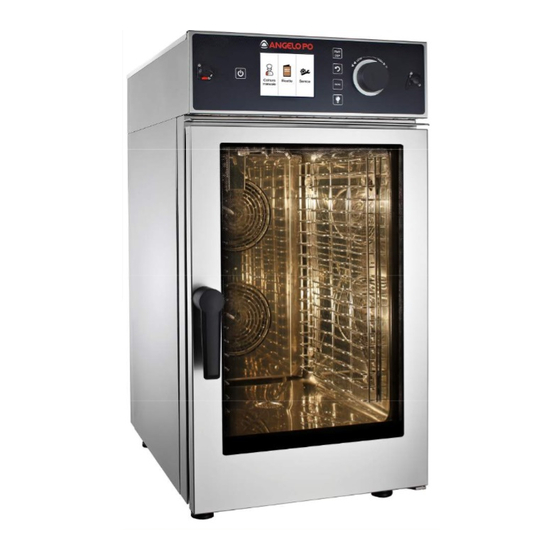
combiFiT
CF623E - CF623ER - CF61E - CF61ER - CF101E - CF101ER
IT - MANUALE DI INSTALLAZIONE,USO E MANUTENZIONE
EN - INSTALLATION, USE AND MAINTENANCE MANUAL
FR - MANUEL D'INSTALLATION, D'UTILISATION ET DE MAINTENANCE
DE - ANLEITUNG ZUR INSTALLATION, GEBRAUCH UND WARTUNG
ES - MANUAL DE INSTALACIÓN, DE USO Y DE MANTENIMIENTO
PT - MANUAL DE INSTALAÇÃO, USO E MANUTENÇÃO
OLA - HANDLEIDING VOOR INSTALLATIE, GEBRUIK EN ONDERHOUDD
ver. 04/2016
Advertisement
Chapters
Table of Contents

Subscribe to Our Youtube Channel
Related Manuals for Angelo Po COMBIFIT CF623E


Summary of Contents for Angelo Po COMBIFIT CF623E
- Page 1 combiFiT CF623E - CF623ER - CF61E - CF61ER - CF101E - CF101ER IT - MANUALE DI INSTALLAZIONE,USO E MANUTENZIONE EN - INSTALLATION, USE AND MAINTENANCE MANUAL FR - MANUEL D’INSTALLATION, D’UTILISATION ET DE MAINTENANCE DE - ANLEITUNG ZUR INSTALLATION, GEBRAUCH UND WARTUNG ES - MANUAL DE INSTALACIÓN, DE USO Y DE MANTENIMIENTO PT - MANUAL DE INSTALAÇÃO, USO E MANUTENÇÃO OLA - HANDLEIDING VOOR INSTALLATIE, GEBRUIK EN ONDERHOUDD...
- Page 3 • IT - MANUALE DI INSTALLAZIONE , USO E MANUTENZIONE combiFiT MOD. FORNI MISTI, A CONVEZIONE E VAPORE CF623E - CF623ER - CF61E - CF61ER - CF101E - CF101ER ver. 04/2016...
-
Page 4: Table Of Contents
Indice 1. Installazione 4.1. Navigazione nel menù ricette 5. Menù service 1.1. Avvertenze generali e di sicurezza 5.1. Lavaggio automatico 1.2. Posizionamento 5.2. Data e ora 1.3. Collegamento idrico 5.3. Regolazione illuminazione camera 1.4. Collegamento dello scarico cottura 1.5. Collegamento elettrico 5.4. -
Page 5: Installazione
1. Installazione 1.1. Avvertenze generali e di sicurezza Leggere attentamente nel presente manuale fa- presente manuale prima ranno decadere la garan- dell’installazione della zia. messa in funzione del for- no, in quanto il testo for- Un’installazione nisce importanti indicazio- manutenzione diverse da ni riguardanti la sicurezza quelle indicate nel libretto d’installazione, d’uso e di possono provocare danni,... - Page 6 la permanenza di persone Prima di eseguire qualun- non addette all’ insallazio- que intervento di instal- ne nei pressi dell’ area di lazione o manutenzione, lavoro. scollegare l’ apparecchio dall’alimentazione elettri- Conservare con cura e in un luogo facilmente acces- sibile questo manuale per Prima di collegare l’appa- ogni ulteriore consultazio-...
- Page 7 L’apparecchio non deve es- ni di esercizio, possono su- sere utilizzato da persone perare anche i 60°C. con ridotte capacità fisiche, sensoriali o mentali o da Pericolo ustioni! persone prive di esperienza Nelle apparecchiature con e conoscenza, a meno che forno, quando la camera di esse non siano supervisio- cottura è...
- Page 8 In caso di prolungato inu- La targhetta matricola for- tilizzo dell’ apparecchiatu- nisce importanti informa- ra, deve essere interrotta zioni tecniche: esse risul- l’erogazione dell’energia tano indispensabili in caso elettrica e, dove previsto, di richiesta di intervento quella dell’ acqua. per una manutenzione o una riparazione dell’...
-
Page 9: Posizionamento
1.2. Posizionamento Gli apparecchi sono stati progettati per essere installati in locali chiusi, non possono essere usati all’aria aperta e non possono essere esposti alla pioggia. Il luogo designato per l’installazione del forno deve presentare una superficie rigida, piana e orizzontale che deve poter sostenere con sicu- rezza sia il peso dell’insieme apparecchio/supporto che quello del carico alla massima capienza. -
Page 10: Collegamento Idrico
1.3. Collegamento idrico pressione dell’acqua deve essere massimo di (600 KPa) 6 bar. Se la pressione dell’acqua della rete di distribuzione fosse superiore a tale valore è necessario installare un riduttore di pressione a monte del forno. pressione minima dell’acqua corretto funzionamento del forno deve essere superiore a 3 bar. -
Page 11: Collegamento Elettrico
Verificare che il sifone interno sia pieno di acqua e, in caso contrario, riempirlo im- mettendo acqua attraverso lo scarico pre- sente in camera di cottura. 1.5. Collegamento elettrico L’impianto elettrico, come prescritto e specificato nella normativa in vigore, deve essere dotato di un’efficiente messa a terra. È... - Page 12 tab. 1 230V 3 230V 2 50/60Hz 50/60Hz 400V 3N 230V 50/60 50/60Hz 208V 3 208V 2 50/60Hz 50/60Hz 3x2,5mm2 5x1.5 CF623E 3x2.5 mm2 3x12 AWG 4x2,5mm2 5x2.5 CF61E 3x6 mm2 4x12 AWG 4x6mm2 CF101E 4x8 AWG COMBIFIT manuale di installazione, uso e manutenzione...
-
Page 13: Messa In Funzione E Collaudo Del Forno
Per effettuare il collegamento elettrico fare riferimento agli schemi elettrici presenti in appendice al presente manuale. Infilare il cavo di alimentazione nel foro del pressacavo che si trova nella parte inferiore, alla sinistra del forno. Collegare il cavo alla morsettiera seguendo le indicazioni riportate in tab. 1. -
Page 14: Istruzioni D'uso
Verificare scrupolosamente i punti dell’elenco seguente: Le luci nella camera di cottura premendo l’apposito tasto T5 (fig. 9) si accendono e dopo 45 secondi, se non spente prima premendo nuovamente il tasto, si spengono automaticamente. Il forno si arresta se viene aperta la porta e riprende a funzionare quando la porta viene richiusa. -
Page 15: Informazioni Preliminari
T2: TASTO START/STOP permette di avviare e arrestare la cottura. Questo tasto può esse- la cottura è in corso; cceso la cottura non è in corso o è stata arrestata; pento la cottura è in stato di attesa (porta aperta, mes- AmpeggiAnte saggi di errori o conferma di operazioni). -
Page 16: Menù Iniziale
La durata dell’illuminazione della camera di cottura varia a seconda dell’impostazione scelta (vedi par. 5.3. pag. 29). L’apertura della por- ta del forno causa il temporaneo spegnimento dell’illuminazione; alla richiusura della porta le luci tornano ad accendersi. Il tasto T2 Start/Stop può alternativamente far iniziare un ciclo di cottura o farne terminare uno già... -
Page 17: Programmazione Manuale
3. Programmazione manuale 3.1. Scelta della modalità di cottura Una volta entrati nella programma- Dom 02-10-15 20:32 zione manuale si può procedere alla Manuale definizione dei parametri di cottura, Fase 1/ 4 quali: modo cottura, ventilazione, 180° tempo, umidità, ecc.. Con una pressione sull’icona S1 ap- 1:20 parirà... - Page 18 MODALITà VAPORE: In questa modalità sarà possibile Dom 02-10-15 20:32 impostare: Pasta al forno • temperatura di cottura tra 50 e Fase 1/ 1 120°C (forni CF..) 100° • il timer da 1 a 120’ o infinito • temperatura della sonda al cuore •...
-
Page 19: Impostazione Del Tempo
3.3. Impostazione del tempo Per impostare il tempo di cottura di ogni singola fase (parte del pro- gramma), selezionare mediante pressione, il display S4 (fig. 18). Im- postare il tempo ruotando la manopola M in senso orario per aumentare il tempo o in senso antiorario per diminuirlo. La conferma dell’impostazione Dom 02-10-15 20:32... -
Page 20: Regolazione Manuale Valvola A Farfalla
3.5. Regolazione manuale della valvola a farfalla In modalità CONVEZIONE sele- Dom 02-10-15 20:32 zionare la posizione della valvola Manuale a farfalla mediante la pressione Fase 1/ 4 dell’icona sullo schermo touch 180° (S6 - fig. 20). Le posizioni pos- sono essere: 1:20 Valvola aperta HEAT Valvola chiusa fig. 20 La valvola ha la funzione di mantenere o far uscire l’umidità... -
Page 21: La Funzione Steam Tuner
3.8. La funzione steam tuner In modalità cottura a VAPO- RE è possibile agire sul controllo Dom 02-10-15 20:32 steam tuner (S9 - fig. 23). Pasta al forno Fase 1/ 1 Il selettore in posizione centrale indica la regolazione media 100° dell’idratazione del vapore. E’ possibile regolare qualità del vapore immesso in camera premendo di tasti + o - in funzione del tipo di cottura desiderata. -
Page 22: Utilizzo Delle Cotture Δt
Impostare la temperatura desiderata ruotando la manopola M dell’encoder in senso orario crescente; confermare la selezione premendo la manopola M. Come posizionare la sonda Dom 02-10-15 20:32 al cuore: Prosciutto Fase 1/ 1 La punta dello spillone va infilata 25° al centro della parte più grossa dell’... - Page 23 Impostare i valori di timer o temperatura sonda al cuore sul livello desiderato selezionando il relativo livello. Apparirà un pop-up dal quale sarà possibile selezionare la modalità timer (a) o sonda al cuore (b). Selezionare la modalità desiderata, e impostare il valore ruotando la manopola M.
-
Page 24: Mantenimento
Nota: quando un livello è completato ed appare la scritta relativo livello il forno non andrà in modalità Stop ma continuerà con la cottura impostata. Per uscire dalla modalità RaCk COnTROl premere per 3 secon- di il tasto S15 fig. 29. Nota: non è possibile memoriz- zare i valori dei vari livelli in mo- 0:01 230°... -
Page 25: Raffreddamento Automatico
3.12. Raffreddamento automatico in cottura Il RaFFREDDaMEnTO auTOMaTICO in cottura consente di imposta- re una fase di raffreddamento della camera del forno tra due fasi di un programma di cottura (vedi paragrafo 3.14 pag. 24), ad esempio tra una fase di rosolatura ed una di cottura a bassa temperatura. Nota: l’icona del raffreddamento automatico (rif. -
Page 26: Raffreddamento Manuale
3.13. Raffreddamento manuale camera di cottura La funzione raffreddamento permette all’operatore di far scendere ra- pidamente la temperatura in camera di cottura. Per eseguire un ciclo di raffred- Dom 02-10-15 20:32 damento camera di cottura il for- no deve essere in modalità Stop. Raffreddamento Fase 1 / 1 Selezionare il tasto raffredda- mento (S19 fig. -
Page 27: Memorizzazione E Gestione Delle Ricette
3.15. Memorizzazione e gestione delle ricette È possibile salvare il programma di cottura creato all’interno del ricet- tario elettronico del forno. Una volta terminata la creazio- ne di un programma di cottura, Dom 02-10-15 20:32 premere il tasto S21 fig. 36 Manuale Fase 2 / 2 per accedere alla pagina gestione ricette (fig. 37). -
Page 28: Menù Ricette
4. Menù Ricette 4.1. Navigazione nel menù ricette Il menù ricette permette di accedere ai programmi di cottura e salvati nella memoria del forno. Dalla schermata principale selezionare il menù ricette. Selezionare il gruppo (fig. 40) di riferimento (ad esempio carne se si vuole cucinare un arrosto) e successivamente scegliere il pro- gramma desiderato ruotando in senso orario la manopola per po-... -
Page 29: Menù Service
5. Menù Service 5.1. Lavaggio automatico Nei forni dotati di lavaggio automatico è possibile accedere a tale fun- zione entrando dal menù principale nel menù Service. Selezionare la voce lavaggio dal menù premendo la manopola M. Selezionare quindi il tipo di la- Funzioni servizio vaggio automatico (fig. 42) in base al grado di sporco all’inter- Lavaggio... -
Page 30: Data E Ora
Nota: nel caso la temperatura della camera sia superiore ai 150°C il forno proporrà automaticamente il raffreddamento della camera di cot- tura (vedi paragrafo 3.13 pag. 24). Eseguire il raffreddamento e poi riavviare il lavaggio. IMPORTANTE: Utilizzare il detergente fornito dal costruttore del forno per ot- tenere il massimo risultato. La composizione chimica del deter- gente è: potassa caustica con concentrazione inferiore al 20%. L’uso di prodotti con composizione diversa può danneggiare l’impianto e le pareti del forno; i residui rilasciati possono con- taminare i cibi. -
Page 31: Cottura
5.3. Regolazione della durata dell’illuminazione in camera di cottura È possibile regolare la dura- Funzioni servizio ta dell’illuminazione in camera di cottura attraverso la voce para- metri nel menù Service. Lavaggio Premere prima la manopola sulla voce parametri e poi confermare Data e ora (senza aver impostato alcuna pas- Parametri... -
Page 32: Lingua
5.5. Lingua Funzioni servizio Mediante la funzione lingua è possibile cambiare la lingua del menù del forno. Data e ora Parametri Retroilluminazione Info Sistema Lingua fig. 49 5.6. Servizi avanzati Funzioni servizio La funzione Servizi avanzati (fig. 50), protetta da password numerica selezionabile tramite la Parametri manopola M, consente di accede- Retroilluminazione... -
Page 33: Importa/Esporta Ricette
5.8. Importa/Esporta ricette Inserendo una chiavetta nella porta USB posta sul pannello comandi (fig. 51) si attivano le funzioni di importazione ed esportazione delle ricette. La funzione Importa ricette Funzioni servizio (fig. 52), permette di caricare nella memoria del forno le ricet- te precedentemente impostate su Info Sistema PC o esportate da un altro forno. -
Page 34: Manutenzione
6. Manutenzione 6.1. Pulizia Prima di eseguire qualsiasi intervento di pulizia o manutenzione scol- legare l’ apparecchiatura dall’ alimentazione elettrica. Alla fine di una giornata di lavoro, è necessario pulire l’apparecchiatura, sia per motivi d’igiene che per evitare guasti di funzionamento. Il forno non deve mai essere pulito con getti d’acqua diretti o ad alta pressione. -
Page 35: Scarico Umidità
6.3. Scarico umidità Lo scarico umidità (rif. B fig. 53 pag. 32) espelle i vapori prodotti all’interno della camera di cottura. Controllare che esso sia sempre pulito e perfettamente libero da ostru- zioni. 6.4. Pulizia del vetro La pulizia del vetro della porta può essere effet- tuata sia sul lato esterno che su quello interno. -
Page 36: Componenti Di Controllo E Sicurezza
7. Componenti di controllo e sicurezza 7.1. Microinterruttore porta Il microinterruttore porta è il dispositivo che interrompe il ciclo di cottura del forno al momento dell’apertura della porta. Alla successiva chiusura della porta il ciclo interrotto riprende normalmente. Non azionare questo dispositivo manualmente con la porta del forno aperta. -
Page 37: Cosa Fare Se
8. Cosa fare se.. 8.1. Problemi più comuni Qualora si verificasse un’anomalia grave è importantissimo spegnere l’apparecchiatura, agendo sull’interruttore onnipolare, e chiudere il rubinetto d’intercettazione dell’acqua posto a monte dell’apparecchio. Problema Possibile soluzione Controllare che l’interruttore onnipolare sia chiuso e che sia presente la tensione di rete. Verificare l’integrità... -
Page 38: Controlli (Per Tecnico Specializzato)
8.2. Controlli eseguibili solo da un tecnico autorizzato Togliere l’alimentazione elettrica prima di compiere qualsiasi regola- zione o intervento. Riarmo del termostato di sicurezza Il termostato di sicurezza è collocato sulla parte posteriore del forno in alto (fig. 58). Individuare il termostato, e premere il pulsante rosso fino a quando si avverte un rumore meccanico (“clic”) che confermerà... -
Page 39: Dismissione Apparecchiatura
9. Dismissione apparecchiatura In fase di dismissione, è necessario effettuare una serie di interventi per fare in modo che l’apparecchiatura ed i suoi componenti non costi- tuiscano un intralcio e non siano facilmente accessibili. Per evitare che l’apparecchiatura possa costituire pericoli per le perso- ne e l’ambiente, è... -
Page 40: Descrizione Allarmi
10. Descrizione allarmi In caso di allarme sul display temperatura e sul display tempo compa- re il nome identificativo dell’allarme in corso. Sono gestiti i seguenti allarmi: Nome Descrizione Azioni SOLUZIONE Sonda Errore sonda Blocco Sostituire la sonda camera. camera camera cottura, ripristino automatico. - Page 41 11. Schede tecniche 11.1. CF623E 4,4 kW G3/4” Ø 40 G3/4” Ø 40 4,4 kW COMBIFIT manuale di installazione, uso e manutenzione...
- Page 42 11.2. CF61E 6,6 kW G3/4” Ø 40 G3/4” Ø 40 6,6 kW COMBIFIT manuale di installazione, uso e manutenzione...
- Page 43 11.3. CF101E 13,2 kW 1036 G3/4” Ø 40 G3/4” Ø 40 13,2 kW COMBIFIT manuale di installazione, uso e manutenzione...
-
Page 44: Schemi Elettrici
12. Schemi elettrici 12.1. CF623E COMBIFIT manuale di installazione, uso e manutenzione... - Page 45 12.2. CF61E COMBIFIT manuale di installazione, uso e manutenzione...
- Page 46 12.3. CF101E COMBIFIT manuale di installazione, uso e manutenzione...
- Page 47 SCHEMI ELETTRICI LEGENDA C,C1,,, Condensatore EU,EU1,EU2 Elettrovalvola umidifi catore Elettrovalvola abbattimento vapore (condensazione) Elettrovalvola lavaggio Elettrovalvola detergente Elettrovalvola bruciatore camera FM1,FM2 Protezione termica motore (incorporata.) FU1,FU2… Fusibile Filtro E.M.C. di linea FR1,FR2… Motoventilatori di raffreddamento Termostato sicurezza camera Inverter motore Relé...
- Page 48 Acqua: requisiti della fornitura di acqua IMPORTANTE: L’apparecchiatura deve essere alimentata con acqua potabile con le caratteristiche indicate in tabella. Parametri da verificare Valore Pressione 200÷400 kPa (2÷ 4 bar) (*) Portata acqua (l/h) 9 l/h (CF61E) (*) 7÷8.5 40÷150 ppm Durezza 3.9°f (1,5÷5°d, 2.1÷6.3°e, 30÷90 ppm) Indice di Langelier (raccomandato) (**) >0.5 Contenuto di sali e ioni metallici...
- Page 49 IMPORTANTE: In caso di uso di sostanze chimiche nel sistema di fornitura dell’acqua per la sanificazione, come clorammine o ipoclorito di sodio, è necessario installare un filtro per garantire la loro rimozione. Verificare la presenza di parti corrose nei tubi e nei raccordi, poiché potrebbero contaminare l’acqua all’interno dell’apparecchio.
- Page 51 • EN - INSTALLATION, USE AND MAINTENANCE MANUAL combiFiT MOD. MIxED CONVECTION/STEAM OVENS CF623E - CF623ER - CF61E - CF61ER - CF101E - CF101ER ver. 04/2016...
- Page 52 Contents How to navigate through the recipe 4.1. menu 1. Installation 5. Service menu 5.1. Self-cleaning 1.1. General safety warnings 5.2. Date and time 1.2. Positioning 5.3. Cooking chamber lighting 1.3. Water connection 5.4. System info 1.4. Drain pipe connection 5.5. Language 1.5.
-
Page 53: Installation
1. Installation General safety warnings 1.1. Please read this manual carefully before installating and commissioning the oven, because it provides important information about the safe installation, use and mainte- nance of the appliance. Keep the manual in a location that can be easily accessed by the operators for further consultation. - Page 54 The oven should not be used by persons with reduced physical, sensorial or mental capabilities or lack of ex- perience and knowledge, unless they are supervised or trained on how to use the appliance by a person respon- sible for their safety. The appliance must be placed in a suitably ventilated room to prevent harmful the excessive accumulation of harmful substances in the air.
- Page 55 sary should be approved and carried out by authorized technical staff. The appliance is intended to be used exclusively for pro- fessional use, by qualified staff It is strictly forbidden to carry out any kind of modifica- tions to oven wiring. Failure to comply with the above instructions can compro- mise the safety of the equipment and yours, too.
-
Page 56: Positioning
1.2. Positioning The appliances have been designed to be installed indoors and cannot be used outdoors neither be exposed to rain. The location designated for oven installation shoult have a solid, flat and horizontal surface, able to safely support both the weight of the appliance-support group and that the maximum rated load. -
Page 57: Water Connection
The oven should be levelled: to ad- just the height of the leveling feet proceed as shown in fig. 2, using a spirit level. Unevenness or inclinations of a certain degree can compromise the operation of the oven. Remove the entire protective film from the external panels of the ap- pliance, detaching it slowly to re- move all traces of adhesive. - Page 58 Before connection, drain off a sufficient amount of water to clean the pipe from metal residues. Connect the “Water” pipeline to water mains and install a shut-off valve and a filter on the pipe. Ensure that the shut-off valve is positioned so that it can be easily operted by the operator at any time.
- Page 59 1.5. Electrical connection The electrical system shall be fitted with an efficient earthing system, as required by the regulations in force. You can ensure the electrical safety of the appliance only in the presence of a compliant electrical system. Before wiring, check the voltage and frequency of the power grid to ensure that they comply with appliance rated values given on the technical data plate (fig. 6).
- Page 60 tab. 1 230V 3 230V 2 50/60Hz 50/60Hz 400V 3N 230V 50/60 50/60Hz 208V 3 208V 2 50/60Hz 50/60Hz 3x2,5mm2 5x1.5 CF623E 3x2.5 mm2 3x12 AWG 4x2,5mm2 5x2.5 CF61E 3x6 mm2 4x12 AWG 4x6mm2 CF101E 4x8 AWG COMBIFIT installation, use and maintenance manual...
-
Page 61: Oven Commissioning And Testing
Secure the cable with the cable gland. The feed voltage, when the machine is operating, should not vary in relation to the rated voltage by more than ± 10%. The applinace must be included into an equipotential system whose efficency is checked in compliance with the standards in force. -
Page 62: Instructions For Use
door is closed. The thermostat that regulates the temperature in the cooking chamber is triggered when the set temperature is reached and the heating element is shut off temporarily. The fan motor reverses the direction of rotation automatically; reversal takes place every 3 minutes (time varies depending on the cooking time). -
Page 63: Preliminary Information
T2: START/STOP KEY it enables starting and stopping the cooking cycle. This key can cooking in progress; cooking not in progress or stopped; cooking is in waiting state (door open, error LAshing messages or confirmation of operations). T3: ESC KEY: it allows the user to return to the previous page. T4: MENU KEY: it enables the user to return to the main menu. -
Page 64: Main Menu
lighting system shuts down temporarily; when the door is closed, the lights turn on again. The T2 Start/Stop key can either start a cooking cycle or end a cook- ing cycle in progress. If the cooking cycle is interrupted prematurely using the key T2, no sound warning is generated. This key also silences the cooking cycle end signal. -
Page 65: Manual Setup
3. Manual setup 3.1. Cooking mode selection Once you have accessed the man- Dom 02-10-15 20:32 ual setup you can start defining the Manuale Fase 1/ 4 cooking parameters such as: cooking mode, ventilation, time, moisture, 180° etc. 1:20 By pressing the icon S1 once, a pop- up window will be displayed (fig. 12) showing the cooking modes available: HEAT... - Page 66 STEAM MODE: In this mode it is possible to set: Dom 02-10-15 20:32 cooking temperature Pasta al forno • Fase 1/ 1 tween 50 and 120°C (ovens CF..) 100° the timer from 1 to 120’ or infi- • nite core probe temperature •...
-
Page 67: Time Settting
3.3. Time setting To set the cooking time of each single stage (part of the program), select it by pressing the display S4. Set the time turning the dial M clockwise to increase the time or counterclockwise to decrease it. Confirm the set value by presisng the key S4 again or by pressing Dom 02-10-15 20:32... - Page 68 3.5. Manual adjustment of the throttle valve In CONVECTION mode, select Dom 02-10-15 20:32 the position of the throttle valve Manuale by pressing on the icon on the Fase 1/ 4 touch screen (S6 - fig. 20). The 180° positions can be: 1:20 Valve open Valve closed HEAT fig. 20 The valve has the task of maintaning or expelling the moisture outside the oven.
-
Page 69: Steam Tuner Function
3.8. The steamtuner function In STEAM cooking mode, it is Dom 02-10-15 20:32 possible to operate the steam tuner control (S9 - fig. 23). Pasta al forno Fase 1/ 1 The selector in middle position 100° indicates the average adjustment of steam hydration. The quality of the steam inroduced inside the cooking chamber can be adjusted by pressing keys.+ or -, depending on the type of cooking... -
Page 70: Using Δt Cooking Modes
Set the desired temperature by turning the dial M of the encoder clockwise; confirm the selection by pressing the dial M. How to position the probe to Dom 02-10-15 20:32 the core: Prosciutto Fase 1/ 1 The probe should be placed in 25° the food so that the tip is located in the center of the thickest part 55°... - Page 71 Set the timer or core probe temperature to the desired level by select- ing the relative level. A pop-up will be displayed, enabling you to select the timer (a) or core probe (b) mode. Select the desired mode, and set the value by turning the dial M.
-
Page 72: Maintenance
the set cooking cycle. To exit the RaCk COnTROl mode, press the key S15 fig. 29 for 3 seconds. Note: the values of the various levels in RaCk COnTROl mode cannot be memorized; however, in the case you exit this mod- ule by accident, you can access 0:01 it again (without changing the 230°... -
Page 73: Automatic Cooling
3.12. Automatic cooling during cooking The auTOMaTIC COOlIng during cooking enables setting a cooling phase inside the cooking chamber between two phases of the cooking program (see section 3.14 pag. 24), for example, between a browning and a low-temperature cooking phase. Note: the automatic cooking icon (ref. and fig. 32) is visible only from phase 2. -
Page 74: Manual Cooling
3.13. Manual cooling of the cooking chamber The cooling function allows the operator to quickly reduce the tem- perature in the cooking chamber. To run a cooling cycle in the Dom 02-10-15 20:32 cooking chamber, the oven shoud Raffreddamento be set to Stop mode. Select the Fase 1 / 1 cooling key (S19 fig. -
Page 75: Memorizing And Managing The Recipes
3.15. Memorizing and managing the recipes The cooking program created inside the electronic recipe book of the oven can be saved. Once you have finished creat- Dom 02-10-15 20:32 ing a cooking program, press the key S21 fig. 36 to access the Manuale Fase 2 / 2 recipe management page (fig. -
Page 76: Recipe Menu
4. Recipe Menu 4.1. How to navigate through the recipe menu The recipe menu gives you access to the cooking programs stored in the memory of the oven. Select the recipe menu from the main page. Select the reference group (fig. 40), for example meat, if you wish to make a roast, and then choose desired program... -
Page 77: Service Menu
5. Service Menu 5.1. Self-cleaning The self-cleaning function of the ovens equipped with this function can be accessed by entering the Service menu from the main menu. Service function Select cleaning option from the menu by pressing the dial M. Cleaning Date and time Now select the type of self- cleaning (fig. 42) based on how Parameters... - Page 78 HAZARD: Do not open the door of the oven during cleaning. IMPORTANT: The cleaning nozzle should be cleaned periodically in a dish- washer. Loosen the screws A and remove the nozzle, pulling it downwards. After cleaning, re-insert the nozzle into its slot by pushing it upwards and tighten the screw A. fig. 44 5.2. Date and time The Date and time functions enables adjusting the time and date on...
-
Page 79: System Info
5.3. Adjust the duration of lighting in the cooking chamber YOU can adjust the duration of lighting in the cooking chamber Service function using the option parameters in Service menu. Washing Press the dial on the option pa- rameters first and then confirm Date and time (without having set any password) by pressing the dial. -
Page 80: Language
5.5. Language Service function Using this function it is possible to change the language of oven’s menu. Date and time Parameters Backlight System Info Language fig. 49 Service function 5.6. Advanced services The Advanced services (fig. 50) function, protected by nu- Parameters merical and selectable via m dial, provides access to test functions Backlight reserved to qualified technical... -
Page 81: Import/Export Recipes
5.8. Import/Export recipes Insert a flash drive in the USB port located on the control panel (fig. 59) to activate the recipe import /export functions. Service function The Import recipe (fig. 52) function enables loading in oben’s memory the recipes previously set on PC or exported from an- System Info other oven. -
Page 82: Maintenance
6. Maintenance 6.1. Cleaning At the end of the working day, clean the appliance, both for reasons of hygiene and to prevent operating faults. The oven should never be cleaned with direct water or high pressure jets. Moreover, the appliance should not be cleaned with wire sponges, ordinary steel brushes or scrapers;... -
Page 83: Moisture Drain
6.3. Moisture drain Moisture drain (ref. B fig. 53 page 32) ejects the vapors produced inside the cooking chamber. Check that it is always perfectly clean and free from obstructions. 6.4. Cleaning glass The door window can be cleaned either on the outside and on the inside. Turn the latch that locks the internal window (fig. 54) ande, once you have opened the window, clean it with a suitable deter- gent. -
Page 84: Control And Safety Devices
7. Control and safety devices 7.1. Door micro switch The door microswitch is the device which stops the cooking cycle of the oven when the door is opened. Once te door is closed, the regular cycle is resumed. Do not operate this device manually with the oven door open. 7.2. Motor thermal breaker The fan motor is equipped with a built-in thermal protection which stops operation in case of overheating. -
Page 85: Troubleshooting
8. Troubleshooting 8.1. Common problems In the event of severe failure, it is essential to turn off the appliance, operating the omnipolar circuit breaker, and close the water shut-off valve located upstream of the appliance. Problema Possible solution Check that the omnipolar circuit breaker is closed and the grid voltage is present. -
Page 86: Checks (For Qualified Technician)
8.2. Checks that can only be performed by an authorized technician Cut off the power supply before proceeding with any adjustment or intervention. Safety thermostat reset The safety thermostat is placed on the rear upper side of the oven (fig. 58). Locate the thermostat, and press the red button until you hear a mechanical warn- ing sound (“click”) that will confirm the closure of the contacts (fig. 58). -
Page 87: Decommissioning The Appliance
9. Decommissioning the appliance When decommissioning the appliance, a series of procedures must be carried out to ensure that the appliance and its components are not a hindrance and are not easily accessible. To ensure that the appliance cannot constitute hazards for people or the environment, all energy sources (electricity, etc.) must be discon- nected and rendered unusable, and any liquids present must be drained (lubricants, fluids, etc.). -
Page 88: Alarms Description
10. Alarms description If an alarm is triggered, on temperature and time display is shown the name of the alarm triggered. The alarms managed are the following Name Description Actions SOLUTION Chamber Chamber probe Cooking Replace the chamber probe. probe failure cycle block; automatic reset. - Page 89 11. Technical Data Sheets 11.1. CF623E 4,4 kW G3/4” Ø 40 G3/4” Ø 40 4,4 kW COMBIFIT installation, use and maintenance manual...
- Page 90 11.2. CF61E 6,6 kW G3/4” Ø 40 G3/4” Ø 40 6,6 kW COMBIFIT installation, use and maintenance manual...
-
Page 91: Cf101E
11.3. CF101E 13,2 kW 1036 G3/4” Ø 40 G3/4” Ø 40 13,2 kW COMBIFIT installation, use and maintenance manual... - Page 92 12. Wiring diagrams 12.1. CF623E COMBIFIT installation, use and maintenance manual...
- Page 93 12.2. CF61E COMBIFIT installation, use and maintenance manual...
- Page 94 12.3. CF101E COMBIFIT installation, use and maintenance manual...
- Page 95 ELECTRICAL DIAGRAMS LEGEND C,C1,,, Condenser EU,EU1,EU2 Humidifi er solenoid Steam (condensation) chiller solenoid Wash solenoid Elettrovalvola detergente Chamber burner solenoid FM1,FM2 Motor thermal protection (built-in) FU1,FU2… Fuse EMC line fi lter FR1,FR2… Cooling fan motor Chamber safety thermostat Motor inverter Inverter line relay Power line auxiliary contactor Keyboard...
- Page 96 Water: requirements for supplied water IMPORTANT: The appliance must be supplied with drinking water having the char- acteristics shown in the table. Parameters to be checked Value Pressure 200÷400 kPa (2÷ 4 bar) (*) Water flow rate (l/h) 9 l/h (CF61E) (*) 7÷8.5 40÷150 ppm Hardness 3.9°f (1,5÷5°d, 2.1÷6.3°e, 30÷90 ppm) Langelier index ( Recommended) (**)
- Page 97 IMPORTANT: Wherever chemicals are used in the water supply system for water sanification, for example chloramines or sodium hypochlorite, it is nec- essary to install a filter to guarantee their removal. Check water pipes and fittings for corroded parts, they may pollute the water inside the appliance.
- Page 99 • FR - MANUEL D’INSTALLATION, D’UTILISATION ET DE MAINTENANCE combiFiT MOD. FOURS MIxTES à CONVECTION ET à VAPEUR CF623E - CF623ER - CF61E - CF61ER - CF101E - CF101ER ver. 04/2016...
- Page 100 Table des matières 5. Menu service 5.1. Lavage automatique 1. Installation 5.2. Date et heure 1.1. Avertissements généraux et de sécurité 5.3. éclairage de la chambre de cuisson 5.4. Informations système 1.2. Positionnement 5.5. Langue 1.3. Raccordement hydraulique 5.6. Services améliorés 1.4. Raccordement de l’évacuation 5.7.
-
Page 101: Installation
1. Installation 1.1. Mises en garde générales et de sécurité Lire attentivement ce manuel avant l’installation et la mise en fonction du four car ce texte fournit des indications im- portantes concernant la sécurité de l’installation, de l’uti- lisation et de la maintenance de l’appareil. Conserver soigneusement ce manuel dans un lieu faci- lement accessible pour permettre aux opérateurs de le consulter. - Page 102 dommages causés à l’appareil il est en outre fondamen- tal que le personnel reçoive régulièrement les instructions précises concernant la sécurité. Le four ne doit pas être utilisé par des personnes ayant des capacités physiques, sensorielles ou mentales réduites ou bien par des personnes sans expérience ni connaissance, à...
- Page 103 Toute modification apportée à l’installation du four qui de- vrait s’imposer devra être approuvée et effectuée par un personnel technique autorisé. L’appareil est destiné à une utilisation uniquement profes- sionnelle et par un personnel qualifié Aucun type de modification n’est admis au câblage du four. Le non-respect des mises en garde précédentes peut com- promettre la sécurité...
-
Page 104: Positionnement
1.2. Positionnement Les appareils ont été conçus pour être installés dans des milieux clos, ils ne peuvent pas être utilisés à l’extérieur et ils ne peuvent pas être exposés à la pluie. Le lieu désigné pour l’installation du four doit avoir une surface ri- gide, plate et horizontale capable de soutenir en toute sécurité... - Page 105 Le four doit être mis sur un plan: pour régler la hauteur des pieds de nivellement on agit, à l’aide d’un niveau à bulle d’air, comme indiqué dans la fig. 2. Des dénivellements ou des incli- naisons considérables peuvent in- fluencer négativement le fonction- nement du four.
-
Page 106: Raccordement De L'évacuation
Avant le raccordement, laisser s’écouler quantité d’eau suffisante pour nettoyer canalisation des éventuels résidus ferreux. Raccorder la canalisation «Eau» au réseau de distribution de l’eau froide spécifique et interposer un robinet d’arrêt et un filtre. En s’assurant que le robinet d’arrêt soit positionné... -
Page 107: Branchement Électrique
1.5. Branchement électrique L’installation électrique, comme prescrit et spécifié par la réglementation en vigueur, doit être dotée d’une mise à la terre efficace. La sécurité électrique de l’appareil peut être garantie uniquement si l’installation électrique est aux normes. Avant d’effectuer le branchement électrique, ils faut contrôler à ce que les valeurs de tension et de fréquence du réseau électrique soient conformes aux standards de l’appareil indiqués sur la plaquette technique (fig. 6). - Page 108 tab. 1 230V 3 230V 2 50/60Hz 50/60Hz 400V 3N 230V 50/60 50/60Hz 208V 3 208V 2 50/60Hz 50/60Hz 3x2,5mm2 5x1.5 CF623E 3x2.5 mm2 3x12 AWG 4x2,5mm2 5x2.5 CF61E 3x6 mm2 4x12 AWG 4x6mm2 CF101E 4x8 AWG COMBIFIT manuel d’installation, d’utilisation et de maintenance...
-
Page 109: Mise En Fonction Et Essai Du Four
dans la partie inférieure à la gauche du four. Brancher le câble au bornier en suivant les indications qui figurent dans le tab. 1. Pour effectuer le branchement électrique se référer aux sché- mas électriques présents en supplément au présent manuel. Introduire le câble d’alimentation dans le trou du presse- étoupe qui se trouve dans la partie inférieure à... -
Page 110: Instructions D'utilisation
Configurer un cycle de cuisson à une température de 150º C, temps 10 min et humidité à 25%. Appuyer sur la touche T2 (fig. 9) “Start/Stop”. Vérifier scrupuleusement les points de la liste suivante: Les lumières dans la chambre de cuisson s’allument en appuyant sur la touche prévue à... -
Page 111: Informations Préliminaires
T2: TOUCHE START/STOP permet de lancer et arrêter la cuisson. Cette touche peut être: la cuisson est en cours; LLumée é la cuisson n’est pas en cours ou elle a été arrêtée; teinte la cuisson est en état d’attente (porte ouverte, LignotAnte messages d’erreurs ou confirmation d’opérations). -
Page 112: Menu Initial
La durée de l’éclairage de la chambre de cuisson varie en fonction de la configuration choisie (voir par. 5.3. page 29). L’ouverture de la porte du four cause l’éteignement momentané de l’éclairage; à la fer- meture de la porte les lumières se rallument. La touche T2 Start/Stop peut à... -
Page 113: Programmation Manuelle
3. Programmation manuelle 3.1. Choix de la modalité de cuisson Une fois entrés dans la programma- Dom 02-10-15 20:32 tion manuelle on peut procéder à la Manuale Fase 1/ 4 définition des paramètres de cuisson, tels que: mode de cuisson, ventila- 180° tion, temps, humidité, etc. En appuyant sur l’icône S1 un pop- 1:20 up apparaîtra (fig. 12) avec les mo- des de cuisson disponibles:... -
Page 114: Préchauffage Automatique Du Four
MODALITÉ VAPEUR: Dans cette modalité il sera possible Dom 02-10-15 20:32 de configurer: Pasta al forno Fase 1/ 1 la température de cuisson entre 50 • et 120°C (fours CF..) 100° le timer de 1 à 120 min. ou infini • température de la sonde au cœur •... -
Page 115: Configuration Du Temps
3.3. Configuration du temps Pour configurer le temps de cuisson de chaque phase (partie du programme) sélectionner à travers la pression sur l’afficheur de S4 (fig. 18). Configurer le temps en tournant la poignée M dans le sens des aiguilles d’une montre pour augmenter le temps ou dans le sens inverse des aiguilles d’une montre pour le diminuer. -
Page 116: Vanne Papillon
3.5. Réglage manuel de la vanne papillon en modalité CONVeCTION sé- Dom 02-10-15 20:32 lectionner la position de la vanne Manuale papillon à travers la pression sur Fase 1/ 4 l’icône de l’afficheur écran-tac- 180° tile (S6 - fig. 20). Les positions peuvent être: 1:20 Vanne ouverte HEAT Vanne fermée fig. 20... -
Page 117: La Fonction Steam Tuner
3.8. La fonction steam tuner En modalité cuisson à VAPEUR Dom 02-10-15 20:32 on peut agir sur le contrôle steam tuner (S9 - fig. 23). Pasta al forno Fase 1/ 1 Le sélecteur en position centrale 100° indique le réglage moyen de l’hydratation de la vapeur. On peut régler la qualité de la vapeur introduite dans la chambre en appuyant sur les touches + ou - en fonction du type de cuisson... -
Page 118: Utilisation Des Cuissons Δt
Configurer la température souhaitée en tournant la poignée M de l’encodeur dans le sens des aiguilles d’une montre croissant; confirmer la sélection en appuyant sur la poignée M. Comment positionner la Dom 02-10-15 20:32 sonde au cœur?: Prosciutto Fase 1/ 1 La sonde à aiguille doit être positionnée en la faisant pénétrer 25°... -
Page 119: La Cuisson
Configurer les valeurs de timer ou de température sonde au cœur sur le niveau souhaité en sélectionnant le niveau relatif. Un pop-up appa- raîtra depuis lequel il sera possible de sélectionner la modalité timer (a) ou la sonde au cœur (b). Sélectionner la modalité souhaitée et confi- gurer la valeur en tournant la poignée M confirmer en appuyant sur la poignée M ou sur le pop-up. -
Page 120: Maintien
Remarque: lorsqu’un niveau est complété et apparaît le message sur le niveau correspondant, le four n’ ira pas en modalité Stop mais continuera avec la cuisson configurée. Pour sortir de la modalité RaCk COnTROl appuyer pendant 3 secondes sur la touche S15 fig. Remarque: on ne peut pas mémoriser les valeurs des di- 0:01... -
Page 121: Refroidissement Automatique
3.12. Refroidissement automatique en cuisson Le REFROIDISSEMEnT auTOMaTIquE en cuisson permet de confi- gurer une phase de refroidissement de la chambre du four entre deux phases d’un programme de cuisson (voir paragraphe 3.14 page 24), par exemple entre une phase de rissolage et une de cuisson à basse température. -
Page 122: Refroidissement Manuel
3.13. Refroidissement manuel de la chambre de cuisson The cooling function allows the operator to quickly reduce the tem- perature in the cooking chamber. La fonction de refroidissement permet à l’opérateur de faire descendre rapidement la température dans Dom 02-10-15 20:32 la chambre de cuisson. Raffreddamento Fase 1 / 1 Pour effectuer un cycle de re- froidissement de la chambre de 180°... -
Page 123: Mémorisation Et Gestion Des Recettes
3.15. Mémorisation et gestion des recettes IL eST possible de sauvegarder le programme de cuisson créé à l’inté- rieur du livre de recette électronique du four. Une fois terminée la création d’un programme de cuisson, ap- Dom 02-10-15 20:32 puyer sur la touche S21 fig. mém Manuale Fase 2 / 2... -
Page 124: Menu Recettes
4. Menu recettes 4.1. Navigation dans le menu recettes Le menu recettes permet d’accéder aux programmes de cuisson sau- vegardés dans la mémoire du four. Depuis la page-écran principale sélectionner le menu recettes. Sélectionner groupe (fig. 40) de référence (par exemple viande si l’on veut cuisiner un rôti) et successivement choisir le programme souhaité... -
Page 125: Menu Service
5. Menu service 5.1. Lavage automatique Dans les fours équipés de lavage automatique on peut accéder à cette fonction en entrant depuis le menu principal dans le menu Service. Sélectionner la voix lavage de- puis le menu en appuyant sur la Fonctions service poignée M. Ensuite sélectionner le type de Lavage lavage automatique (fig. 42) -
Page 126: Date Et Heure
Il faut nettoyer pé- riodiquement dans le lave-vaisselle le diffu- seur du lavage. Dévisser la vis A et ôter le diffuseur en le tirant vers le bas. Après le nettoyage intro- duire à nouveau le diffu- seur dans son logement en le poussant vers le haut et revisser la vis A. -
Page 127: Informations Système
5.3. Réglage de la durée de l’éclairage dans la chambre de cuisson ON peut régler la durée de l’éclai- rage dans la chambre de cuisson à Fonctions service travers la voix paramètres dans le menu Service. Lavage Appuyer d’abord la poignée sur la voix paramètres et ensuite confirmer (sans avoir configuré Date et heure aucun mot de passe) en appuyant sur la poignée. -
Page 128: Langue
5.5. Langue Fonctions service Grâce à la fonction «langue» on peut changer la langue du menu du four. Date et heure Paramètres Rétroéclairage Informations du système Langue fig. 49 5.6. Services améliorés Fonctions service La fonction Services améliorés (fig. 50), protégée par un mot de Paramètres passe numérique sélectionnable à... -
Page 129: Importation/Exportations Des Recettes
5.8. Importation/exportations des recettes En introduisant une clé dans la porte USB située sur le panneau des commandes (fig. 51) les fonctions d’importation et d’exportation des recettes s’activent. La fonction Importation des Fonctions service recettes (fig. 52), permet de télécharger dans la mémoire du four les recettes précédemment Informations du système configurées sur PC ou exportées... -
Page 130: Maintenance
6. Maintenance 6.1. Nettoyage À la fin d’une journée de travail, il faut nettoyer l’appareil, aussi bien pour des raisons d’hygiène que pour éviter des pannes de fonctionnement. Le four ne doit jamais être nettoyé avec des jets d’eau directs ou à haute pression. -
Page 131: Évacuation De L'humidité
6.3. Évacuation de l’humidité L’évacuation de l’humidité (réf. B fig. 53 page 32) élimine les vapeurs produites à l’intérieur de la chambre de cuisson. Contrôler qu’il soit toujours propre et parfaitement dégagé des obs- tructions. 6.4. Nettoyage de la vitre Le nettoyage de la vitre de la porte peut être ef- fectué... -
Page 132: Composants De Contrôle Et De Sécurité
7. Composants de contrôle et de sécurité 7.1. Micro-interrupteur de la porte Le micro-interrupteur de la porte est le dispositif qui interrompt le cycle de cuisson du four au moment de l’ouverture de la porte. À la fermeture successive de la porte le cycle interrompu reprend normalement. Ne pas actionner ce dispositif manuellement avec la porte du four ouverte. -
Page 133: Que Faire Si
8. Que faire si ? 8.1. Les problèmes plus fréquents Si une anomalie grave devrait se vérifier il est très important d’arrêter l’appareil, en agissant sur l’interrupteur omnipolaire et fermer le robinet d’arrêt de l’eau situé en amont de l’appareil. Problème Solution possible Contrôler que l'interrupteur omnipolaire soit fermé et que la tension de réseau soit présente. -
Page 134: Gestion Des Pièces De Rechange
8.2. Contrôles pouvant être effectués uniquement par un technicien autorisé Couper l’alimentation électrique avant d’effectuer tout réglage ou intervention. Réarmement du thermostat de sécurité Le thermostat de sécurité est placé sur la partie postérieure du four en haut (fig. 58). Localiser le thermostat et appuyer sur le bouton rouge jusqu’à l’avertissement d’un bruit mécanique (“clic”) qui confirmera la fermeture des contacts advenue (fig. 58). -
Page 135: Élimination De L'appareil
9. Élimination de l’appareil Au moment de l’élimination, il faut effectuer une série d’opérations pour faire en sorte que l’appareil et ses composants ne constituent pas une gêne et ne soient pas facilement accessibles. Pour éviter que l’appareil puisse constituer un danger pour les person- nes et l’environnement, il faut débrancher et rendre inutilisables toutes les sources d’alimentation (électrique, etc.) et vider tous les liquides éventuellement présents (lubrifiants, huiles, etc.). -
Page 136: Description Des Alarmes
10. Description des alarmes en cas d’alarme sur l’afficheur de la température et sur l’afficheur du temps apparaît le nom d’identification de l’alarme en cours. Les alarmes suivante sont gérées Description Actions SOLUTION Sonde Erreur sonde Blocage de Remplacer la sonde chambre. chambre chambre la cuisson, rétablissement... -
Page 137: Fiches Techniques
11. Fiches techniques 11.1. CF623E 4,4 kW G3/4” Ø 40 G3/4” Ø 40 4,4 kW COMBIFIT manuel d’installation, d’utilisation et de maintenance... - Page 138 11.2. CF61E 6,6 kW G3/4” Ø 40 G3/4” Ø 40 6,6 kW COMBIFIT manuel d’installation, d’utilisation et de maintenance...
- Page 139 11.3. CF101E 13,2 kW 1036 G3/4” Ø 40 G3/4” Ø 40 13,2 kW COMBIFIT manuel d’installation, d’utilisation et de maintenance...
-
Page 140: Schémas Électriques
12. Schémas électriques 12.1. CF623E COMBIFIT manuel d’installation, d’utilisation et de maintenance... - Page 141 12.2. CF61E COMBIFIT manuel d’installation, d’utilisation et de maintenance...
- Page 142 12.3. CF101E COMBIFIT manuel d’installation, d’utilisation et de maintenance...
- Page 143 Eau: exigences pour l’eau fournie ATTENTION: L’appareil doit être alimenté avec de l’eau potable dont les caractéris- tiques sont indiquées sur le tableau. Paramètres à vérifier Valeur Pression 200÷400 kPa (2÷ 4 bar) (*) Débit de l’eau (l/h) 9 l/h (CF61E) (*) 7÷8.5 40÷150 ppm Dureté...
- Page 144 IMPORTANT: produits chimiques sont utilisés dans système d’approvisionnement en eau en vue de l’assainissement de l’eau, par exemple des chloramines ou des hypochlorites de sodium, il faudra y installer un filtre afin de garantir leur élimination. Vérifier l’absence de parties corrodées sur les tuyaux et les raccords car cellesci pourraient polluer l’eau circulant à...
- Page 145 • DE - ANLEITUNG ZUR INSTALLATION, GEBRAUCH UND WARTUNG combiFiT MOD. KOMBIBACKOFEN MIT UMLUFT UND DAMPF CF623E - CF623ER - CF61E - CF61ER - CF101E - CF101ER ver. 04/2016...
- Page 146 Inhaltsverzeichnis 4. Menü Rezepte 4.1. Navigation im Menü Rezepte 1. Installation 5. Menü Service 1.1. Allgemeine Hinweise 5.1. Automatische Reinigung Sicherheitsanweisungen 5.2. Datum und Uhrzeit 1.2. Positionierung 5.3. Beleuchtung der Garkammer 1.3. Wasseranschluss 5.4. Systeminfo 1.4. Anschluss des Abflusses 5.5. Sprache 1.5. Stromanschluss 5.6.
-
Page 147: Installation
1. Installation Allgemeine Hinweise und Sicherheitshinweise 1.1. Lesen Sie die vorliegende Anleitung vor der Installation und Inbetriebnahme des Ofens sorgfältig durch, da die bei- gefügte Dokumentation wichtige Informationen zur Sicher- heit während der Installation, Nutzung und Wartung des Geräts enthält. Bewahren Sie das handbuch an einem zugänglichen Ort, damit das Bedienungspersonal für weitere Informationen jederzeit in ihm nachgeschlagen kann. - Page 148 Personal regelmäßig präzise Anweisungen zu den Sicherheits- vorkehrungen erhält. Der Ofen darf nicht von Personen mit eingeschränkten phy- sischen, sensorischen oder geistigen fähigkeiten bedient werden oder von Personen ohne Erfahrung und Kenntnisse, es sei denn, sie werden beaufsichtigt oder wurden über die Verwendung des Geräts durch eine verantwortliche Person für ihre eigene Sicherheit aufgeklärt.
- Page 149 Jede eventuell benötigte Änderung an der Installation des Ofens muss vom sachkundigen und autorisierten techni- schen Personal genehmigt und ausgeführt werden. Das Gerät ist für einen professionellen einsatz und die Bedienung durch Fachpersonal bestimmt. es dürfen keine Veränderungen an der Verkabelung des Ofens vorgenommen werden.
- Page 150 1.2. Aufstellung Die Apparate sind für den Betrieb in geschlossenen Räumen entwickelt wurden, können nicht außer Haus benutzt werden und dürfen Regen nicht ausgesetzt werden. Der für die Installation des Ofens bestimmte Raum muss einen festen, ebene und waagrechten Boden haben, der geeignet ist sicher die Sum- me aus Gewicht des Ofens, seiner Unterlage und das Ladegewichts bei maximaler Beladung zu tragen.
-
Page 151: Wasseranschluss
Der Ofens muss waagerecht aus- gerichtet werden: Dazu wird die Höhe der regulierbaren Füße mit Hilfe einer Wasserwaage reguliert, wie in Abb. 2 illustriert ist. Höhenunterschiede oder ein ge- wisses Gefälle können die funktion des Ofens negativ beeinflussen. Von den Außenwänden des Ge- räts die Schutzfolie vorsichtig und langsam abziehen, damit keine Kleberreste zurückbleiben. -
Page 152: Anschluss Des Abflusses
Vor dem Anschluss, lassen Wasser genügender Menge fließen, damit die der Wasserröhren von eventuellen eisenrückständen gereinigt wird. Schließen Sie die Anschlussstelle „Acqua“ an die entsprechende Kaltwasserversorgung montieren Sie einen Absperrhahn und einen Filter dazwischen. Versichern sie, dass Absperrhahn einem montiert ist, für Bediener in jedem Moment einfach... -
Page 153: Stromanschluss
1.5. Stromanschluss Die Elektrik muss, wie von der geltenden Gesetzgebung vorgeschrieben, mit einer entsprechend leistungsfähigen erdung ausgestattet sein. Die Sicherheit des elektrischen Systems kann nur gewährleistet werden, wenn die Elektrik den Normen entspricht. Bevor Stromanschluss vorgenommen wird, müssen Spannung und die Frequenz des Stromnetzes kontrolliert werden, um sicherzustellen, dass diese den Anforderungen des Geräts (auf dem Typenschild angegeben) entsprechen (Abb. 6). - Page 154 tab. 1 230V 3 230V 2 50/60Hz 50/60Hz 400V 3N 230V 50/60 50/60Hz 208V 3 208V 2 50/60Hz 50/60Hz 3x2,5mm2 5x1.5 CF623E 3x2.5 mm2 3x12 AWG 4x2,5mm2 5x2.5 CF61E 3x6 mm2 4x12 AWG 4x6mm2 CF101E 4x8 AWG COMBIFIT Anleitung zur Installation, Gebrauch und Wartung...
-
Page 155: Inbetriebnahme Und Abnahme Des Ofens
für den Stromanschluss die Schaltpläne im Anhang des vorliegenden Handbuchs beachten. Das Versorgungskabel durch die Öffnung der kabelklem- me führen, die unterhalb und links des Ofens befindet. Das Kabel an die Klemmleiste anschließen und dabei die Anweisungen in Tab. 1 befolgen. Fixieren Sie das Kabel mit der Kabelklemme. -
Page 156: Gebrauchsanleitung
einen Garzyklus von 10 min mit einer Temperatur von 150°C und einer Feuchtigkeit von 25 % einstellen. Die Taste T2 (Abb. 9) „Start/Stop” drücken. Die nachfolgend aufgeführten Punkte genau kontrollieren: Das Licht in der Garkammer wird durch Drücken der Taste T5 (Abb. 9) eingeschaltet und schaltet sich automatisch nach 45 Sekunden wieder aus, wenn es nicht bereits vorher durch erneutes Betätigen der Taste ausgeschaltet wurde. -
Page 157: Einleitende Informationen
T2: START- UND STOPPTASTE ermöglicht das Starten und Stoppen des Garens. Diese Taste kann Folgendes bedeuten: Der Garvorgang ist im Gange; ingeschALtet Der Garvorgang ist nicht im Gange oder wurde usgeschALtet gestoppt; Der Garvorgang befindet sich in der Wartephase Linkend (Tür geöffnet, fehlermeldungen oder Bestätigung von Vorgängen). -
Page 158: Startmenü
on ausgewählt werden oder die einstellung eines Parameter bestätigt werden. Der Drehschalter wirkt auf einen digitalen Encoder und verfügt daher über eine Endlosumdrehung (ohne Drehanschlag). Die über den encoder gesteuerten Parameter ändern sich im Uhrzeigersinn anstei- gend oder gegen den Uhrzeigersinn absteigend. Nun befindet sich der Ofen im „Stand-by“... -
Page 159: Manuelle Programmierung
3. Manuelle Programmierung 3.1. Wahl des Betriebsmodus Nach dem Aufrufen der manuellen Dom 02-10-15 20:32 Programmierung können die Betriebs- Manuale Fase 1/ 4 parameter eingestellt werden: Zube- reitungsart, Lüftung, Zeit, Feuchtig- 180° keit, etc. Beim Drücken von S1 erscheint ein 1:20 Pop-up-Fenster (Abb. 13) mit den verfügbaren Betriebsmodi: a: UMLUfT (Betrieb nur mit heißluft) HEAT... - Page 160 MODUS DAMPF: In diesem Modus kann Folgendes einge- Dom 02-10-15 20:32 stellt werden: Pasta al forno Temperatur zwischen 50 und 120°C Fase 1/ 1 • (Öfen kT..) 100° Timer von 1 bis 120’ oder mit unbe • schränkter Dauer Temperatur des kerntemperaturfühlers •...
-
Page 161: Zeiteinstellung
3.3. Zeiteinstellung Die Dauer jeder einzelnen Phase (Teil des Programms) durch Drücken des Displays S4 einstellen. Die Zeit durch Drehen des Drehschalters M einstellen, wobei im Uhrzeigersinn die Zeit erhöht und gegen den Uhrzeigersinn verringert wird. Die Bestätigung der einstellung Dom 02-10-15 20:32 erfolgt durch erneutes Drücken Manuale... -
Page 162: Drosselventil
3.5. Manuelle Einstellung des Drosselventils Im Modus UMLUFT durch Drük- Dom 02-10-15 20:32 ken des Symbols auf dem Display Manuale (S6 - fig. 20) die Position des Fase 1/ 4 Drosselventils auswählen. Die Po- 180° sitionen können sein: Ventil geöffnet 1:20 Ventil geschlossen HEAT Abb. 20 Das Ventil hat die Funktion die Feuchtigkeit im Ofen zu halten oder abzugeben. -
Page 163: Die Funktion Steam-Tuner
3.8. Die Funktion Steam-Tuner Im Modus DAMPF kann der Steam-Tuner (S9 - Ab. 23) Dom 02-10-15 20:32 gesteuert werden. Pasta al forno Fase 1/ 1 Schalter 100° mittlere Position gestellt, zeigt er die mittlere Einstellung der Hydratation des Dampfes an. Die qualität des in die Garkammer eingelassenen Dampfes kann... - Page 164 Die gewünschte Temperatur wird durch Drehen im Uhrzeigersinn des Drehschalters M des Encoders eingestellt und durch Drücken des Drehschalters M wird diese eingabe bestätigt. Positionierung des Dom 02-10-15 20:32 Kerntemperaturfühlers: Prosciutto Fase 1/ 1 Kernfühler wird Speise eingeführt, die zubereitet 25°...
- Page 165 Die Timer- oder Temperaturwerte des kerntemperaturfühlers für die gewünschte Ebene durch Auswahl der entsprechenden Ebene einstel- len. es wird ein Pop-up-fenster erscheinen, in dem der Modus Timer (a) oder der Modus Kerntemperaturfühler (b) ausgewählt werden können. Den gewünschten Modus durch Drehen des Drehschalters M auswählen und die Wahl durch Drücken des Drehschalters M oder des Pop-up- fensters bestätigen.
-
Page 166: Warmhaltung
Anmerkung: Wenn eine Ebene fertig ist, erscheint die Schrift bei der entsprechenden Ebene. Der Ofen geht nicht in den Modus Stop über, sondern fährt mit der eingestellten Zubereitung fort. Um den Betriebsmodus Rack Control zu verlassen, für 3 Se- kunden die Taste S15 Abb. 29 drücken. -
Page 167: Automatische Abkühlung
3.12. Automatische Abkühlung beim Backen Die auTOMaTISChE aBkühlung ermöglicht es, eine Abkühlphase der Garkammer zwischen zwei Phasen eines Zubereitungsprogramms einzustellen (siehe Paragraf 3.14 S. 24), beispielsweise zwischen einer Anbratphase und einer Garphase mit niedriger Temperatur. Anmerkung: Das Symbol der automatischen Abkühlung (Bez. e S. 32) ist erst ab der Phase 2 sichtbar. Die automatische Abkühlung Dom 02-10-15 20:32... -
Page 168: Manuelle Abkühlung
3.13. Manuelle Abkühlung der Garkammer Die Abkühlfunktion erlaubt es die Temperatur in der Garkammer schnell abzusenken. Um einen Abkühlzyklus der Gar- Dom 02-10-15 20:32 kammer auszuführen, muss sich Raffreddamento der Ofen im Modus Stop befin- Fase 1 / 1 den. Die Taste Abkühlung (S19 180°... -
Page 169: Speicherung Und Verwaltung Der Rezepte
3.15. Speicherung und Verwaltung der Rezepte Das erstellte Garprogramm kann im elektronischen Rezeptbuch des Ofen gespeichert werden. Nach dem Erstellen der Garpro- gramms die Taste S21 Abb. 36 Dom 02-10-15 20:32 drücken, um die Seite für die Ver- waltung der Rezepte (Abb. 37 auf Manuale Fase 2 / 2 der nächsten Seite) aufzurufen. -
Page 170: Menü Rezepte
4. Menü Rezepte 4.1. Navigation im Menü Rezepte Das Menü Rezepte ermöglicht den Zugriff auf die im Speicher des Ofens gespeicherten Garprogramme. Auf der hauptbildschirmseite das Menü Rezepte auswählen. Die Bezugsgruppe (Abb. 40) (z. B. Fleisch, wenn man einen Braten machen möchte) und anschlie- ßend das gewünschte Programm durch Drehen des Drehschalters im Uhrzeigersinn zur Positionie- rung auf dem gewünschten Pro-... -
Page 171: Menü Service
5. Menü Service 5.1. Automatische Reinigung Bei den Öfen mit automatischer Reinigung kann diese funktion durch Aufrufen des Menüs Service im hauptmenü ausgewählt werden. Die Position Reinigung durch Funktionen Service Drücken des Drehschalters M auswählen. Reinigung Dann in Abhängigkeit der Ver- schmutzung des Inneren des Ofens den Typ der automa- Datum und Uhrzeit tischen Reinigung (Abb. 49) -
Page 172: Datum Und Uhrzeit
GEFAHR: Während der Reinigung die Tür nicht öffnen. Reinigungsdiffusor muss regelmäßig in der Spülmaschine gereinigt werden. Schraube A lösen und den Diffusor nach unten ziehen und entnehmen. Nach der Reinigung Diffu- sor wieder in den Sitz ein- setzen, nach oben drücken und Schraube A wieder an- ziehen. -
Page 173: Systeminfo
5.3. Einstellung der Dauer der Beleuchtung der Garkammer Es ist möglich, die Dauer der Be- Funktionen Service leuchtung der Garkammer über die Position parameter im Menü Service einzustellen. Reinigung Erst den Drehschalter auf der Position parametrer drücken und Datum und Uhrzeit dann (ohne Passworteingabe) be- stätigen, indem der Drehschalter Parameter gedreht wird. -
Page 174: Sprache
5.5. Sprache Mit der Funktion Sprache kann Funktionen Service die Sprache des Menüs des Ofens geändert werden. Datum und Uhrzeit Parameter Hintergrundlicht Systeminfo Sprache Abb. 49 5.6. Hintergrundlicht System- Funktionen Service info Über die Funktion fortgeschrit- Parameter tener Service (Abb. 50), ge- schützt durch ein numerisches Hintergrundlicht Passwort, das über den Dreh-... -
Page 175: Rezepte Importieren/Exportieren
5.8. Rezepte importieren/exportieren Wird ein USB-Stick an den sich unter der Steuerfläche befindende Port (Abb. 51) angeschlossen, aktivieren sich alle Funktionen des Imports und Exports von Rezepten. Über die Funktion Rezepte im- Funktionen Service portieren (Abb. 52) können Re- zepte geladen werden, die zuvor auf einem PC gespeichert oder Systeminfo von einem anderen Ofen expor- tiert wurden. -
Page 176: Wartung
6. Wartung 6.1. Reinigung Am ende eines Arbeitstages muss das Gerät gereinigt werden, sowohl aus hygienischen Gründen als auch um Funktionsstörungen zu vermeiden. Der Ofen darf nie durch einen direkten Wasserstrahl oder mit Hoch- druck gereinigt werden. Außerdem dürfen für die Reinigung des Appa- rats weder mit Stahlwolle, Stahlbürsten oder Stahlspachtel verwendet werden. -
Page 177: Feuchtigkeitsablass
6.3. Feuchtigkeitsablass Über den Feuchtigkeitsablass (Bez. B Abb. 53 S. 32) werden in der Garkammer produzierte Dämpfe abgeführt. Es muss sichergestellt werden, dass nicht ver- schmutzt und frei von Verstopfungen ist. 6.4. Glasreinigung Das Türglas kann sowohl von Innen als auch von Außen gereinigt werden. Zu diesem Zweck muss die Sperre, welche das innere Glas festhält, ge- dreht werden (Abb. 54). -
Page 178: Kontroll- Und Sicherheitskomponenten
7. Kontroll- und Sicherheitskomponenten 7.1. Mikroschalter der Tür Der Türmikroschalter ist die Vorrichtung, welche den Gar- und Backzyklus des Ofens bei Öffnen der Tür unterbricht. Beim Schließen der Tür nimmt wird der unterbrochene Zyklus wieder normal aufgenommen. Diese Vorrichtung darf nicht manuell eingeschaltet werden, wenn die Tür des Ofens geöffnet ist. -
Page 179: Was Ist Zu Tun, Wenn
8. Was ist zu tun, wenn 8.1. Allgemeine Probleme Beim Auftreten einer schweren Störung ist es sehr wichtig, das Gerät mit dem Hauptschalter abzustellen und den Wasserabsperrhahn vor dem Gerät zu schließen. Problem Eventuelle Lösung Kontrollieren Sie, dass der Hauptschalter geschlossen und Netzspannung vorhanden ist. Die Schmelzsicherungen des Ofens auf Schäden kontrollieren. Der Ofen schaltet sich nicht Sicherstellen, dass die Tür des Ofens gut verschlossen ist. -
Page 180: Ersatzteilhandhabung
8.2. Kontrollen, die nur von einem autorisierten Fachmann aus- geführt werden dürfen Bevor Sie irgendeine Regulierung oder Eingriff vornehmen, unterbrechen Sie die Stromversorgung. Erneute Aktivierung des Sicherheits- thermostats Das Sicherheitsthermostat befindet sich oben im hinteren Teil des Ofens (Abb. 58). Das Thermostat ausfindig machen und auf den roten Schalter drücken bis ein mechanisches Geräusch (klick) zu hören ist, Schließen... -
Page 181: Entsorgung Des Geräts
9. Entsorgung des geräts Bei der Außerbetriebnahme müssen einige Vorkehrungen getroffen werden, um sicherzustellen, dass das Gerät und seine komponenten kein hindernis darstellen und nicht leicht zugänglich sind. Damit das Gerät keine Gefahr für Personen und für die Umwelt darstellt, müssen alle Verbindungen mit den Energiequellen (Strom usw.) getrennt und unbrauchbar gemacht und alle ggf. -
Page 182: Beschreibung Der Alarme
10. Beschreibung Alarme Beim Alarm am Temperatur- und dem Zeitdisplay wird die Bezeich- nung des ausgelösten Alarms angezeigt. Die folgenden Alarme können angezeigt werden Bezeichnung Beschreibung Was geschieht LÖSUNG Garraumfühler Fehler Unterbrechung des Garraumfühler ersetzen. Garraumfühler Garens/Backens, automatische Wiederaufnahme. Kern- Fehler Kernfühler Manuelle Kernfühler ersetzen. -
Page 183: Technische Datenblätter
11. Technische Datenblätter 11.1. CF623E 4,4 kW G3/4” Ø 40 G3/4” Ø 40 4,4 kW COMBIFIT Anleitung zur Installation, Gebrauch und Wartung... - Page 184 11.2. CF61E 6,6 kW G3/4” Ø 40 G3/4” Ø 40 6,6 kW COMBIFIT Anleitung zur Installation, Gebrauch und Wartung...
- Page 185 11.3. CF101E 13,2 kW 1036 G3/4” Ø 40 G3/4” Ø 40 13,2 kW COMBIFIT Anleitung zur Installation, Gebrauch und Wartung...
- Page 186 12. Wiring diagrams 12.1. CF623E COMBIFIT Anleitung zur Installation, Gebrauch und Wartung...
- Page 187 12.2. CF61E COMBIFIT Anleitung zur Installation, Gebrauch und Wartung...
- Page 188 12.3. CF101E COMBIFIT Anleitung zur Installation, Gebrauch und Wartung...
- Page 189 Wasser: anforderungen an das zugeführte wasser VORSICHT – ACHTUNG: Den Anschluss in einklang mit den einschlägigen gesetzlichen Bestim- mungen und unter Verwendung des hierfür geeigneten und vorgeschrie- benen Materials ausführen. Zu überprüfende Parameter Wert Druck 200÷400 kPa (2÷ 4 bar) (*) Wasserfluss (l/h) 9 l/h (CF61E) (*) 7÷8.5 40÷150 ppm härte...
- Page 190 IMPORTANT: Kommen Chemikalien im Wasserversorgungsystem zur Wassersani- erung zum Einsatz, wie zum Beispiel Chloramine oder Natriumhypochlo- rit, so ist zu deren Beseitigung die Installation von Filter notwendig. Wasserrohre und Anschlussstücke sind auf Korrosion zu überprüfen, diese könnten das Wasser innerhalb des Geräts verunreinigen. Nur für Großbritannien: Siehe auch die Anweisungen in der Anlage.
- Page 191 • ES - MANUAL DE INSTALACIÓN, DE USO Y DE MANTENIMIENTO combiFiT MOD. HORNOS MIxTOS, DE CONVENCIÓN Y A VAPOR CF623E - CF623ER - CF61E - CF61ER - CF101E - CF101ER ver. 04/2016...
- Page 192 Índice 4. Menú recetas 4.1. Navegación en el menú de las recetas 26 1. Instalación 5. Menú service 5.1. Lavado automático 1.1. Advertencias generales y de seguridad 3 5.2. Fecha y hora 1.2. Colocación 5.3. Iluminación de la cámara de cocción 29 1.3. Conexión hídrica 5.4.
-
Page 193: Instalación
1. Instalación 1.1. Advertencias generales y de seguridad Lea atentamente el presente manual antes de la instala- ción y de la puesta en funcionamiento del horno, ya que el texto suministra indicaciones importantes relacionadas con la seguridad de la instalación, del uso y del manteni- miento del aparato. - Page 194 El horno no debe ser usado por personas con reducidas capacidades físicas, sensoriales o mentales o por personas sin experiencia y sin conocimiento, a menos que no sean controladas o instruidas en cuanto al uso del aparato por una persona responsable de su seguridad. El aparato se debe colocar en un local adecuadamente ventilado para prevenir una acumulación excesiva de sustancias dañinas a la salud en el aire de la habitación...
- Page 195 necesaria se deberá aprobar y realizar por parte de personal técnico autorizado. El aparato está destinado sólo al uso profesional y por personal cualificado No se admiten modificaciones de ningún tipo al cableado del horno. La falta de observancia de las anteriores advertencias puede perjudicar tanto la seguridad del aparato como la vuestra.
-
Page 196: Colocación
1.2. Colocación Los aparatos se han diseñado para ser instalados en locales cerrados, no se pueden usar al aire libre y no se pueden exponer a la lluvia. El lugar designado para la instalación del horno debe presentar una superficie rígida y horizontal que debe poder sostener con seguridad tanto el peso del conjunto aparato/soporte como el peso de la carga en la máxima capacidad. -
Page 197: Conexión Hídrica
El horno se debe poner en plano: para regular la altura de las clavijas niveladoras se debe actuar, con la referencia de un nivel de aire, como se indica en la fig. 2. Desniveles inclinaciones cierta importancia pueden influenciar negativamente en el funcionamiento del horno. -
Page 198: Conexión De La Salida
Antes de la conexión, deje salir una suficiente cantidad de agua para limpiar cañerías eventuales residuos ferrosos. Conecte la cañería “Agua” a la red de distribución del agua fría específica y coloque un grifo de interceptación y un filtro. Asegúrese grifo interceptación esté... -
Page 199: Conexión Eléctrica
1.5. Conexión eléctrica La instalación eléctrica, como se describe y especifica en la normativa en vigor, debe contar con una puesta a tierra eficiente. Se puede garantizar la seguridad eléctrica del aparato únicamente en presencia de una instalación eléctrica en conformidad con la norma. Antes de efectuar la conexión eléctrica, se deben controlar los valores de tensión y de frecuencia de la red eléctrica para controlar que estén conformes con las solicitudes del aparato que se indican en la ficha... - Page 200 tab. 1 230V 3 230V 2 50/60Hz 50/60Hz 400V 3N 230V 50/60 50/60Hz 208V 3 208V 2 50/60Hz 50/60Hz 3x2,5mm2 5x1.5 CF623E 3x2.5 mm2 3x12 AWG 4x2,5mm2 5x2.5 CF61E 3x6 mm2 4x12 AWG 4x6mm2 CF101E 4x8 AWG COMBIFIT manual de instalación, de uso y de mantenimiento...
-
Page 201: Puesta En Función Y Prueba Del Horno
Para realizar la conexión eléctrica haga referencia a los diagramas eléctricos que se encuentran en el suplemento del presente manual. Introducir el cable de alimentación en el orificio del prensacable que se encuentra en la parte inferior, a la izquierda del horno. Conecte el cable a la terminal de conexión siguiendo las indicaciones que se muestran en la tab. 1. -
Page 202: Instrucciones De Uso
min. y humedad a 25%. Presione la tecla T2 (fig. 9) “Start/Stop”. Controle escrupulosamente los puntos de la lista siguiente: Las luces en la cámara de cocción se encienden presionando la apropiada tecla T5 (fig. 9) y después de 45 segundos, si no se han apagado antes presionando nuevamente la tecla, se apagan automáticamente. -
Page 203: Informaciones Preliminares
T2: TECLA START/STOP permite iniciar y detener la cocción. Esta tecla puede ser: la cocción está en curso; ncendido la cocción no está en curso o se ha detenido; pAgAdo la cocción está en estado de espera (puerta ArpAdeAnte abierta, mensajes de errores o confirmación de operaciones). -
Page 204: Menú Inicial
En este momento el horno está listo para el uso en condición de “stand- by” y permanece en espera de input por parte del usuario. La duración de la iluminación de la cámara de cocción cambia de acuerdo con la configuración seleccionada (vea pár. 5.3. pág. 29). La abertura de la puerta del horno causa el apagado momentáneo de la iluminación;... -
Page 205: Programación Manual
3. Programación manual 3.1. Elección de la modalidad de cocción Una vez alcanzada la programación Dom 02-10-15 20:32 manual puede proceder Manuale Fase 1/ 4 definición parámetros de cocción, como: modo cocción, 180° ventilación, tiempo, humedad, etc.. 1:20 Con una presión en el icono S1 se visualizará un pop-up (fig. 12) con los modos de cocción disponibles: HEAT a: CONVECCIÓN (cocción con sólo... -
Page 206: Precalentamiento Automático Del Horno
MODALIDAD VAPOR: en esta modalidad se puede confi- Dom 02-10-15 20:32 gurar: Pasta al forno temperatura de cocción entre 50 Fase 1/ 1 • y 120°C (hornos CF..) 100° el temporizador de 1 a 120’ o in • finito temperatura de la sonda al •... -
Page 207: Configuración Del Tiempo
3.3. Configuración del tiempo Para configurar la cocción de cada fase (parte del programa) seleccione mediante presión la pantalla S4 (fig. 18). Configure el tiempo girando el pomo M en sentido horario para aumentar el tiempo o en sentido antihorario para disminuirlo. confirmación Dom 02-10-15 20:32 configuración se puede realizar Manuale... -
Page 208: Válvula De Mariposa
3.5. Regulación manual de la válvula de mariposa modalidad CONVECCIÓN Dom 02-10-15 20:32 seleccione la posición de la válvu- Manuale la de mariposa mediante la pre- Fase 1/ 4 sión del icono en la pantalla tác- 180° til (S6 - fig. 20). Las posiciones pueden ser: 1:20 Válvula abierta HEAT Válvula cerrada... -
Page 209: La Función Steamtuner
3.8. La función steamtuner En modalidad cocción a VAPOR Dom 02-10-15 20:32 se puede actuar en el control steam tuner (S9 - fig. 23). Pasta al forno Fase 1/ 1 El selector en posición central 100° indica la regulación media de hidratación vapor. puede regular calidad vapor introducido en la cámara presionando las teclas + o - en función del tipo de cocción deseada. -
Page 210: Uso De Las Cocciones Δt
cocción registrada por el agujón alcanzará el valor configurado. Configure la temperatura deseada girando el pomo M del codificador en sentido horario creciente; confirme la selección presionando el pomo M. Como colocar la sonda en el Dom 02-10-15 20:32 corazón: Prosciutto Fase 1/ 1 agujón debe colocar introduciéndolo en el alimento... - Page 211 Configure los valores de timer o temperatura de la sonda al corazón en el nivel deseado seleccionando el correspondiente nivel. Se visualizará un pop-up desde el cual será posible seleccionar la modalidad timer (a) o sonda al corazón (b). Seleccione la modalidad deseada, y configure el valor girando el pomo M.
-
Page 212: Mantenimiento
continuará con la cocción configurada. Para salir de la modalidad RaCk COnTROl presione por 3 segundos la tecla S15 fig. 29. Nota: no se pueden memorizar los valores de los distintos niveles en modalidad RaCk COnTROl, sin embargo en el caso de salida accidental de esta modalidad se 0:01 puede (sin haber modificado los... -
Page 213: Enfriamiento Automático
3.12. Enfriamiento automático en cocción El EnFRIaMIEnTO auTOMáTICO en cocción permite configurar una fase de enfriamiento de la cámara del horno entre dos fases de un programa de cocción (vea párrafo3.14 pág. 24), por ejemplo entre una fase de doradura y una de cocción a baja temperatura. Nota: el icono de enfriamiento automático (ref. -
Page 214: Programación De Una Receta Con Varias Fases De Cocción
3.13. Enfriamiento manual de la cámara de cocción La función enfriamiento permite al operador bajar rápidamente la temperatura en la cámara de cocción. Para realizar ciclo Dom 02-10-15 20:32 enfriamiento cámara Enfriamiento cocción el horno debe estar en Fase 1 / 1 modalidad Stop. Seleccione la 180° tecla enfriamiento (S19 fig. -
Page 215: Memorización Y Gestión De Las Recetas
3.15. Memorización y gestión de las recetas SE puede guardar el programa de cocción creado en el interior del recetario electrónico del horno. Finalizada la creación de un programa de cocción, presione la tecla S21 fig. 36 para acceder a la pá- Dom 02-10-15 20:32 gina de gestión recetas (fig. 37). Manual Fase 2 / 2 Girando... -
Page 216: Menú Recetas
4. Menú Recetas 4.1. Navegación en el menú de las recetas El menú permite acceder a los programas de cocción guardados en la memoria del horno. Desde la pantalla principal seleccione el menú recetas. Seleccione el grupo (fig. 40) de referencia (por ejemplo carne si se desea cocinar un asado) y luego elija el programa deseado girando pomo... -
Page 217: Menú Service
5. Menú Service 5.1. Lavado automático En los hornos que cuentan con lavado automático se puede acceder a dicha función entrando desde el menú principal al menú Service. Seleccione la opción lavado Funciones servicio desde el menú presionando el pomo M. Lavado Luego seleccione el tipo de la- vado automático (fig. 42) en Fecha y hora base al grado de suciedad en el... -
Page 218: Fecha Y Hora
Periódicamente necesario limpiar lavavajillas el difusor del lavado. Destornille el tornillo A y quite el difusor tirándolo hacia abajo. Después de la limpieza introduzca nuevamente difusor lugar empujándolo hacia arriba y vuelva a atornillar el fig. 44 tornillo A. 5.2. Fecha y hora La función Fecha y hora permite regular la fecha y la hora en la pan- talla del horno. -
Page 219: Info Sistema
5.3. Regulación de la duración de la iluminación en la cámara de cocción SE puede regular la duración de Funciones servicio la iluminación en la cámara de cocción mediante la opción pará- metros en el menú Service. Lavado Primero presione el pomo en la opción parámetros y luego Fecha y hora confirme (sin haber configurado ninguna contraseña) presionando Parámetros el pomo. -
Page 220: Idioma
5.5. Idioma Mediante la función idioma se Funciones servicio puede cambiar el idioma del menú del horno. Fecha y hora Parámetros Retroiluminación Info Sistema Idioma fig. 49 5.6. Servicios avanzados Funciones servicio función Servicios avanzados (fig. 50), protegida Parámetros por contraseña numérica que se puede seleccionar mediante el Retroiluminación pomo M, permite acceder a las... -
Page 221: Importar/Exportar Recetas
5.8. Importar/Exportar recetas Introduciendo un dispositivo en el puerto USB colocado en el panel de mandos (fig. 51) se activan las funciones de importación y exportación de las recetas. La función Importar recetas Funciones servicio (fig. 52), permite cargar en la memoria del horno las recetas anteriormente configuradas en el Info Sistema PC o exportadas de otro horno. -
Page 222: Mantenimiento
6. Mantenimiento 6.1. Limpieza Al final de un día de trabajo, se debe limpiar el aparato, tanto por mo- tivos de higiene como para evitar averías de funcionamiento. El horno nunca se debe limpiar con chorros de agua directos o de alta pre- sión. -
Page 223: Salida Humedad
6.3. Salida humedad La salida de humedad (ref. B fig. 53 pág. 32) expulsa los vapores producidos en el interior de la cámara de cocción. Controle esta esté siempre limpia perfectamente libre de obstáculos. 6.4. Limpieza del vidrio La limpieza del vidrio de la puerta se puede rea- lizar tanto en la parte exterior como en la interior. -
Page 224: Componentes De Control Y Seguridad
7. Componentes de control y seguridad 7.1. Microinterruptor puerta El microinterruptor puerta es el dispositivo que interrumpe el ciclo de cocción del horno al momento de abertura de la puerta. Al cierre sucesivo de la puerta, el ciclo interrumpido se reanuda normalmente. No accione este dispositivo manualmente con la puerta del horno abierta. -
Page 225: Qué Se Debe Hacer Si
8. Qué se debe hacer si... 8.1. Problemas más comunes Si se verifica una anomalía grave es muy importante apagar el aparato, apretando el interruptor omnipolar, y cerrar el grifo de interceptación del agua colocado delante del aparato. Problema Posible solución Controle que el interruptor omnipolar esté cerrado y que haya tensión en la red. -
Page 226: Gestión Recambios
8.2. Controles que debe realizar sólo un técnico autorizado Quite la alimentación eléctrica antes de realizar cualquier tipo de re- gulación u operación. Restablecimiento del termostato de seguridad El termostato de seguridad está colocado en la parte posterior del horno arriba (fig. 58). Localice el termostato, y presione la tecla roja hasta cuando se advierta un ruido mecánico (“clic”) que confirmará... -
Page 227: Desguace Del Equipo
9. Desguace del equipo Al cesar la vida útil del aparato, es necesario efectuar una serie de intervenciones para impedir que el mismo y sus componentes puedan constituir un obstáculo e impedir también el acceso a ellos. Para evitar que el aparato pueda constituir un peligro para las perso- nas y el ambiente, se deberán desconectar e inutilizar todas las fuentes de alimentación (eléctrica, etc.) y descargar todos los líquidos que aún puedan estar presentes (lubricantes, aceites, etc.). -
Page 228: Descripción Alarmas
10. Descripción alarmas En caso de alarma en la pantalla temperatura y en la pantalla tiempo se visualiza el nombre de identificación de la alarma en curso. Se administran las siguientes alarmas Nombre Descripción Acciones SOLUCIÓN Sonda Error sonda Bloqueo cocción, Sustituya la sonda cámara. cámara cámara restablecimiento... -
Page 229: Fichas Técnicas
11. Fichas técnicas 11.1. CF623E 4,4 kW G3/4” Ø 40 G3/4” Ø 40 4,4 kW COMBIFIT manual de instalación, de uso y de mantenimiento... - Page 230 11.2. CF61E 6,6 kW G3/4” Ø 40 G3/4” Ø 40 6,6 kW COMBIFIT manual de instalación, de uso y de mantenimiento...
- Page 231 11.3. CF101E 13,2 kW 1036 G3/4” Ø 40 G3/4” Ø 40 13,2 kW COMBIFIT manual de instalación, de uso y de mantenimiento...
- Page 232 12. Wiring diagrams 12.1. CF623E COMBIFIT manual de instalación, de uso y de mantenimiento...
- Page 233 12.2. CF61E COMBIFIT manual de instalación, de uso y de mantenimiento...
- Page 234 12.3. CF101E COMBIFIT manual de instalación, de uso y de mantenimiento...
- Page 235 Agua: requisitos para el agua suministrada IMPORTANTE: El aparato deberá alimentarse con agua potable que presente las car- acterísticas mencionadas en la tabla, que deberán ser respetadas para que el aparato no se deteriore. Parámetros que deben comprobarse Valor Presión 200÷400 kPa (2÷ 4 bar) (*) Llevada agua (l/h) 9 l/h (CF61E) (*) 7÷8.5...
- Page 236 IMPORTANTE: Si se utilizan productos químicos en el sistema de suministro de agua para desinfectar el agua, por ejemplo, cloraminas o hipoclorito sódico, es necesario instalar un filtro para garantizar su eliminación. Compruebe las tuberías de agua y las instalaciones para detectar si hay partes corroídas, ya que esto puede contaminar el agua contenida en el aparato.
- Page 237 • PT - MANUAL DE INSTALAÇÃO, USO E MANUTENÇÃO combiFiT MOD. FORNOS MISTOS, POR CONVECÇÃO E VAPOR CF623E - CF623ER - CF61E - CF61ER - CF101E - CF101ER ver. 04/2016...
- Page 238 Contents 4.1. Navegação no menu receitas 5. Menu manutenção 1. Instalação 5.1. Lavagem automática 1.1. Advertências gerais e de segurança 5.2. Desincrustação do boiler 1.2. Posicionamento 5.3. Data e horário 1.3. Ligação à rede hidráulica 5.4. Informação sobre o sistema 1.4. Ligação à descarga 5.5.
-
Page 239: Instalação
1. Instalação Advertências gerais e de segurança para o INS- 1.1. TALADOR Ler com atenção o presente manual antes da instalação e da ativação do forno pois este documento contém im portantes indicações referentes à segurança da instalação, uso e manutenção do aparelho. A instalação, manutenção extraordinária e as operações de conserto da aparelhagem devem ser efetuadas somente por pessoal qualificado segundo as instruções do fabricante. - Page 240 Conservar este manual com cuidado e em local de fácil acesso para consultas. O aparelho deve ser posicionado em local ventilado de modo adequado para evitar o acúmulo excessivo de substâncias danosas para a saúde no ambiente ocupacional. Se for necessário efetuar qualquer modificação na instalação do forno, é...
-
Page 241: Advertências Gerais E De Segurança
um aparelho danificado: em caso de dúvidas, contactar imediatamente a assistência técnica ou o próprio revendedor de confiança. O material de embalagem, por ser potencialmente perigoso, deve ser mantido fora do alcance das crianças ou animais e eliminado corretamente segundo as normas locais. Durante a montagem da aparelhagem não é... -
Page 242: Posicionamento
1.2. Posicionamento Os aparelhos foram projetados para serem instalados em locais fe- chados e não podem ser utilizados ao ar livre e nem expostos à chuva. O local destinado para a instalação do forno deve haver uma superfície rígida, plana e horizontal para sustentar com segurança tanto o peso do conjunto do aparelho/suporte quanto o peso da carga máxima. -
Page 243: Ligação À Rede Hidráulica
do a normativa em vigor. O forno deve ser colocado em lo- cal plano: para regular a altura dos pés niveladores é necessário atuar com um nível de bolha como indi- cado na fig. 2. Os desníveis ou inclinações po- dem influenciar negativamente no funcionamento do forno. -
Page 244: Ligação À Descarga
Antes da ligação, deixar defluir quantidade suficiente água para limpar o conduto de eventuais resíduos ferrosos. Conectar o conduto “Água” à rede de distribuição de água fria específica e instalar uma torneira de intercetação e um filtro. Certificar-se de que a torneira de intercetação esteja posicionado em local e modo de fácil acesso para que o operador possa atuar a... -
Page 245: Ligação Elétrica
1.5. Ligação elétrica O sistema elétrico, como prescrito e especificado na normativa em vigor, deve ser dotado de instalação à terra eficiente. é possível garantir a segurança elétrica do aparelho somente em um sistema elétrico em conformidade com a norma. Antes de efetuar a ligação elétrica é necessário controlar os valores de tensão e de frequência da rede elétrica para controlar se estão em conformidade com as requisições do aparelho indicadas em sua placa técnica (fig. 6). - Page 246 tab. 1 230V 3 230V 2 50/60Hz 50/60Hz 400V 3N 230V 50/60 50/60Hz 208V 3 208V 2 50/60Hz 50/60Hz 3x2,5mm2 5x1.5 CF623E 3x2.5 mm2 3x12 AWG 4x2,5mm2 5x2.5 CF61E 3x6 mm2 4x12 AWG 4x6mm2 CF101E 4x8 AWG COMBIFIT Manual de instalação, uso e manutenção...
-
Page 247: Ativação E Teste Do Forno
Inserir o cabo de alimentação no furo do prensa-cabo presente na parte inferior, à esquerda do forno. Conectar o cabo à placa de bornes seguindo as indica- ções descritas na tab. 1. Bloquear o cabo com o prensa-cabos. A tensão de alimentação, com a máquina em função, não deve afastar-se do valor ±10% indicado de tensão nominal. -
Page 248: Instruções De Uso
Controlar escrupulosamente os itens descritos a seguir: Pressionando a respetiva tecla T5 (fig. 9) para acender as luzes na câmara de cozimento e, após 45 segundos, se não estiverem apagadas, pressionar novamente a tecla para apagá-las automaticamente. O forno para se a porta for aberta e reinicia o funcionamento quando a porta for fechada. -
Page 249: Informações Preliminares
T2: TECLA START/STOP permite iniciar ou parar o cozimento. Esta tecla pode estar: o cozimento está em curso; cesA o cozimento não está em curso ou foi interrompida; pAgAdo o cozimento está em condição de espera ntermitente (porta aperta, mensagens de erro ou confirmação de operações). -
Page 250: Menu Inicial
permanece em condição de espera da entrada de comando do usuário. A duração da iluminação da câmara de cozimento varia segundo a configuração escolhida (consultar o par. 5.3. pág. 32). A abertura da porta do forno desliga temporariamente a iluminação; quando a porta for fechada novamente, as luzes acendem-se de novo. -
Page 251: Programação Manual
3. Programação manual 3.1. Escolha da modalidade de cozimento Após entrar na programação ma- Dom 02-10-15 20:32 nual, é possível definir os parâmetros Manual Fase 1/ 4 de cozimento como, por exemplo: modo de cozimento, ventilação, tem- 180° po, humidade, etc. 1:20 Pressionando o ícone S1 surge uma janela de pop up (fig. 12) com os modos disponíveis de cozimento: HEAT... - Page 252 MODALIDADE VAPOR: Nesta modalidade é possível configurar: Dom 02-10-15 20:32 temperatura de cozimento entre Pasta al forno • Fase 1/ 1 50 e 120°C (fornos CF...); 100° o temporizador vai de 1 a 120’ ou • infinito; temperatura da sonda ao núcleo; •...
-
Page 253: Configuração Do Tempo
3.3. Configuração do tempo Para configurar o tempo de cozimento de cada fase (parte do programa) selecionar, mediante pressão, S4 no ecrã. Configurar o tempo girando o manípulo M em sentido horário para aumentar o tempo ou em sentido anti-horário para diminuí-lo. Para confirmar a configuração, Dom 02-10-15 20:32 pressionar novamente a tecla S4... - Page 254 3.5. Regulação manual da válvula borboleta modalidade CONVECÇÃO Dom 02-10-15 20:32 selecionar a posição da válvula Manual borboleta pressionando o ícone Fase 1/ 4 no ecrã tátil (S6 - fig. 20). As 180° posições podem ser: Válvula aberta 1:20 Válvula fechada HEAT fig. 20 A válvula tem como função manter ou evacuar a humidade do forno. Com a válvula aberta, quanto maior for a velocidade da ventoinha, maior será...
-
Page 255: A Função Steam Tuner
3.8. A função steam tuner Na modalidade de cozimento Dom 02-10-15 20:32 a VAPOR é possível atuar no controlo steam tuner (S9 - fig. Pasta al forno Fase 1/ 1 23). 100° O seletor posicionado no centro indica a regulação média da hidratação do vapor. é possível regular a qualidade do vapor introduzido pressionando... - Page 256 Configurar a temperatura desejada girando o manípulo M do codificador em sentido horário crescente; confirmar a seleção pressionando o manípulo M. Como posicionar a sonda de núcleo: Dom 02-10-15 20:32 Prosciutto A sonda de núcleo deve ser Fase 1/ 1 inserida no alimento a cozer de modo que a ponta esteja 25°...
- Page 257 Configurar os valores do temporizador ou temperatura da sonda de núcleo no nível desejado selecionando o respetivo nível. Surge um pop up no qual é possível selecionar a modalidade temporizador (a) ou sonda de núcleo (b). Selecionar a modalidade desejada e configurar o valor girando o manípulo M, confirmar, pressionando o manípulo M ou o próprio pop up.
-
Page 258: Manutenção
a tecla S15 fig. 29. Nota: não é possível memorizar os valores de vários níveis na moda- lidade RaCk COnTROl, porém, em caso de saída involuntária desta modalidade, é possível (sem mo- dificar os valores de cozimento) aceder novamente pressionando a tecla S13 fig. 26, pág. 20 sem perder os valores configurados nos vários níveis. -
Page 259: Arrefecimento Automático
3.12. Arrefecimento automático no cozimento O aRREFECIMEnTO auTOMáTICO em cozimento permite configu- rar uma fase de arrefecimento da câmara do forno entre duas fases de um programa (consultar o parágrafo 3.14, pág. 24) como, por exem- plo, entre uma fase de douradura e uma de cozimento em baixa tem- peratura. -
Page 260: Programação De Uma Receita Com Várias Fases De Cozimento
3.13. Arrefecimento manual da câmara de cozimento A função de arrefecimento permite ao operador a diminuição rápida da temperatura na câmara de cozimento. Para efetuar um ciclo de arrefe- Dom 02-10-15 20:32 cimento da câmara de cozimen- Arrefecimento to, o forno deve estar na moda- Fase 1 / 1 lidade Stop. -
Page 261: Memorização E Gestão Das Receitas
3.15. Memorização e gestão das receitas é possível memorizar o programa de cozimento criado no interior do receituário eletrónico do forno. Após terminar a criação de um programa de cozimento, pressio- Dom 02-10-15 20:32 nar a tecla S21 fig. 36 para Manual Fase 2 / 2 aceder à... -
Page 262: Navegação No Menu Receitas
4. Menu Receitas 4.1. Navegação no menu receitas O menu Receitas permite aceder aos programas de cozimento memo- rizados na memória do forno. Na página principal, selecionar o menu Receitas. Selecionar o grupo (fig. 40) de referência (por exemplo: carne, se desejar cozinhar um assado) e escolher, em seguida, o progra- ma desejado, girando em sentido horário o manípulo para posicio- nar-se no programa desejado. -
Page 263: Menu Manutenção
5. Menu Manutenção 5.1. Lavagem automática Em fornos dotados de lavagem automática é possível aceder a esta função no menu Manutenção entrando pelo menu principal. Selecionar a opção Lavagem no menu pressionando o ma- funções de serviço nípulo M. Selecionar o tipo de lavagem Lavagem automática (fig. 42) em função da quantidade de sujeira do for-... -
Page 264: Data E Horário
IMPORTANTE: Periodicamente é necessário lavar o difusor de lavagem na máquina de lavar louças. Desaparafusar o parafuso A e retirar o difusor puxan- do-o para baixo. Após a limpeza inserir no- vamente o difusor em seu alojamento empurrando-o para cima e aparafusar o parafuso A. - Page 265 5.3. Regulação da duração da iluminação na câmara de cozimento é possível regular a duração da iluminação na câmara de cozi- funções de serviço mento através da opção parâme- tros no menu Manutenção. Lavagem Pressionar primeiro o manípulo na opção parâmetros e confir- mar (sem configurar senha algu- Data e horário ma) pressionando o manípulo.
-
Page 266: Informação Sobre O Sistema
5.5. Idioma funções de serviço Mediante a função Idioma é possível modificar o idioma do menu do forno. Data e horário Parâmetros Retroiluminação Informação sobre o sistema Idioma fig. 49 funções de serviço 5.6. Serviços avançados A função Serviços avançados (fig. 50), protegida por senha Parâmetros numérica, selecionável através Retroiluminação... -
Page 267: Importar/Exportar Receitas
5.8. Importar/Exportar receitas Inserir uma chave na pen drive localizada no painel de comandos (fig. 51) e ativam-se as funções de importação e exportação de receitas. A função Importar receitas (fig. 52) permite carregar na funções de serviço memoria do forno as receitas configuradas anteriormente computador ou exportadas de um... -
Page 268: Manutenção
6. Manutenção 6.1. Limpeza Antes de efetuar qualquer intervenção de instalação ou manutenção, desconectar o aparelho da rede elétrica. No final de um dia de trabalho é necessário limpar a aparelhagem tan- to por motivos de higiene quanto para evitar avarias de funcionamento. O forno nunca deve ser limpo com jatos de água diretos ou de alta pressão. -
Page 269: Descarga Da Humidade
6.3. Descarga de humidade A descarga de humidade (ref. B, fig. 53, pág. 32) expele os vapores produzidos no interior da câmara de cozimento. Controlar para que a câmara de cozimento esteja sempre limpa e per- feitamente livre de obstruções. 6.4. Limpeza do vidro A limpeza do vidro da porta pode ser efetuada tanto no lado externo quanto interno. -
Page 270: Componentes De Controlo E Segurança
7. Componentes de controlo e segurança 7.1. Microinterruptor da porta O microinterruptor da porta é o dispositivo que interrompe o ciclo de cozimento do forno no momento da abertura da porta. No sucessivo fechamento da porta, o ciclo interrompido reinicia normalmente. Não acionar este dispositivo manualmente com a porta do forno aberta. 7.2. Proteção térmica do motor O motor da ventoinha é... -
Page 271: O Que Fazer Se
8. O que fazer se... 8.1. Problemas mais comuns Se ocorrer uma anomalia grave é muito importante desligar a aparelhagem atuando no interruptor unipolar e fechar a torneira de intercetação da água instalada a montante do aparelho. Problema Possível solução Controlar se o interruptor unipolar está fechado e se há alimentação elétrica. - Page 272 8.2. Estes controlos devem ser efetuados apenas por um técnico autorizado. Desconectar a alimentação elétrica antes de efetuar qualquer regula- ção ou intervenção. Reativação do termóstato de segurança O termóstato de segurança está instalado na parte superior traseira do forno (fig. 58). Individualizar o termostato e pressionar o botão vermelho até ouvir o ruído me- cânico (“clic”) que confirma o fechamento dos contactos (fig. 58).
-
Page 273: Desactivação Definitiva Do Aparelho
9. Desactivação definitiva do aparelho Na altura da desactivação definitiva, é necessário realizar uma série de operações para fazer com que o aparelho e seus componentes não representem um estorvo e não sejam facilmente acessíveis. Para evitar que o aparelho possa constituir perigos para as pessoas e o ambiente, é... -
Page 274: Descrição De Alarmes
10. Descrição de alarmes Em caso de alarme no ecrã temperatura ou tempo surge o nome de identificação do alarme em curso. São controlados os seguintes alarmes: Nome Descrição Ações SOLUÇÃO Sonda da Erro da sonda da Bloqueio de Substituir a sonda da câmara. câmara câmara cozimento e... -
Page 275: Fichas Técnicas
11. Fichas técnicas 11.1. CF623E 4,4 kW G3/4” Ø 40 G3/4” Ø 40 4,4 kW COMBIFIT Manual de instalação, uso e manutenção... - Page 276 11.2. CF61E 6,6 kW G3/4” Ø 40 G3/4” Ø 40 6,6 kW COMBIFIT Manual de instalação, uso e manutenção...
- Page 277 11.3. CF101E 13,2 kW 1036 G3/4” Ø 40 G3/4” Ø 40 13,2 kW COMBIFIT Manual de instalação, uso e manutenção...
- Page 278 12. Wiring diagrams 12.1. CF623E COMBIFIT Manual de instalação, uso e manutenção...
- Page 279 12.2. CF61E COMBIFIT Manual de instalação, uso e manutenção...
- Page 280 12.3. CF101E COMBIFIT Manual de instalação, uso e manutenção...
- Page 281 Água: requisições para fornecimento de água IMPORTANTE: O aparelho deve ser alimentado com água potável com as caracterís- ticas indicadas na tabela. Descrição Valor Pressão 200÷400 kPa (2÷ 4 bar) (*) Capacidade agua (l/h) 9 l/h (CF61E) (*) 7÷8.5 40÷150 ppm Dureza 3.9°f (1,5÷5°d, 2.1÷6.3°e, 30÷90 ppm) Índice de Langelier (Aconselhados) (**) >0.5 Conteúdo de sais e iões metálicos...
- Page 282 IMPORTANTE: Se forem utilizados produtos químicos no sistema do fornecimento de água para a sua sanificação como, por exemplo, cloramina ou hipoclori- to de sódio, é necessário instalar um filtro para garantir a remoção destas substâncias. Controlar os tubos de água e instalações para as partes corroídas que podem poluir a água presente no interior da aplicação.
- Page 283 • OLA - HANDLEIDING VOOR INSTALLATIE, GEBRUIK EN ONDERHOUDD combiFiT MOD. GEMENGDE OVENS, MET CONVECTIE EN STOOM CF623E - CF623ER - CF61E - CF61ER - CF101E - CF101ER ver. 04/2016...
- Page 284 Inhoudsopgave 1. Installatie 5. Servicemenu 5.1. Automatisch wassen 1.1. Algemene mededelingen mededelingen over de veiligheid 5.2. Datum en tijd 1.2. Plaatsing 5.3. Regeling verlichting van de kookruimte 1.3. Aansluiting op het water 5.4. Systeeminfo 1.4. Aansluiting van de afvoer 5.5. Taal 1.5.
-
Page 285: Installatie
1. Installatie Algemene mededelingen en mededelingen over 1.1. de veiligheid Lees deze handleiding met de garantie komen te ver- aandacht vóór de installa- vallen. tie en de inwerkingstelling De installatie of het onder- van de oven omdat de tekst houd die anders zijn dan belangrijke aanwijzingen in dit boekje aangeduid... - Page 286 apparaat is het personen bovenstaande mededelin- die niet met de installatie gen kan zowel de veiligheid belast zijn niet toegestaan van de apparatuur als die zich in de nabijheid van het van uzelf compromitteren. werkgebied te bevinden of Alvorens ongeacht wel- zich door het werkgebied te ke installatie- of onder-...
- Page 287 den omdat dit oneigenlijk van het externe oppervlak gebruik en gevaarlijk is. van het apparaat te letten, die in bedrijfsomstandighe- Het apparaat mag niet ge- den ook de 60°C kunnen bruikt worden door mensen overschrijden. met gereduceerde lichame- lijke, zintuiglijke of gees- Gevaar voor brandwon- den! telijke bekwaamheden, of...
- Page 288 Als de apparatuur geduren- rijke technische informatie: de lange tijd niet gebruikt deze informatie is onmis- gaat worden, moet de af- baar voor onderhoud of re- gifte van elektrische ener- paratie van de apparatuur. gie onderbroken worden en Er wordt dan ook aangera- waar aanwezig van water.
-
Page 289: Plaatsing
1.2. Plaatsing De apparaten zijn ontworpen om geïnstalleerd te worden in gesloten vertrekken, ze kunnen niet in de openlucht gebruikt worden en mogen niet aan regen blootgesteld worden. De plaats van installatie van de oven moet een onbuigzaam, vlak en horizontaal oppervlak hebben dat zowel het gewicht van het geheel ap- paraat/ondersteuning kan ondersteunen als het gewicht van de lading bij maximum belasting. -
Page 290: Aansluiting Op Het Water
1.3. Aansluiting op het water De waterdruk mag maximaal (600 KPa) 6 bar bedragen. Als de waterdruk van het waterleidingnet hoger dan die waarde is, is het nodig een drukverlager stroomopwaarts van de oven te installeren. De minimum waterdruk moet voor een correcte werking van de oven hoger dan 3 bar zijn. De oven heeft een ingang voor zacht water op de achterkant van de oven, onderaan. -
Page 291: Elektrische Aansluiting
1.5. Elektrische aansluiting Zoals in de van kracht zijnde wetgeving voorgeschreven en gespecificeerd wordt, moet de elektrische installatie uitgerust zijn met een efficiënte aardverbinding. Het is uitsluitend mogelijk de elektrische veiligheid van het apparaat te garanderen als een elektrische installatie aanwezig is die conform de norm is. - Page 292 tab. 1 230V 3 230V 2 50/60Hz 50/60Hz 400V 3N 230V 50/60 50/60Hz 208V 3 208V 2 50/60Hz 50/60Hz 3x2,5mm2 5x1.5 CF623E 3x2.5 mm2 3x12 AWG 4x2,5mm2 5x2.5 CF61E 3x6 mm2 4x12 AWG 4x6mm2 CF101E 4x8 AWG COMBIFIT handleiding voor installatie, gebruik en onderhoud...
-
Page 293: Testen
Raadpleeg voor de uitvoering van de elektrische aansluiting de elektri- sche schema’s die als appendix bij deze handleiding gevoegd zijn. Steek de voedingskabel in het gat van de kabelklem die zich onderaan, links van de oven bevindt. Sluit de kabel aan op de klemmenstrook door de aanwijzingen te vol- gen die in tab. 1 staan. -
Page 294: Instructies Voor Het Gebruik
Druk op toets T2 (afb. 9) “Start/Stop”. Controleer strikt de punten van de volgende lijst: Door op toets T5 (afb. 9) te drukken, gaan de lichten in de kookruimte aan en gaan na 45 seconden automatisch uit als niet eerder opnieuw op de toets gedrukt wordt. De oven komt tot stilstand wanneer de deur geopend wordt en hervat de werking wanneer de deur weer gesloten wordt. -
Page 295: Preliminaire Informatie
T2: START/STOP-TOETS maakt het mogelijk het koken te starten en te stoppen. Deze toets kan zijn: het koken is bezig; ngeschAkeLd het koken is niet bezig of is gestopt; itgeschAkeLd het koken is in de wachtstatus (deur geopend, nipperend foutberichten of bevestiging van handelingen). T3: ESC-TOETS: maakt het mogelijk terug te keren naar het vorige scherm. -
Page 296: Beginmenu
De duur van de verlichting van de kookruimte varieert al naargelang de gekozen instelling (zie par. 5.3. pag. 29). De opening van de oven- deur veroorzaakt de tijdelijke uitschakeling van de verlichting; als de deur opnieuw gesloten wordt, gaan de lichten weer aan. Toets T2 Start/Stop kan afwisselend een kookcyclus beginnen, dan wel een die in uitvoering is beëindigen. -
Page 297: Handmatige Programmering
3. Handmatige programmering 3.1. Keuze van de kookmodaliteit Is men de handmatige program- Dom 02-10-15 20:32 mering eenmaal binnengegaan, dan Manuale kunnen de kookparameters ingesteld Fase 1/ 4 worden, zoals: kookmodus, ventilatie, 180° tijd, vochtigheid, enz.. Door op de icoon S1 te drukken, zal 1:20 een pop-up verschijnen (afb. 12) met de beschikbare kookmodussen: a: CONVeCTIe (koken met alleen HEAT... -
Page 298: Instelling Van De Temperatuur En Van De Automatische Voorverwarming
MODALITEIT STOOM: In deze modaliteit kunnen ingesteld Dom 02-10-15 20:32 worden: Pasta al forno kooktemperatuur tussen 50 en Fase 1/ 1 • 120°C (ovens CF..) 100° de timer tussen 1 en 120’ of • oneindig temperatuur van de kernsonde • koken ΔT •... -
Page 299: Instelling Van De Tijd
3.3. Instelling van de tijd Om de kooktijd van iedere afzonderlijke fase in te stellen (deel van het programma) moet men display S4 (afb. 18) selecteren door erop te drukken. Stel de tijd in door knop M met de wijzers van de klok mee te draaien om de tijd te verhogen of tegen de wijzers van de klok in te draaien om deze te verlagen. - Page 300 3.5. Handmatige regeling van de vlinderklep Selecteer in de modaliteit CON- Dom 02-10-15 20:32 VECTIE de positie van de vlin- Manuale derklep door op de icoon op het Fase 1/ 4 touch screen te drukken (S6 - 180° afb. 20). De posities kunnen de volgende zijn: 1:20 Klep geopend HEAT...
-
Page 301: De Steam Tuner-Functie
3.8. De steam tuner-functie In de kookmodaliteit STOOM is het mogelijk in te grijpen op Dom 02-10-15 20:32 de regeling van de steam tuner Pasta al forno Fase 1/ 1 (S9 - afb. 23). keuzeschakelaar 100° middelste stand duidt op de medium instelling hydratatie van de stoom. Het is mogelijk de kwaliteit van de stoom kookruimte... -
Page 302: Plaatsing Van De Kernsonde
product dat gekookt wordt, die door de naald gemeten wordt, de inge- stelde waarde bereikt. Stel de gewenste temperatuur in door knop M van de encoder met de wijzers van de klok mee te draaien in toenemende zin; bevestig de selectie door op knop M te drukken. - Page 303 Stel de waarden van timer of temperatuur kernsonde in op het ge- wenste niveau door het niveau in kwestie te selecteren. Er zal een pop-up verschijnen waarmee het mogelijk is de modaliteit timer (a) of kernsonde (b) te selecteren. Selecteer de gewenste modaliteit en stel de waarde in door aan knop M te draaien.
-
Page 304: Handhaving
de oven op het betreffende niveau niet de modaliteit Stop aannemen maar het ingestelde koken voortzetten. Om de modaliteit RaCk COnTROl te verlaten, moet 3 seconden op toets S15 afb. 29 gedrukt worden. N.b.: het is niet mogelijk de waarden van de diverse niveaus in de modaliteit RaCk COnTROl te bewaren maar als men deze modaliteit per ongeluk verlaat,... - Page 305 3.12. Automatische koeling tijdens het koken Il auTOMaTISChE kOElIng tijdens het koken maakt het mogelijk tussen twee fasen van een kookprogramma een koelfase van de kook- ruimte in te stellen (zie paragraaf 3.14 pag. 24), bijvoorbeeld tussen een fase van aanbraden en een fase van koken bij lage temperatuur. N.b.: de icoon van de automatische koeling (ref.
-
Page 306: Programmering Van Een Recept Met Meer Kookfasen
3.13. Handmatige koeling van de kookruimte De koelfunctie stelt de operator in staat de temperatuur in de kook- ruimte snel te laten dalen. Om een koelcyclus van de kook- Dom 02-10-15 20:32 ruimte uit te voeren, moet de oven op de modaliteit Stop staan. Raffreddamento Fase 1 / 1 Selecteer de koeltoets (S19 afb. -
Page 307: Bewaring En Beheer Van De Recepten
3.15. Bewaring en beheer van de recepten heT is mogelijk het kookprogramma, dat in het elektronische recepten- boek van de oven gecreëerd is, te bewaren. Is de creatie van een kookprogram- Dom 02-10-15 20:32 ma eenmaal voltooid, druk dan op toets S21 afb. 36 om naar de Manuale Fase 2 / 2 pagina voor het beheer van de recep-... -
Page 308: Receptenmenu
4. Receptenmenu 4.1. Navigatie in het receptenmenu Het receptenmenu maakt het mogelijk naar de kookprogramma’s te gaan die in het geheugen van de oven bewaard zijn. Selecteer het receptenmenu vanuit het hoofdbeeldscherm. Selecteer referentiegroep (afb. 40) (bijvoorbeeld vlees als men een braadstuk wilt be- reiden) en kies daarna het ge- wenste programma door de knop met de wijzers van de klok mee te draaien om positie op het ge-... -
Page 309: Servicemenu
5. Servicemenu 5.1. Automatisch wassen In de ovens met automatisch wassen is het mogelijk deze functie bin- nen te gaan door vanuit het hoofdmenu het Service-menu binnen te gaan. Selecteer het item wassen in het menu door op knop M te Servicefuncties drukken. Selecteer het type automatisch Wassen wassen (afb. 42) op grond van... - Page 310 de leiding van het reinigingsmiddel geheel in de tank van het reini- gingsmiddel gedompeld is en of de tank een voldoende hoeveelheid product bevat. N.b.: als de temperatuur van de kookruimte hoger dan 150°C is, zal de oven automatische de koeling van de kookruimte voorstellen (zie paragraaf 3.13 pag. 24).
-
Page 311: Systeeminfo
5.3. Regeling van de duur van de verlichting in de kookruimte. heT is mogelijk de duur van de velichting in de kookruimte te regelen met het item parameters in het Service-menu. Druk met de knop eerst op het Servicefuncties item parameters en bevestig daarna (zonder een enkel pass- word ingesteld te hebben) door op Wassen de knop te drukken. -
Page 312: Taal
5.5. Taal Via de taalfunctie is het mogelijk Servicefuncties de taal van het menu van de oven te veranderen. Datum en tijd Parameters Achterverlichting Systeeminfo Taal afb. 49 5.6. Geavanceerde services Servicefuncties De functie Geavanceerde ser- vices (afb. 50), die beschermd wordt door een numeriek pass- Parameters word dat geselecteerd kan wor- den met knop M, maakt het... -
Page 313: Recepten Importeren/Exporteren
5.8. Recepten Importeren / Exporteren Door een stick in de USB-poort op het bedieningspaneel te steken (afb. 51) worden de import- en exportfuncties van de recepten geac- tiveerd. De functie Recepten importe- Servicefuncties ren (afb. 52), maakt het moge- lijk de eerder op de PC ingestelde recepten, of de recepten die uit Systeeminfo een andere oven geëxporteerd worden, in het geheugen van de... -
Page 314: Onderhoud
6. Onderhoud 6.1. Reiniging Alvorens ongeacht welke reinigings- of onderhoudsingreep uit te voe- ren, moet de apparatuur van de elektrische voeding afgesloten worden. Aan het einde van een werkdag is het nodig de apparatuur te reinigen. zowel om hygiënische redenen als om een defecte werking te voorkomen. De oven mag nooit gereinigd worden met rechtstreeks gerichte water- stralen of waterstralen onder hoge druk. -
Page 315: Vochtafvoer
6.3. Vochtafvoer De vochtafvoer (ref. B afb. 53 pag. 32) zorgt voor de uitstoting van de dampen die binnenin de kookruimte geproduceerd worden. Controleer of de afvoer altijd schoon is en perfect obstakelvrij. 6.4. Reiniging van het glas De reiniging van het glas van de deur kan uitge- voerd worden op zowel de buitenkant als de bin- nenkant. -
Page 316: Controle-En Veiligheidscomponenten
7. Controle- en veiligheidscomponenten 7.1. Microschakelaar deur De microschakelaar van de deur is het systeem dat de kookcyclus van de oven onderbreekt op het moment dat de deur geopend wordt. Bij de daarop volgende sluiting van de deur wordt de onderbroken cyclus normaal hervat. Activeer dit systeem niet met de hand als de ovendeur geopend is. 7.2. Thermische beveiliging van de motor De motor van de ventilator is uitgerust met een ingebouwde thermische beveiliging die de werking ervan onderbreekt in geval van oververhitting. -
Page 317: Wat Te Doen Als
8. Wat te doen als.. 8.1. Meest voorkomende problemen Mocht een ernstige afwijking optreden, dan is het zeer belangrijk de apparatuur uit te schakelen met de meerpolige schakelaar en de afsluitkraanen van het water te sluiten die zich stroomopwaarts van het apparaat bevinden. Probleem Mogelijke oplossing Controleer of de meerpolige schakelaar geslo- ten is en of de netspanning aanwezig is. -
Page 318: Beheer Reserveonderdelen
8.2. Controles die alleen door een geautoriseerde technicus uitgevoerd mogen worden Neem de elektrische voeding weg alvo- rens ongeacht welke instelling of ingreep uit te voeren. Resetten van de veiligheidsthermostaat De veiligheidsthermostaat bevindt zich aan de achterkant van de oven, bovenaan (afb. 58). Zoek de thermostaat op, druk op de rode knop tot een mechanisch geluid gehoord wordt (“klik”) hetgeen bevestigt dat de contacten gesloten zijn (afb. 58). -
Page 319: Afdanken Van Het Apparaat
9. Afdanken van het apparaat Bij het afdanken van het apparaat moet u een aantal voorzorgsmaa- tregelen treffen om ervoor te zorgen dat het apparaat en de onderdelen ervan niet in de weg liggen en niet gemakkelijk toegankelijk zijn. Om te voorkomen dat het apparaat een gevaar zou kunnen vormen voor personen en het milieu moet u het loskoppelen, alle voedingsbron- nen (elektriciteit, enz.) onbruikbaar maken en alle eventueel aanwezige vloeistoffen (smeermiddelen, olie, enz.) verwijderen. -
Page 320: Beschrijving Alarmen
10. Beschrijving alarmen Bij een alarm op het temperatuurdisplay en op het tijddisplay ver- schijnt de identificatienaam van het in uitvoering zijnde alarm. De volgende alarmen worden beheerd: Naam Beschrijving Acties OPLOSSING Sonde Fout sonde Blokkering Vervang sonde kookruimte kookruimte kookruimte koken, automatische reset. - Page 321 11. Schede tecniche 11.1. CF623E 4,4 kW G3/4” Ø 40 G3/4” Ø 40 4,4 kW COMBIFIT handleiding voor installatie, gebruik en onderhoud...
- Page 322 11.2. CF61E 6,6 kW G3/4” Ø 40 G3/4” Ø 40 6,6 kW COMBIFIT handleiding voor installatie, gebruik en onderhoud...
-
Page 323: Cf101E
11.3. CF101E 13,2 kW 1036 G3/4” Ø 40 G3/4” Ø 40 13,2 kW COMBIFIT handleiding voor installatie, gebruik en onderhoud... - Page 324 12. Schemi elettrici 12.1. CF623E COMBIFIT handleiding voor installatie, gebruik en onderhoud...
- Page 325 12.2. CF61E COMBIFIT handleiding voor installatie, gebruik en onderhoud...
-
Page 326: Cf101E
12.3. CF101E COMBIFIT handleiding voor installatie, gebruik en onderhoud... - Page 327 Water: vereisten waaraan het aangevoerde water moet voldoen BELANGRIJK: Het apparaat moet worden gevoed met drinkwater met de karakteris- tiekenvermeld in de tabel. Te controleren parameters Waarde Druk 200÷400 kPa (2÷ 4 bar) (*) Water draagvermoge (l/h) 9 l/h (CF61E) (*) 7÷8.5 40÷150 ppm Hardheid 3.9°f (1,5÷5°d, 2.1÷6.3°e, 30÷90 ppm) Langelier-index (Aanbevolen) (**) >0.5 Gehalte van zouten en metaalionen...
- Page 328 BELANGRIJK: Indien chemische producten in het watertoevoersysteem worden ge- bruikt om het water te zuiveren, bijvoorbeeld chlooramines of natrium- hypochloriet, moet een filter geïnstalleerd worden om deze stoffen uit het water te verwijderen. Controleer of de waterleidingen en fittingen geen aantastingen ver- tonen, dit kan het water in het toestel vervuilen..
Need help?
Do you have a question about the COMBIFIT CF623E and is the answer not in the manual?
Questions and answers