Table of Contents
Advertisement
Installation and
Operation Manual
Models
FX61 G3
FX101 G3
FX82 G3
FX82 G3T
FZ122G3
FX122 G3T
FX201 G3
FX202 G3
Read and understand this manual completely before attempting to
install, operate, or service this equipment. This manual is intended
RETAIN THIS MANUAL FOR FUTURE REFERENCE
PN 3231642
141201
Advertisement
Chapters
Table of Contents
Troubleshooting

Related Manuals for Angelo Po FX101 G3


Summary of Contents for Angelo Po FX101 G3
- Page 1 Installation and Operation Manual Models FX61 G3 FX101 G3 FX82 G3 FX82 G3T FZ122G3 FX122 G3T FX201 G3 FX202 G3 Read and understand this manual completely before attempting to install, operate, or service this equipment. This manual is intended RETAIN THIS MANUAL FOR FUTURE REFERENCE...
- Page 2 IMPORTANT FOR YOUR SAFETY to install and set up the Angelo Po America oven models listed on the cover of this document. It also contains operational instructions for the users of the appliance. Keep this manual in an easily accessible place so the various operators may consult it as necessary.
-
Page 3: Table Of Contents
TABLE OF CONTENTS Safety Precautions ....5 General Information ....11 . -
Page 5: Safety Precautions
Section 1 Safety Precautions SAFETY PRECAUTIONS GENERAL SAFETY INFORMATION detergents. manufacturer has paid special attention to factors which may cause risks to the health and substances harmful to your health. safety of anyone interacting with the appliance. The manufacturer has complied with all legal requirements in the manufacture and assembly always after each use of the appliance. - Page 6 WARNING ANGELO PO AMERICA accepts WARNING Burn risk! Do not leave the core no responsibility for any situation resulting from...
- Page 7 REPAIR WORK SAFETY ________________ WARNING Repair work must only performed by ANGELO PO AMERICA or one ANGELO PO AMERICA accepts no responsibility for any situation resulting from work performed by untrained technicians. WARNING Burn risk! Always wear heat resistant gloves when handling accessories or other objects which have been inside the hot oven.
- Page 8 Section 1 Safety Precautions SAFETY LABEL AND SIGN LOCATION Combination Oven Installation and Operation Manual...
- Page 9 Section 1 Safety Precautions SAFETY LABELS AND SIGNS This appliance is for use only with under ventilation hood only; This appliance can be used with propane gas and natural gas. It is 3 Read the manual natural gas; Not suitable for connection to type B gas vent;...
- Page 10 Section 1 Safety Precautions 10 Combination Oven Installation and Operation Manual...
-
Page 11: General Information
Section 2 General Information GENERAL INFORMATION refer to the index at the beginning of the manual. which becomes an integral part of the appliance and provides necessary information for those This manual contains all information necessary for authorized to interact with it during its working authorized users of the appliance. - Page 12 Section 2 General Information SAFETY DEVICES ELECTRICAL LOCKOUT/TAGOUT PROCEDURE WARNING that involves electrical connection additional devices must be added to comply with all disconnection and/or exposure to electrical LOCKOUT/TAGOUT Procedure. Disconnect WARNING Make a daily check to ensure all safety devices are properly used to protect personnel working on an electrical appliance.
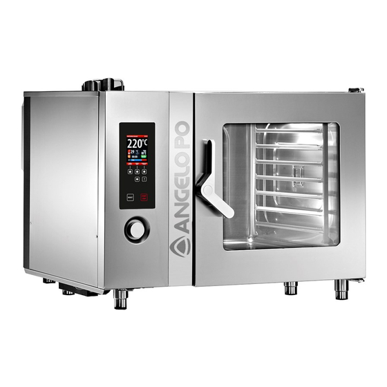
- Page 13 Section 3 GENERAL DESCRIPTION Main Parts A .– . B .– .Control board is designed and manufactured to cook foods in C .– .Oven door D .– .Cooking chamber environment. E .– . Functions are controlled by an electronic control F .–...
- Page 14 Section 3 DATAPLATE LOCATION AND APPLIANCE SPECIFICATIONS information for operating safety. B – Type of customization D – Serial number E – Reference standard F – Protection rating G – Country of destination O – Rated power P – Manifold pressure Q –...
- Page 15 Section 3 Description FX 61 G3 FX 101 G3 Oven dimensions 36.2 × 30.5 × (24.8 + 4 36.2 × 30.5 × (34.5 + 4 Rated power 576 W 828 W Power supply wire gauge Chamber opening dimensions 17.34 × 17.73” 17.34 ×...
- Page 16 Section 3 Description FX 82 G3 FX 122 G3 Oven dimensions 46.4 × 38.0 × (51.8 + 5.9 46.4 × 38.0 × (62.0 + 5.9 Rated power 900 W 960 W Power supply wire gauge Chamber opening dimensions 25.2 × 23.6” 25.2 ×...
-
Page 17: Handling And Installation
Section 4 Handling and Installation TRANSPORT AND INSTALLATION on the destination. IMPORTANT _________________________ The chart below shows the most commonly used When handling and installing the appliance alternatives. prevent unwanted shifting. the appliance and in the instructions for use. “safety plan” to protect the people directly involved. - Page 18 Section 4 Handling and Installation APPLIANCE INSTALLATION IMPORTANT _________________________ perform these operations must organize a “safety The location of the installation must have all the the location must be suitably lit and meet all local health department and hygiene requirements to prevent the contamination of foods.
- Page 19 Section 4 Handling and Installation LEVELLING Connect the appliance to the main power supply as follows. (A) to level the 1. Remove the screws and side panel (A). appliance. (B) to the appliance’s terminal board (C) and to the electrical system diagram provided at the back of the manual and using a cable with the following characteristics.
- Page 20 Section 4 Handling and Installation GAS CONNECTION WATER CONNECTION Make connections WARNING individual shutoff valve must be disconnected from WATER SUPPLY CONNECTION the gas supply piping system during any pressure testing of that system at test pressures in excess of IMPORTANT _________________________ from the gas supply piping system by closing its individual manual shutoff valve during any pressure...
- Page 21 Section 4 Handling and Installation Description Value >0.5 Pressure 30 – 60 psi or Salt and metallic ion content Required Chlorine Chlorides Sulphates Recommended Iron Copper Manganese 40÷150 ppm for steam production inside the cooking chamber. Hardness cause corrosion if combined with wrong usage and environment.
- Page 22 Section 4 Handling and Installation IMPORTANT _________________________ 1. Connect red pipe (A) to pipe (B) into the cleaner tank (D). 2. Connect blue pipe (E) to pipe (B) (C) into the sanitizing cleaner tank (F). IMPORTANT _________________________ appliance manufacturer for the best results. The chemical composition of the products referred to above is as follows: Cleaner:...
- Page 23 Section 4 Handling and Installation GAS SUPPLY CONVERSION IMPORTANT _________________________ WARNING WARNING WARNING that involves electrical connection disconnection and/or exposure to electrical LOCKOUT/TAGOUT Procedure. Disconnect The gas supply conversion WARNING The manufacturer has tested the appliance with its the nameplate. If the type of gas to be connected is different from 1.
- Page 24 Section 4 Handling and Installation WARNING that involves electrical connection disconnection and/or exposure to electrical IMPORTANT _________________________ LOCKOUT/TAGOUT Procedure. Disconnect WARNING 1. Turn on gas and water supply valves and check that connections are tight. 2. Turn on the master switch to check the electrical connection.
- Page 25 Section 4 Handling and Installation 9. Replace panel (B) and retighten screws when the operation is complete. (A). 2. Turn on water supply valve (B). (C). analyze the combustion exhaust gases: bring the pressure reading on pressure gauge the instrument in accordance with instructions in the operator’s manual supplied with it.
- Page 26 Section 4 Handling and Installation 26 Combination Oven Installation and Operation Manual...
-
Page 27: Operation
Section 5 Operation OPERATION RECOMMENDATIONS FOR USE F. Knob: or modify values. To select one of the zones IMPORTANT _________________________ zones or increases the value shown. zones or decreases the value shown. reduce the occurrence of accidents or value. errors. turns the appliance’s electricity H. - Page 28 Section 5 Operation ON AND OFF Proceed as follows: Lighting 1. Operate the appliance’s master switch to connect it to the electrical power supply. 2. Turn on gas supply valve. 3. Turn on water supply valve. 4. Press button (G) to turn on the appliance. 5.
- Page 29 Section 5 Operation The chart shows the various display pages covering the various operating modes. A. Presentation page: displayed when this is used to activate the appliance is switched on. function for the simultaneous managementof the B. Main functions page (home page): used to access the pages for programming and display of the used to select the type of program for cleaning of the appliance...
- Page 30 Section 5 Operation Proceed as follows. knob. using the knob. 5. Modify the value of the selected setting using the knob. VALUES Proceed as follows: required using the knob. >>> 30 Combination Oven Installation and Operation Manual...
- Page 31 Section 5 Operation selection. >>> 5. Repeat these steps until the entire value for the setting is displayed. description selected. >>> SETTINGS Proceed as follows. 1. Select the “Settings” function using the knob. >>> settings description selected. >>> Time The display will show page. >>>...
- Page 32 Section 5 Operation 5. Turn knob to select language required. >>> language language Preheating 1. Select “Preheating” function using the knob. preheating >>> preheating 3. Turn knob to activate or deactivate the cooking preheating >>> preheating Cooldown during cooking 1. Select “Cooldown during cooking” function using the knob.
- Page 33 Section 5 Operation Set date 1. Select “set date” function using the knob. >>> set date set date set date 3. Modify current date using the knob. >>> set date Set time set time 1. Select “set time” function using the knob. >>>...
- Page 34 Section 5 Operation >>> external probe external external probe external knob. >>> external probe vacuum external probe vacuum HACCP acquisition interval using the knob. >>> HACCP acquisition internal 5 min. HACCP acquisition internal 5 min. HACCP acquisition internal 9 min. HACCP acquisition internal 9 min.
- Page 35 Section 5 Operation 3. To activate or deactivate the cleaning function of water drain cleaning rotate knob. >>> IMPORTANT _________________________ water drain cleaning The function “Water drain cleaning” requires User parameters * * * * User parameters 1. To modify and thus personalize some preset User parameters * * * * 3.
- Page 36 Section 5 Operation Set sounds 1. To modify sounds attached to different oven set sounds knob. >>> set sounds The display will show. >>> end of the cooking end of the cooking red alert alert yellow alert alert end of the cleaning keys press key end of preheating.
- Page 37 Section 5 Operation audio volume 3. Modify audio volume using the knob. >>> audio volume audio volume “MANUAL COOKING” MODE Proceed as follows: 1. Select “manual cooking” function using the manual cooking knob. >>> selected. >>> The display will show: performed in “manual mode”.
- Page 38 Section 5 Operation you need to turn the cooking chamber preheating function on or off. 3. Press button to activate or deactivate the cooking >>> The operating status (“preheating on” or zone according to the selection. Cooking type 1. Select “cooking type” zone using the knob. >>> humidity inside the oven appears on a bar graph.
- Page 39 Section 5 Operation Cooking time or core temperature 1. Select either “cooking time” or “core temperature” using the knob. >>> cooking time 3. To modify value selected (“cooking time” or required is displayed. >>> cooking time Percentage humidity or steam vent percentage 1.
- Page 40 Section 5 Operation Fan speed 1. Select “fan speed” using the knob. >>> increase or reduce the number of bars on the graduated scale. >>> The symbol shows the cooling fan speed is on the minimum setting. >>> The symbol shows the cooling fan speed is on the maximum setting.
- Page 41 Section 5 Operation reduced loads. This function allows increasing the power of the machine. 6. Press button to start the cooking cycle (See another cooking type at a lower temperature proceed as follows: cooldown Cooldown 1. Press the button. >>> The display will show >>>...
- Page 42 Section 5 Operation 4. Press button for rapid cooling of the appliance. >>> During every cooking cycle it is possible to activate enable 1. To activate or deactivate press the button. >>> The display will show >>> >>> The display will show >>>...
- Page 43 Section 5 Operation 6. Turn knob to set cooking time. >>> Repeat the operation from point 4 to point 7 to set the other timers. 9. Press the button to start the countdown. >>> The display will show >>> Note: IMPORTANT _________________________ An acoustic signal is activated at the end of each cooking program.
- Page 44 Section 5 Operation “C3 AUTOMATIC COOKING” MODE Do the following: c3 automatic cooking 1. Select “C3 automatic cooking” function using the knob. >>> Time The display will show: >>> c3 automatic cooking for different foods. meat poultry C3 Automatic Cooking bread vegetables confectionery...
- Page 45 Section 5 Operation >>> roasted dishes c3 automatic cooking The display will show: >>> game rabbit pork beef Roast beef shin of pork 7. Select name of the cooking program using the knob. >>> game game game The display will show >>>...
- Page 46 Section 5 Operation 3. The display will show >>> aaabbb set as favorite set as favorite 4. Press the button. >>> >>> 6. Press button to start the cooking program. >>> Setting “Cooking It is possible to set the values displayed in the table for each setting in “C3 automatic cooking”.
- Page 47 Section 5 Operation “CF3 MEMORIZED COOKING” MODE Proceed as follows: 1. Select “CF3 memorized cooking” function using the knob. >>> CF3 memorized cooking selected. >>> The display will show >>> cooking of foods. confectionery >>> confectionery The display will show >>>...
- Page 48 Section 5 Operation 5. Select name of the cooking program using the knob. >>> program 3 program 3 To start “cooldown” press button and follow the instructions described on page 41. >>> cooldown multicooking and follow the instructions on page 42. >>>...
- Page 49 Section 5 Operation >>> 6. Press the button to start the programmed cooking operation at the set time. >>> 7. To start the programmed cooking operation start at once It is possible to temporarily change the program values when the cooking program has already change hour instructions from steps 2 to 5.
- Page 50 Section 5 Operation >>> program 3 The display will show this screen >>> intend to activate the “Delta T” function. >>> 9. Press the “Delta T” button to activate the function. >>> 10. Turn knob to set the desired “Delta T” function. >>>...
- Page 51 Section 5 Operation OF A COOKING PROGRAM 1. Select the name of the cooking program using the knob. >>> program 3 options 2. Press the button. >>> program library The display will show page. >>> new program rename copy delete add to favorites 3.
- Page 52 Section 5 Operation COPY: cooking program and save it with a new name. DELETE: program. ADD TO FAVORITES: used to save the chosen cooking program in the favorites category. DISPLAY RECIPE (USB): is used to display DISPLAY PHOTOS (USB): is used to display of the cooking programs memorized by the manufacturer by selecting from the...
- Page 53 Section 5 Operation REGENERATION AND BANQUETING Do The following; using the knob. >>> Time The screen where it is possible to carry out all functions described in the “CF3 memorized section appears on the display graphic Regeneration Banqueting “SPECIAL COOKING” MODE tray Do the following;...
- Page 54 Section 5 Operation It is possible to set the parameters reported in Setting “Cooking chamber the table at the side in every program of the “special cooking”. >>> Setting “Product core Setting the percentage percentage Do The following; >>> The display will show page >>>...
- Page 55 Section 5 Operation The display will show >>> Boiled foods IMPORTANT _________________________ The cooking programs stored by the manufacturer are listed in capital letters, while those entered by the user are listed in lower case. TRADICIONAL STEAM 96°C DELICATE STEAM 85°C FORCED STEAM 125°C...
- Page 56 Section 5 Operation The display will show >>> TRADITIONAL STEAM ASPARAGUS SWISS CHARD VACUUM PACKED SWISS BRUSSELS SPROUTS WHOLE CARROTS SLICED CARROTS ONION SEGMENTS SLICED ONIONS FRENCH BEANS new program 8. Select the name of the cooking program using FRENCH BEANS the knob.
- Page 57 Section 5 Operation 4. Press the knob to enable the alteration. >>> FRENCH BEANS time plat 00:15 5. Turn the knob to set the value. >>> FRENCH BEANS time plat 00:25 Repeat from step 3 to 6 if you wish to set the baking FRENCH BEANS tray parameter.
- Page 58 Section 5 Operation Press the button to temporarily edit the cooking parameters. >>> modify multy IMPORTANT _________________________ The parameters that can be edited are the temperature, humidity, fan speed, as indicated in Press the button to temporarily edit the cooking parameters.
- Page 59 Section 5 Operation the knob. >>> modify modify >>> RENAME: it is used to assign a new name to the selected cooking program. it is used to cooking program. COPY: cooking program and rename it. DELETE: it is used to delete the selected cooking program.
- Page 60 Section 5 Operation edited using the knob >>> TRADITIONAL STEAM French beans Artichoke segments Turnip tops Mushrooms In Garlic And Parsley Braised Endives Fish in pieces modify time delete new program 1. Press button. >>> modify time 2. Set the new value using the knob. >>>...
- Page 61 Section 5 Operation Do the following; automatic cleaning 1. Select the “automatic washing” function using the knob. >>> Time The display will show >>> This screen is used to select the type of program for cleaning of the appliance. 3. Check there is at least 1 liter of cleaning products respective tanks.
- Page 62 Section 5 Operation The display will show >>> TIME LEFT 3. When the beeper sounds (about 5 min. after >>> detergent onto all the walls of the cooking Use of the “cleaner spray” accessory and PLACE THE DETERGENT IMPORTANT _________________________ When cleaning and sanitising the appliance with detergents, wear personal protection equipment (gloves, masks, goggles, etc.) as required by the...
- Page 63 Section 5 Operation IMPORTANT _________________________ enable drain washing IMPORTANT _________________________ long rinse cycle” and “short splash rinse enable ECO phase from the various cleaning programs resulting in energy savings. a beeper sounds and this screen appears on the display. >>> 7.
- Page 64 Section 5 Operation 10. Press the “emergency rinse cycle” button and wait for the cleaning cycle to end. >>> rinse in emergency 11. Press the button to return to the previous page. >>> COOKING CYCLE START AND END PROCEDURE To start a cooking cycle (in manual or programmed 2.
- Page 65 Section 5 Operation the button. >>> end preheating button and proceed as described on page 38. modify temperature >>> 4. Place the foods for cooking inside the cooking chamber and close the door to start the cooking cycle. Time manual cooking The display will show this screen.
- Page 66 Section 5 Operation 7. Press the button. >>> modify parameters described in point “Manual cooking” mode” (see by using the knob. temperature of the cooking chamber; press the cooking time or the core temperature; press the The cooking cycle stops automatically at the end of the set time or when the “product core probe”...
- Page 67 Section 5 Operation manual cooking cycle. Note: It is possible to save up to a maximum 18 1. Press the button to return to the main functions page “Home page”. >>> 2. Select “Settings” function using the knob. >>> settings 4.
- Page 68 Section 5 Operation memorized (see page 30 “How to enter alphanumerical IMPORTANT _________________________ Proceed as follows: >>> haccp The display will show >>> month year The screen is used to display the measured cooking data and the alarms that have been used.
- Page 69 Section 5 Operation month year acquisitions 7. Press the knob to access the cooking modes. month year >>> acquisitions program 1 9. Press the button to return to the previous page. >>> display alarms 10. Press the button to display the alarms intervened during cooking.
- Page 70 Section 5 Operation 3. Select the function required from the list using the knob. >>> Press the button to select all cooking programs select all Alternatively, select the individual programs to The selected programs will be highlighted with the symbol ( Press button to start the operation.
- Page 71 8. Press “more movies?” button to display the website link to download other movies. >>> more recipes? 9. The display will show >>> Angelo Po Grandi Cicine Spa www.combistarfx.it bbbb cccc more images. and recipes associated to the cooking program 2.
- Page 72 Section 5 Operation 4. Turn knob to select type of food. >>> meat meat 6. Select the name of the cooking program using the knob. >>> grilled spare pork ribs option 8. Select “Current language” function using the knob. >>> Display photos (USB) Display photos (USB) display photos...
- Page 73 Section 5 Operation 12. The display will show >>> www.combistarfx.it LONG DOWNTIMES OF APPLIANCE proceed as follows: 1. Turn off gas supply valve. 2. Turn off water supply valve. 3. Cut off main electrical supply using the appliance’s master switch. 4.
- Page 74 Section 5 Operation 74 Combination Oven Installation and Operation Manual...
-
Page 75: Maintenance
Section 6 Maintenance MAINTENANCE MAINTENANCE RECOMMENDATIONS dioxide (CO performing the scheduled maintenance procedures recommended manufacturer. Proper longer working life and constant maintenance of safety requirements. WARNING IMPORTANT _________________________ Record the yearly inspections. IMPORTANT _________________________ representative or an authorized service unexpected health and safety hazards if turned on. - Page 76 Section 6 Maintenance STAINLESS STEEL CARE RECOMMENDATIONS FOR CLEANING Cleaning Since the appliance is used for preparing foods for human surrounding environment must constantly be kept clean. Table of Cleaning Products Description Products For washing and rinsing Tap water at room follow these steps: temperature CAUTION...
- Page 77 Section 6 Maintenance WARNING Never use products containing the cooking chamber with water. 7. Rinse surfaces with clean tap water and dry. 9. Take special care not to damage stainless steel onto the inside of the cooking chamber. products or chlorines and do not use abrasive materials or sharp tools.
- Page 78 Section 6 Maintenance (A) and (B) greaser. 1. Switch off the appliance. IMPORTANT _________________________ the electrical main. 1. Clean and drain the condensation collection channel (A). 2. Clean the condensation collection tank (B) and check that the drain hole and line are not blocked.
-
Page 79: Parts Replacement
Section 7 Parts Replacement PARTS REPLACEMENT REPLACING PARTS RECOMMENDATIONS NOZZLE IMPORTANT _________________________ (A). 2. Disconnect gas supply line (B). parts only. instructions provided in the parts catalog. WARNING that involves electrical connection (C) and replace it with one suitable disconnection and/or exposure to electrical LOCKOUT/TAGOUT Procedure. - Page 80 Section 7 Parts Replacement WARNING WARNING that involves electrical connection that involves electrical connection disconnection and/or exposure to electrical disconnection and/or exposure to electrical LOCKOUT/TAGOUT Procedure. Disconnect LOCKOUT/TAGOUT Procedure. Disconnect WARNING WARNING (A). (A). (B) and replace damaged fuse (C). 2.
- Page 81 Section 7 Parts Replacement WARNING WARNING that involves electrical connection that involves electrical connection disconnection and/or exposure to electrical disconnection and/or exposure to electrical LOCKOUT/TAGOUT Procedure. Disconnect LOCKOUT/TAGOUT Procedure. Disconnect of procedures must be carried out to ensure the WARNING appliance and its components are no longer an obstacle and are not easily accessible.
- Page 82 Section 7 Parts Replacement 82 Combination Oven Installation and Operation Manual...
-
Page 83: Troubleshooting
Section 8 Troubleshooting The appliance has been tested before being put into The user can solve some of these problems on their service. or skill is required. More advanced troubleshooting The information provided below is intended to assist may need to be done by an authorized service agent. and malfunctions which might occur during use. - Page 84 Section 8 Troubleshooting KEY TO ALARM TABLE Alarm Fault Remedy Notes Check that mains water is Convection cooking cycles can still water pressure too low be performed persists call an authorized service agent H2O. Check that water supply is Convection and steam cooking pressure too low cycles can still be performed persists call an authorized...
- Page 85 Section 8 Troubleshooting KEY TO ALARM TABLE (Continued Alarm Fault Remedy Notes The oven solves the problem on its own The oven’s functions are compartment has enabled; cooking cycles overheated can be performed Call an authorized service agent The oven’s functions are diagnostics tripped enabled;...
- Page 86 Section 8 Troubleshooting KEY TO ALARM TABLE (Continued Alarm Fault Remedy Notes Core probe not inserted in Insert the core probe The oven’s functions are the food enabled; cooking cycles can be performed 1 Chamber inverter Call an authorized service The oven’s functions are anomaly agent...
-
Page 87: Connection And Wiring Diagrams
Section 9 Connection and Wiring Diagrams CONNECTION AND WIRING DIAGRAMS Combination Oven Installation and Operation Manual... - Page 88 Section 9 Connection and Wiring Diagrams 88 Combination Oven Installation and Operation Manual...
- Page 89 Section 9 Connection and Wiring Diagrams Combination Oven Installation and Operation Manual...
- Page 90 Section 9 Connection and Wiring Diagrams 90 Combination Oven Installation and Operation Manual...
- Page 91 Section 9 Connection and Wiring Diagrams Combination Oven Installation and Operation Manual...
- Page 92 Section 9 Connection and Wiring Diagrams 92 Combination Oven Installation and Operation Manual...
- Page 93 Section 9 Connection and Wiring Diagrams Combination Oven Installation and Operation Manual...
- Page 94 Section 9 Connection and Wiring Diagrams 94 Combination Oven Installation and Operation Manual...
- Page 95 Section 9 Connection and Wiring Diagrams Combination Oven Installation and Operation Manual...
- Page 96 Section 9 Connection and Wiring Diagrams 96 Combination Oven Installation and Operation Manual...
- Page 97 Section 9 Connection and Wiring Diagrams Combination Oven Installation and Operation Manual...
- Page 98 98 Combination Oven Installation and Operation Manual...
-
Page 99: Index
Section 10 Index INDEX ......25 Gas connection ..........20 ..........83 Gas supply Conversion ........23 ........18 General description ..........13 .......61 General safety information ........5 “C3 automatic cooking” mode ......44 Handling and lifting ..........17 ........18 .............68 “CF3 memorized cooking” mode .......47 How to access the menu pages .......30 Changing the ignition plug .......81 How to enter alphanumerical values ....30 Changing the lamp ...........80... - Page 100 Section 10 Index Purpose of the manual ........11 ....24 Recommendations for cleaning ......76 Recommendations for handling and installation ..17 Recommendations for use .......27 Replacing the fuse ...........80 Replacing parts recommendations ....79 Replacement of the burner nozzle ....79 Room ventilation ..........18 Safety label and sign location ......8 Safety precautions ..........5 Safety devices ..........12...
- Page 102 427 Sargon W “E” UITE Horsham, Pennsylvania 19044 www.angelopoamerica.com...
- Page 103 Manuel d’installation et mode d’emploi Modèles FX61 G3 FX101 G3 FX82 G3 FX82 G3T FZ122G3 FX122 G3T FX201 G3 FX202 G3 Lisez et familiarisez-vous avec ce manuel avant d’essayer d’installer, faire fonctionner ou dépanner ce matériel. Ce manuel est destiné à être utilisé uniquement par des installateurs CONSERVEZ LE MANUEL POUR POUVOIR LE CONSULTER À...
- Page 104 IMPORTANT POUR VOTRE SÉCURITÉ Ce manuel est destiné à être utilisé uniquement par des installateurs les modes d’emploi destinés aux utilisateurs de cet électroménager. Conservez ce manuel dans un endroit facilement accessible pour permettre aux différents opérateurs de le consulter si nécessaire. En cas de panne de courant, ne tentez pas de faire fonctionner cet électroménager.
- Page 105 Avertissements de sécurité ... . . 5 Informations générales....11 Caractéristiques Techniques ... 13 Manutention et Installation .
-
Page 107: Avertissements De Sécurité
Section 1 Avertissements de sécurité AVERTISSEMENTS DE SÉCURITÉ SÉCURITÉ de toute contamination. produits détergents pour usage alimentaire. fabricant a fait particulièrement attention aux facteurs qui peut provoquer des risques pour la santé et la sécurité de toute personne en des substances nocives à la santé des personnes. toutes les exigences légales lors de la fabrication et de l’assemblage de cet électroménager. - Page 108 AVERTISSEMENT Avant de cuisiner avec l’appareil, AVERTISSEMENT assurez-vous qu’il n’y a pas de détergents ou ANGELO PO AMERICA décline d’autres résidus de nature caustique dans le toute responsabilité pour toute situation four.
- Page 109 Section 1 Avertissements de sécurité décline toute AVERTISSEMENT responsabilité pour toute situation découlant des chariots rotatifs peuvent se retourner le long des travaux exécutés par des techniciens non formés. surfaces inégales ou au moment de franchir le seuil d’une porte. AVERTISSEMENT Portez AVERTISSEMENT...
- Page 110 Section 1 Avertissements de sécurité Manuel d’installation et mode d’emploi du four combiné...
- Page 111 Section 1 Avertissements de sécurité Cet appareil peut etre utilsè SIGNES seulement avec leconduit d’evacuation fumèes fournies. Pour une installation sous une hotte d’evacuation seulement. Cet appareil 2 Borne équipotentiel se reporter aux instructions d’installation. locales en vigueur sur les travaux de plomberie. Pour réduire le risque de shock de protection.
- Page 112 Section 1 Avertissements de sécurité 10 Manuel d’installation et mode d’emploi du four combiné...
-
Page 113: Informations Générales
Section 2 Informations générales fournir les informations nécessaires à ceux qui manuel contient toutes informations sont autorisés à interagir avec celui-ci pendant nécessaires pour les utilisateurs autorisés de sa vie. l’appareil. non seulement adopter une bonne technique attentivement les indications et les appliquer de façon rigoureuse. - Page 114 Section 2 Informations générales DISPOSITIFS DE SÉCURITÉ AVERTISSEMENT pour respecter les lois en vigueurs. ATTENTION are utilisées pour protéger le personnel travaillant sur un électroménager électrique. D’INFORMATION Avant d’effectuer toute opération d’entretien ou de réparation qui exige l’exposition aux composants Voir le graphique «Étiquette de sécurité...
-
Page 115: Caractéristiques Techniques
Section 3 Caractéristiques techniques Organes principaux A .– .Boîtier des composants électriques B .– .Tableau de commandes et fabriqué pour faire cuire des aliments dans un C .– .Porte du four environnement de restauration professionnel de D .– .Chambre de cuisson E .–... - Page 116 Section 3 Caractéristiques techniques A – Modèle de l’appareil D – Numéro de série E – Norme de référence F – Degré de protection H – Marques de conformité O – Puissance déclarée P – Pression du collecteur DEMANDE D’ASSISTANCE que la description du problème.
- Page 117 Section 3 Caractéristiques techniques Description FX 61 G3 FX 101 G3 Dimensions du four 36.2 × 30.5 × (24.8 + 4 36.2 × 30.5 × (34.5 + 4 Alimentation électrique Puissance déclarée 50000 Btu/h 71000 Btu/h Puissance électrique absorbée 576 W 828 W Section des câbles d’alimentation 12 AWG...
- Page 118 Section 3 Caractéristiques techniques Description FX 82 G3 FX 122 G3 Oven dimensions 46.4 × 38.0 × (51.8 + 5.9 46.4 × 38.0 × (62.0 + 5.9 Rated power 92500 Btu/h 115000 Btu/h 900 W 960 W 12 AWG 12 AWG Chamber opening dimensions 25.2 25.2 ×...
-
Page 119: Manutention Et Installation
Section 4 Manutention et installation TRANSPORT IMPORTANT _________________________ courantes. correctement pour éviter tout déplacement non désiré. transport adopté. faite avec certains composants démontés et opportunément protégés et emballés. Sur l’emballage sont reportées toutes les informations nécessaires au chargement et au déchargement. de levage à... - Page 120 Section 4 Manutention et installation IMPORTANT _________________________ considérées selon l’étude du site et l’emplacement ces opérations doivent développer un «plan de sécurité» pour protéger les personnes directement relatives aux chantiers mobiles. résidus de production requis. En plus l’emplacement en vigueur pour éviter la contamination des aliments. Il est suggéré...
- Page 121 Section 4 Manutention et installation MISE À NIVEAU Effectuer le branchement de l’appareil au réseau électrique d’alimentation comme suit. Agir sur les pieds d’appui (A) pour mettre de niveau 1. Dévisser les vis et démonter le panneau latéral (A). l’appareil. 2.
- Page 122 Section 4 Manutention et installation RACCORDEMENT DU GAZ AVERTISSEMENT IMPORTANT _________________________ coupure de l’alimentation un si nécessaire. IMPORTANT _________________________ ATTENTION L’appareil doit être alimenté avec de l’eau potable dont les caractéristiques sont ATTENTION Effectuer raccordement indiquées sur le tableau. Si ces caractéristiques conformément aux lois en vigueur à...
- Page 123 Section 4 Manutention et installation Description Valuer >0.5 Pressure 30 – 60 psi or 200 - 400 kPa Contenu de sels et d’ions métalliques Requis Chlore < 0.1 mg/l Chlorures < 30 mg/l Sulfates < 30 mg/l < 0.1 mg/l Recommended Cuivre <...
- Page 124 Section 4 Manutention et installation RACCORDEMENT EVACUATION DES IMPORTANT _________________________ Jaune (A) (B) et (C) dans le bidon (D) du détergent. Vert (E) (B) et (C) dans le bidon (F) du stérilisant. IMPORTANT _________________________ stérilisant fournis par le fabricant du four pour obtenir un très bon résultat.
- Page 125 Section 4 Manutention et installation TRANSFORMATION DE IMPORTANT _________________________ AVERTISSEMENT AVERTISSEMENT AVERTISSEMENT ou une solution d’eau savonneuse AVERTISSEMENT (A). appliqué sur la plaquette (B) et mettre le 4. Accéder au menu « Service » et faire partir la procédure de « Transformation alimentation du Manuel d’installation et mode d’emploi du four combiné...
- Page 126 Section 4 Manutention et installation AVERTISSEMENT Avant d’effectuer toute réparation qui implique la connexion ou la déconnexion IMPORTANT _________________________ électrique et / ou l’exposition à des composants Avant la mise en service, l’essai de l’installation doit VERROUILLAGE ÉTIQUETAGE électriques. être fait pour évaluer les conditions opérationnelles Débranchez tous les circuits.
- Page 127 Section 4 Manutention et installation COMBUSTION 1. Dévisser les vis et démonter le panneau latéral (A). 2. Ouvrir le robinet d’alimentation de l’eau (B). 3. Dévisser la bague (C). tarage de l’instrument en suivant les indications reportées dans le manuel d’utilisation de 4.
- Page 128 Section 4 Manutention et installation 26 Manuel d’installation et mode d’emploi du four combiné...
-
Page 129: Fonctionnement
Section 5 Fonctionnement FONCTIONNEMENT RECOMMANDATIONS POUR elle sert pour IMPORTANT _________________________ elle sert pour sélectionner la fonction manette en sens horaire ou anti-horaire. le bas » ou on augmente la valeur mise en évidence. vers le haut » ou on diminue la valeur mise ou d’erreurs en évidence. - Page 130 Section 5 Fonctionnement Procéder comme suit: Allumage 1. Agir sur l’interrupteur sectionneur de l’appareil pour activer le branchement à la ligne électrique principale. 3. Ouvrir le robinet d’alimentation de l’eau. 4. Presser la touche (G) pour activer l’appareil. fonctions principales de l’appareils. Extinction IMPORTANT (G) pour désactiver...
- Page 131 Section 5 Fonctionnement des pages principales relatives aux différents modes de fonctionnement. de l’appareil. elle elle sert à activer la fonction sert pour accéder aux pages de programmation de gestion simultanée des processus de cuisson elle sert pour elle sert pour paramètres de fonctionnement de l’appareillage sert pour fonction...
- Page 132 Section 5 Fonctionnement MENUS Procéder comme suit. avec la manette. fonction mise en évidence. manette. paramètre mis en évidence. avec la manette. Procéder comme suit: 1. Mettre en évidence le premier caractère (lettre sélection mise en évidence. >>> 3. Mettre en évidence le second caractère (lettre >>>...
- Page 133 Section 5 Fonctionnement sélection mise en évidence. >>> la description complète. description mise en évidence. >>> Procéder comme suit. manette. >>> description mise en évidence. >>> Horaire fonctionnement de l’appareil. langue préchauffage data horloge volume son Sonde externe Externe Intervalle acquisition HACCP 5 min.
- Page 134 Section 5 Fonctionnement 5. Tourner la manette pour sélectionner la langue choisie. >>> langue langue paramètre mis en évidence. >>> Préchauffage 1. Sélectionner la fonction « Préchauffage » avec préchauffage la manette. >>> fonction mise en évidence. >>> préchauffage 3. Pour activer ou désactiver (« activer/désactiver le préchauffage préchauffage fonction mise en évidence.
- Page 135 Section 5 Fonctionnement Réglage date 1. Sélectionner la fonction « Réglage date » avec Réglage date la manette. >>> Réglage date fonction mise en évidence. >>> Réglage date Réglage date paramètre mis en évidence. >>> Réglage heure 1. Sélectionner la fonction « Réglage heure » avec la manette.
- Page 136 Section 5 Fonctionnement Sonde externe ou Sous vide 1. Sélectionner la fonction « sonde externe » avec la manette. >>> sonde externe externe fonction mise en évidence. >>> sonde externe externe 3. Autrement sélectionner la fonction “Sous vide sonde externe sous vide avec la manette.
- Page 137 Section 5 Fonctionnement 3. Pour activer ou désactiver la fonction de Nettoyage vidange eau paramètre mis en évidence. >>> Nettoyage vidange eau IMPORTANT _________________________ La fonction “Nettoyage vidange de l’eau” comporte cette fonction seulement si cela est nécessaire, par exemple pour des cuissons fréquentes d’aliments gras (poulets, rôtis, etc.).
- Page 138 Section 5 Fonctionnement sélectionner la fonction “ avec la manette. >>> fonction mise en évidenc. >>> alerte rouge alerte touches presser les touches lavage semi-automatique 3. Sélectionner fonction choisie avec manette. >>> des sonneries. >>> wowo son 25 son 24 son 23 son 19 son 18...
- Page 139 Section 5 Fonctionnement fonction mise en évidence. >>> volume son volume son volume son paramètre mis en évidence. >>> Procéder comme suit: cuisson manuelle 1. Sélectionner la fonction « cuisson manuelle » avec la manette. >>> description mise en évidence. >>>...
- Page 140 Section 5 Fonctionnement s’il faut activer ou désactiver le préchauffage de la désactiver le chambre de cuisson. préchauffage 3. Pour activer ou désactiver (« activer/désactiver le « préchauffage » apparaît l’état de fonctionnement (« activer le préchauffage » ou « désactiver le Type de cuisson type de cuisson »...
- Page 141 Section 5 Fonctionnement mise en évidence. >>> Temps de cuisson ou température à coeur temps de cuisson » temps de cuisson >>> mise en évidence. >>> Si l’on sélectionne la fonction « temps de cuisson » est annulée ou vice versa. >>>...
- Page 142 Section 5 Fonctionnement Vitesse du ventilateur vitesse du ventilateur » avec la manette. >>> mise en évidence. >>> augmenter ou diminuer le nombre de divisions de l’échelle graduée. >>> mise en évidence. >>> est programmé à la vitesse minimale. >>> refroidissement programmé...
- Page 143 Section 5 Fonctionnement mais uniquement pour des charges réduites. Cette fonction permet d’utiliser l’appareil avec une puissance plus importante. fonction mise en évidence. >>> Cooldown cooldown 1. Presser la touche. >>> 2. Sélectionner la température de refroidissement avec la manette. >>>...
- Page 144 Section 5 Fonctionnement 4. Presser touche pour effectuer refroidissement rapide de l’appareil. >>> Multicooking Activer 1. Pour activer ou désactiver “active/désactive multicooking manette. >>> mise en évidence. >>> les Timers. Effacer tout cuisson continue 42 Manuel d’installation et mode d’emploi du four combiné...
- Page 145 Section 5 Fonctionnement 4. Sélectionner l’un des timers avec la manette. >>> fonction mise en évidence. >>> manette. >>> fonction mise en évidence. >>> Répéter l’opération du point 4 au point 7 pour fonction mise en évidence. >>> à rebours. >>>...
- Page 146 Section 5 Fonctionnement Procéder comme suit. Cuisson automatique C3 1. Sélectionner la fonction “Cuisson automatique C3 avec manette. >>> mise en évidence. >>> Horaire Cuisson automatique C3 viande volailles poisson Cuisson automatique C3 pain légumes desserts pâtes favoris >>> viande mis en évidence.
- Page 147 Section 5 Fonctionnement rôtis de cuisson mis en évidence. >>> Cuisson automatique C3 gibier lapin porc boeuf Roast beef 7. Sélectionner le nom du programme de cuisson avec la manette. >>> gibier fonction mise en évidence. >>> gibier gibier programme. >>>...
- Page 148 Section 5 Fonctionnement fonction mise en évidence. >>> aaabbb rendre favoris rendre favoris 4. Presser la touche. >>> 5. Tourner la manette pour sélectionner le texte programme de cuisson >>> Sélection “température chambre de cuisson” Dans chaque programme “Cuissons Sélection “temps” reportés dans le tableau ci-contre.
- Page 149 Section 5 Fonctionnement MÉMORISÉES CF3 Procéder comme suit: 1. Sélectionner la fonction « programmes » avec la Cuissons mémorisées CF3 manette. >>> description mise en évidence. >>> Horaire programmer la cuisson des aliments. viande volailles poisson Cuisson mémorisées CF3 pain légumes desserts pâtes...
- Page 150 Section 5 Fonctionnement 5. Sélectionner le nom du programme de cuisson avec la manette. >>> programme 3 fonction mise en évidence. >>> programme 3 Pour démarrer le “cooldown cooldown >>> Pour activer le “Multicooking multicooking >>> programme de cuisson. >>> Heure de mise en marche Pour faire partir la cuisson programmée à...
- Page 151 Section 5 Fonctionnement mise en évidence. >>> la cuisson avec la manette. >>> mise en évidence. >>> 6. Presser la touche pour faire partir la cuisson programmée à l’horaire sélectionné. >>> 7. Pour faire partir immédiatement la cuisson départ immédiat temporairement les paramètres d’un programme heure bouton et suivre les instructions des points 2 à...
- Page 152 Section 5 Fonctionnement mis en évidence. >>> programme 3 au cours de laquelle on souhaite activer la mis en évidence. >>> 7. Sélectionner la température à l’aide de la manette. >>> mis en évidence. >>> fonction. >>> >>> mis en évidence. >>>...
- Page 153 Section 5 Fonctionnement DES PROGRAMMES DE CUISSON 1. Sélectionner le nom du programme de cuisson avec la manette. >>> programme 3 options 2. Presser la touche. >>> bibliothèque des programmes nouveau programme renommer copier éliminer rendre favori 3. Sélectionner de la liste la fonction choisie avec la manette.
- Page 154 Section 5 Fonctionnement sert pour effectuer le « copier-coller » du programme de cuisson sélectionné et le renommer. sert pour éliminer le programme de cuisson sélectionné. sert pour « enregistrer » le programme de cuisson choisi dans la catégorie favoris. des programmes de cuisson mémorisés par le fabricant en sélectionnant à...
- Page 155 Section 5 Fonctionnement Procéder comme suit: 1. Sélectionner fonction “régénération/ regeneration / banqueting fonction mise en évidence. >>> Time regeneration / banqueting Sur l’écran apparaît la page où l’on peut exécuter toutes les fonctions décrites dans le paragraphe >>> Regeneration Banqueting dans l’assiette-moitié...
- Page 156 Section 5 Fonctionnement Dans chaque programme “Cuisson Sélection “température spéciales chambre de cuisson reportés dans le tableau ci-contre. >>> Sélection “temps” Sélection “températureà coeur” Sélection “roussiment” Sélection “chargement plaques”” Sélection “Delta T” Réglage pourcentage humidité / sortie vapeur Suivre les instructions. multi-easy 1.
- Page 157 Section 5 Fonctionnement Boiled foods IMPORTANT _________________________ Les cuissons sauvegardées par le fabricant sont énumérées en lettres capitales, tandis que celles introduites par l’utilisateur sont en lettres minuscules. TRADICIONAL STEAM 96°C DELICATE STEAM 85°C FORCED STEAM 125°C INTENSE STEAM 120°C LIGHT STEAM 70°C options...
- Page 158 Section 5 Fonctionnement TRADITIONAL STEAM ASPERGES ---- ---- ---- ---- ---- ---- ---- HARICOTS VERTS nouveau programme 8. Sélectionner le nom du programme de cuisson à HARICOTS VERTS l’aide du bouton de réglage. >>> 9. Sélectionner le nom du programme de cuisson à HARICOTS VERTS l’aide du bouton de réglage.
- Page 159 Section 5 Fonctionnement HARICOTS VERTS temp plat HARICOTS VERTS une nouvelle valeur. >>> temp plat la valeur. >>> FRENCH BEANS temp plat paramètre du plat. précédente. >>> IMPORTANT _________________________ Les cuissons ont été sauvegardées mais ne sont pas encore actives. 8.
- Page 160 Section 5 Fonctionnement momentanément les paramètres de cuisson. >>> IMPORTANT _________________________ la température, l’humidité, la vitesse du ventilateur, comme il est indiqué pour la modalité de « cuisson manuelle » (voir pag. 38). supprimer cuisson de la liste. >>> MODIFICATION DES IMPORTANT _________________________ Les cuissons sauvegardées par le fabricant n’admettent que la fonction de «...
- Page 161 Section 5 Fonctionnement 3. Sélectionner la fonction souhaitée de la liste à l’aide du bouton de réglage. >>> mis en évidence. >>> pour attribuer un nouveau nom au programme de cuisson sélectionné. ipour cuisson sélectionné. pour « copier-coller » le programme de cuisson sélectionné...
- Page 162 Section 5 Fonctionnement GESTION DES PROGRAMMES VAPEUR CLASSIQUE Haricots verts ---- ---- ---- ---- ---- nouveau supprimer programme de réglage. >>> supprimer programme sur lequel se trouve le curseur. >>> nouveau pour la «modalité de saisie des valeurs programme alphanumériques » page 30 pour nommer le de réglage pour saisir le temps comme décrit aux points 3 et 4.
- Page 163 Section 5 Fonctionnement Procéder comme suit. lavage automatique 1. Sélectionner la fonction « lavage automatique » avec la manette. >>> description mise en évidence. >>> Horaire programme pour le lavage de l’appareil. au moins 1 litre chacun. lavage standard lavage medium lavage basic Programmes lavage soft...
- Page 164 Section 5 Fonctionnement TEMPS RÉSIDUEL apparaît la page. >>> 4. Ouvrir la porte et vaporiser le détergent pour usage alimentaire sur les parois de la chambre METTRE LE DÉTERGENT IMPORTANT _________________________ Quand on utilise des produits détergents pour le nettoyage et l’hygiénisation de l’appareil, porter les équipementMs de protection individuels (gants, masques, lunettes, etc.) conformément aux lois en vigueur en matière de sécurité...
- Page 165 Section 5 Fonctionnement IMPORTANT _________________________ active lavage vidange IMPORTANT _________________________ activer ECO éliminer des divers programmes de lavage la phase de séchage/assainissement d’énergie. indiqué par l’activation d’un signal sonore et par sonore. >>> Manuel d’installation et mode d’emploi du four combiné...
- Page 166 Section 5 Fonctionnement rinçage d’urgence 11. Presser la touche pour retourner à la page précédente. >>> les paramètres nécessaires au fonctionnement 3. Presser la touche. >>> Horaire préchauffage est active. Température chambre de cuisson Avant d’enfourner les aliments dans la chambre de Température de préchauffage la page.
- Page 167 Section 5 Fonctionnement pressant la touche. >>> terminer préchauffage presser la touche et procéder comme indiqué à temperature la page 38. >>> 4. Enfourner les aliments dans la chambre de cuisson et fermer la porte pour commencer le Horaire cuisson manuelle IMPORTANT _________________________ Temps de cuisson Icône brûleur allumé...
- Page 168 Section 5 Fonctionnement 7. Presser la touche. >>> paramètres comme indiqué dans le paragraphe « Modalités pour température dans la chambre de cuisson et le utilisant la manette. mémorisées C3; temps de cuisson ou la température à coeur; lorsque le temps programmé est écoulé ou lorsque la «...
- Page 169 Section 5 Fonctionnement ACTIVER SAUVEGARDE CUISSON dernière cuisson manuelle. possible d’enregistrer manette. >>> mise en évidence. >>> 4. Sélectionner la fonction « Activer sauvegarde Activer sauvegarde cuisson cuisson » avec la manette. >>> Activer sauvegarde cuisson mise en évidence. >>> Choisir ou mémoriser le programme en actionnant la manette >>>...
- Page 170 Section 5 Fonctionnement 8. Entrer le nom du programme de cuisson que IMPORTANT _________________________ HACCP Procéder comme suit. haccp 1. Sélectionner la fonction “HACCP manette. >>> mise en évidence. >>> mois année cuisson mesurées et les alarmes intervenues. mois année mois année fonction mise en évidence.
- Page 171 Section 5 Fonctionnement 6. Tourner manette pour sélectionner mois année “Acquisitions acquisitions mois année cuissons. >>> acquisitions programme 1 fonction mise en évidence. >>> 9. Presser la touche pour retourner à la page précédente. >>> alarmes intervenues pendant les cuissons. >>>...
- Page 172 Section 5 Fonctionnement 3. Sélectionner de la liste la fonction choisie avec la manette. >>> transmettre programmes de cuisson programmes de cuisson à charger et/ou à sélectionner décharger. >>> tous En alternative sélectionner les chacun des programmes à charger/décharger. Les programmes sélectionnés seront mis en évidence avec le symbole ( exécuter l’opération.
- Page 173 >>> bouton. >>> Plus de vidéos? d’autres vidéos. >>> MONTRER PHOTOS ET RECETTES Angelo Po Grandi Cicine Spa www.combistarfx.it bbbb cccc images. laquelle ont été téléchargées auparavant les photos et les recettes associées au programme 2. Sélectionner la fonction « cuissons mémorisées CF3 »...
- Page 174 Section 5 Fonctionnement >>> Viande fonction mise en évidence. >>> Viande 6. Sélectionner le nom du programme de cuisson avec la manette. >>> cotes de porc grilles options mise en évidence >>> 8. Sélectionner la fonction «Visualiser photos Visualiser photos (USB) Visualiser photos (USB) mise en évidence.
- Page 175 Section 5 Fonctionnement Angelo Po Grandi Cicine Spa www.combistarfx.it procéder comme suit: 2. Fermer le robinet d’alimentation de l’eau. 4. Agir sur l’interrupteur sectionneur de l’appareil pour désactiver le branchement à la ligne électrique principale. limitrophes. 5. Étaler un voile d’huile alimentaire sur les surfaces en acier inox.
- Page 176 Section 5 Fonctionnement 74 Manuel d’installation et mode d’emploi du four combiné...
-
Page 177: Entretien
Section 6 Entretien ENTRETIEN RECOMMANDATIONS POUR Maintenir l’appareil en parfait état de fonctionnement en effectuant les opérations d’entretien programmé dans les fumées évacuées. longue durée et un maintien constant des conditions de sécurité requises. AVERTISSEMENT Avant toute intervention d’entretien, activer tous les dispositifs de sécurité... - Page 178 Section 6 Entretien NETTOYAGE Nettoyage Étant donné que l’appareil est utilisé pour la préparation de rouiller s’il n’est pas bien entretenu. Il anche contient Tableau des produits pour le nettoyage se décomposer. Pour prévenir la dégradation de l’acier Description Produits ATTENTION Pour laver et rincer Eau potable à...
- Page 179 Section 6 Entretien 7. De rincer les surfaces avec de l’eau potable et 6. Vaporiser le détergent pour usage alimentaire et 9. De faire attention aux surfaces en acier inox pour (E) Pour vaporiser le détergent sur les parties de matériau abrasif ou d’outils tranchants. conseillé...
- Page 180 Section 6 Entretien (A) et (B) placés sous dégraissant approprié. 1. Eteindre l’appareil. IMPORTANT _________________________ 2. Agir l’interrupteur sectionneur pour désactiver l’alimentation électrique. vapeur d’eau condensée (A). d’eau condensée (B) conduit d’évacuation ne soient pas obstrués. 78 Manuel d’installation et mode d’emploi du four combiné...
-
Page 181: Pièces De Rechange
Section 7 Pièces de rechange IMPORTANT _________________________ 1. Dévisser les vis pour démonter le panneau latéral (A). (B). (C) et le remplacer par celui AVERTISSEMENT Type de FX61 FX101 FX82 FX122 FX201 FX202 Ø 635 Ø 605 Ø 635 Ø 640 Ø... - Page 182 Section 7 Pièces de rechange AVERTISSEMENT AVERTISSEMENT AVERTISSEMENT AVERTISSEMENT 1. Dévisser les vis et démonter la protection de 1. 1. Dévisser les vis pour démonter le panneau l’ampoule (A). latéral (A). 2. Enlever et remplacer l’ampoule (B). 2. Ouvrir le porte-fusible (B) et remplacer le fusible (C) endommagé.
- Page 183 Section 7 Pièces de rechange AVERTISSEMENT AVERTISSEMENT série d’opérations pour faire en sorte que l’appareil AVERTISSEMENT ne soient pas facilement accessibles. 1. Dévisser les vis pour démonter le panneau Pour éviter que l’appareil puisse constituer un latéral (A). faut débrancher et rendre inutilisables toutes les 2.
- Page 184 Section 7 Pièces de rechange 82 Manuel d’installation et mode d’emploi du four combiné...
-
Page 185: Dépannage
Section 8 Dépannage DÉPANNAGE sont nécessaires. Des opérations de dépannage plus avancées peuvent exiger l’intervention d’un présenter en cours d’utilisation. réparateur agréé. Inconvénient Cause Solution Fusible sauté Intervention d’un dispositif de sécurité ou de sauvegarde (thermostat de sécurité ou relais du dispositif Carte électronique endommagée d’alimentation... - Page 186 Section 8 Dépannage Alarme Inconvénient Solution Remarques Il manque de l’eau dans la Il est possible d’effectuer les dans le réseau ou régler la chambre ou la pression est service assistance. H2O. Il manque de l’eau à Il est possible d’effectuer les dans le réseau ou régler la l’évacuation ou la pression vapeur...
- Page 187 Section 8 Dépannage (Continue Alarme Inconvénient Solution Remarques Presser le bouton « Reset ». Enlever et remettre la sonde sous vide est en avarie ou mal avant de commencer raccordée réparateur agréé. Excès de température à l’intérieur du boîtier des autonome sont activées;...
- Page 188 Section 8 Dépannage (Continue Alarme Inconvénient Solution Remarques lavage automatique de résidus de détergents à du four sont activées; il est donc l’intérieur de la chambre de cuisson. cuisson Rincer manuellement la chambre de cuisson. il est donc possible d’effectuer les Fermeture/ouverture Presser le bouton «...
-
Page 189: Schémas De Connexion Et De Câblage
Section 9 Schémas de connexion et de câblage Manuel d’installation et mode d’emploi du four combiné... - Page 190 Section 9 Schémas de connexion et de câblage 88 Manuel d’installation et mode d’emploi du four combiné...
- Page 191 Section 9 Schémas de connexion et de câblage Manuel d’installation et mode d’emploi du four combiné...
- Page 192 Section 9 Schémas de connexion et de câblage 90 Manuel d’installation et mode d’emploi du four combiné...
- Page 193 Section 9 Schémas de connexion et de câblage Manuel d’installation et mode d’emploi du four combiné...
- Page 194 Section 9 Schémas de connexion et de câblage 92 Manuel d’installation et mode d’emploi du four combiné...
- Page 195 Section 9 Schémas de connexion et de câblage Manuel d’installation et mode d’emploi du four combiné...
- Page 196 Section 9 Schémas de connexion et de câblage 94 Manuel d’installation et mode d’emploi du four combiné...
- Page 197 Section 9 Schémas de connexion et de câblage Manuel d’installation et mode d’emploi du four combiné...
- Page 198 Section 9 Schémas de connexion et de câblage 96 Manuel d’installation et mode d’emploi du four combiné...
- Page 199 Section 9 Schémas de connexion et de câblage Manuel d’installation et mode d’emploi du four combiné...
- Page 200 98 Manuel d’installation et mode d’emploi du four combiné...
-
Page 201: Index
Section 10 Index INDEX Activer sauvegarde cuisson ......67 ....60 Allumage et extinction de l’appareil ....28 .............68 Branchement électrique ........19 But du manuel ..........11 Informations générales de sécurité .....5 Informations pour le lecteur ......11 Installation de l’appareil ........18 Caractéristiques techniques ......13 Inutilisation prolongée de l’appareil ....73 ......24 ....25... - Page 202 Section 10 Index .........78 ....77 de la vapeur d’eau condensée ....78 Procédure de verrouillage/étiquetage électrique ..75 Raccordement alimentation lavage ....22 Raccordement de l’eau ........20 ........20 ..22 Raccordement sous hotte à tirage forcé ...22 Raccordement vidange de l’eau ......21 Recommandations pour le remplacement des pièces ............79 Recommandations pour les réglages ....24 ....76...
- Page 204 427 Sargon W “E” UITE Horsham, Tel: 215-323-4917 Fax: 267-803-6975 www.angelopoamerica.com...
- Page 205 Installation and Operation Manual Models FX61 G 2 FX101 G 2 FX82 G 2 FX82 G 2T FX122 G 2 FX122 G 2T FX201 G 2 FX202 G 2 Read and understand this manual completely before attempting to install, operate, or service this equipment. This manual is intended RETAIN THIS MANUAL FOR FUTURE REFERENCE PN 3215302 141201...
- Page 206 IMPORTANT FOR YOUR SAFETY to install and set up the Angelo Po America oven models listed on the cover of this document. It also contains operational instructions for the users of the appliance. Keep this manual in an easily accessible place so the various operators may consult it as necessary.
- Page 207 TABLE OF CONTENTS Safety Precautions ....5 General Information ....11 .
-
Page 209: Safety Precautions
Section 1 Safety Precautions SAFETY PRECAUTIONS GENERAL SAFETY INFORMATION detergents. manufacturer has paid special attention to factors which may cause risks to the health and substances harmful to your health. safety of anyone interacting with the appliance. The manufacturer has complied with all legal requirements in the manufacture and assembly always after each use of the appliance. - Page 210 WARNING ANGELO PO AMERICA accepts WARNING Burn risk! Do not leave the core no responsibility for any situation resulting from...
- Page 211 REPAIR WORK SAFETY ________________ WARNING Repair work must only performed by ANGELO PO AMERICA or one ANGELO PO AMERICA accepts no responsibility for any situation resulting from work performed by untrained technicians. WARNING Burn risk! Always wear heat resistant gloves when handling accessories or other objects which have been inside the hot oven.
- Page 212 Section 1 Safety Precautions SAFETY LABEL AND SIGN LOCATION Combination Oven Installation and Operation Manual...
- Page 213 Section 1 Safety Precautions SAFETY LABELS AND SIGNS WARNING: This appliance is for use only with under ventilation hood only; This appliance can be used with propane gas and natural gas. It is 3 Read the manual natural gas; Not suitable for connection to type B gas vent;...
- Page 214 Section 1 Safety Precautions 10 Combination Oven Installation and Operation Manual...
-
Page 215: General Information
Section 2 General Information GENERAL INFORMATION INFORMATION FOR T E READER PURPOSE OF T E MANUAL refer to the index at the beginning of the manual. which becomes an integral part of the appliance and provides necessary information for those This manual contains all information necessary for authorized to interact with it during its working authorized users of the appliance. - Page 216 Section 2 General Information SAFETY DEVICES ELECTRICAL LOCKOUT/TAGOUT PROCEDURE WARNING Before perfor ing any service that involves electrical connection additional devices must be added to comply with all disconnection and/or exposure to electrical co ponents al ays follo the Electrical LOCKOUT/TAGOUT Procedure.
- Page 217 Section 3 TEC NICAL SPECIFICATIONS GENERAL DESCRIPTION Main Parts A .– . B .– .Control board is designed and manufactured to cook foods in C .– .Oven door D .– .Cooking chamber environment. E .– . Functions are controlled by an electronic control F .–...
- Page 218 Section 3 DATAPLATE LOCATION AND APPLIANCE SPECIFICATIONS It contains references and all essential information for operating safety. B – Type of customization D – Serial number E – Reference standard F – Protection rating G – Country of destination O – Rated power P –...
- Page 219 Section 3 MODEL F 61 101 TEC NICAL SPECIFICATIONS Description FX 61 G2 FX 101 G2 Oven dimensions 36.2 × 30.5 × (24.8 + 4 36.2 × 30.5 × (34.5 + 4 Rated power 576 W 828 W Power supply wire gauge Chamber opening dimensions 17.34 ×...
- Page 220 Section 3 MODEL F 82 122 TEC NICAL SPECIFICATIONS Description FX 82 G2 FX 122 G2 Oven dimensions 46.4 × 38 × (51.8 + 5.9 46.4 × 38 × (62 + 5.9 Rated power 900 W 960 W Power supply wire gauge Chamber opening dimensions 25.2 ×...
-
Page 221: Handling And Installation
Section 4 Handling and Installation ANDLING AND INSTALLATION RECOMMENDATIONS FOR ANDLING TRANSPORT AND INSTALLATION on the destination. IMPORTANT _________________________ The chart below shows the most commonly used When handling and installing the appliance alternatives. co ply ith the infor ation provided y the anufacturer directly on the packaging on prevent unwanted shifting. - Page 222 Section 4 Handling and Installation APPLIANCE INSTALLATION IMPORTANT _________________________ During installation of the appliance take care to prevent all possi le o struction of the co ustion air intake A . perform these operations must organize a “safety The location of the installation must have all the the location must be suitably lit and meet all local health department and hygiene requirements to prevent the contamination of foods.
- Page 223 Section 4 Handling and Installation LEVELLING Connect the appliance to the main power supply as follows. (A) to level the 1. Remove the screws and side panel (A). appliance. (B) to the appliance’s terminal board (C) and to the electrical system diagram provided at the back of the manual and using a cable with the following characteristics.
- Page 224 Section 4 Handling and Installation GAS CONNECTION WATER CONNECTION Make connections WARNING co pliance ith all relevant local codes using appropriate reco ended aterials. individual shutoff valve must be disconnected from WATER SUPPLY CONNECTION the gas supply piping system during any pressure testing of that system at test pressures in excess of IMPORTANT _________________________ from the gas supply piping system by closing its...
- Page 225 Section 4 Handling and Installation Description Value >0.5 Pressure 30 – 60 psi or Salt and metallic ion content Required Chlorine Chlorides Sulphates Recommended Iron Copper Manganese 40÷150 ppm for steam production inside the cooking chamber. Hardness cause corrosion if combined with wrong usage and environment.
- Page 226 Section 4 Handling and Installation CONNECTING T E GAS E AUST VENT GAS SUPPLY CONVERSION Before proceeding ith the WARNING IMPORTANT _________________________ conversion shut off gas supply efore disconnecting the electrical po er. Make the connection in co pliance all relevant local and legal require ents WARNING Before perfor ing any service using...
- Page 227 Section 4 Handling and Installation TESTING T E APPLIANCE IMPORTANT _________________________ Before it is put into service the syste e tested to check the operating conditions of every single co ponent and identify any alfunctions. In this stage it is i portant to check that all health and safety require ents have een co plied ith in full.
- Page 228 Section 4 Handling and Installation AD USTMENTS 6. Switch on the appliance and perform a cooking cycle without food at maximum temperature. RECOMMENDATIONS FOR 7. Check the pressure gauge reading complies AD USTMENTS with the values. IMPORTANT _________________________ Gas type Pressure in kPa (Inches Water Column) Before aking any type of ad ust ent activate...
- Page 229 Section 4 Handling and Installation AD USTING T E WATER PRESSURE (A). 2. Turn on water supply valve (B). (C). 4. Turn the cooking chamber water intake screw (D) to bring the pressure reading on pressure gauge (E) to 14.5 psi. If the water pressure is too low, install a device to increase the pressure.
- Page 230 Section 4 Handling and Installation 26 Combination Oven Installation and Operation Manual...
-
Page 231: Operation
Section 5 Operation OPERATION RECOMMENDATIONS FOR USE DESCRIPTION OF CONTROLS IMPORTANT _________________________ while the list details the descriptions and functions of The rate of accidents resulting fro the individual controls. the use of appliances depends on factors hich cannot al ays e predicted 1. - Page 232 Section 5 Operation Press the button and turn knob (21) to modify the value set. With the appliance in STOP mode (icon (16) (12) longer than 3 seconds (the whole panel Press button (5) and turn knob (21) to turn the automatic preheating on or off.
- Page 233 Section 5 Operation 10. “Product core probe” “vacuum” temperature setting button: the product measured by the core probe knob (21). during cooking: press once to show the temperature value on display (8). Press the button and turn knob (21) to modify the value set.
- Page 234 Section 5 Operation will show the message “P04”. will show the message “P14”. will show the message “P05”. will show the message “P15”. From P16 to P94 the programs are described in will show the message “P06”. the following table. It is possible to personalise it (use the knob to select quickly these programs).
- Page 235 Section 5 Operation Regeneration Combined Regeneration Convection Regeneration steam meat welldone meat meat (second choice) pork P16 ÷ P94 personalise programs smoked (oil) smoked (salt) smoked (cheeses) meat) smoked (wcooked Combination Oven Installation and Operation Manual...
- Page 236 Section 5 Operation regeneration programs. Press the button to show the program of choice on display (7). Press button (16) to start the selected program. Once the program has been started, only keys the values set for the current stage. can be used to modify the cooking mode.
- Page 237 Section 5 Operation If you wish to start cooking before the set time has (5) and turn knob (21) to bring the value displayed (8) to “0”. 21. Control knob: varies the values of the functions selected (see buttons Turn knob clockwise to increase value and parameters.
- Page 238 Section 5 Operation SWITC ING APPLIANCE ON AND OFF Proceed as follows. Lighting 1. Operate the appliance’s master switch to connect it to the electrical main. 2. Turn on gas supply valve. 3. Turn on water supply valve. 4. Press button (22) to turn on the appliance. Turning off IMPORTANT _________________________ 1.
- Page 239 Section 5 Operation STARTING AND STOPPING T E COOKING CYCLE Starting 1. Switch on the appliance (see: Switching the Appliance ON and OFF 2. Press one of the buttons to set Cooking Mode. 3. Press button (4) and turn knob (21) to set Cooking Temperature.
- Page 240 Section 5 Operation 36 Combination Oven Installation and Operation Manual...
-
Page 241: Maintenance
Section 6 Maintenance MAINTENANCE MAINTENANCE RECOMMENDATIONS dioxide (CO performing the scheduled maintenance procedures recommended manufacturer. Proper longer working life and constant maintenance of safety requirements. Before Perfor WARNING IMPORTANT _________________________ servicing procedure activate all the safety devices provided decide hether Record the yearly inspections. - Page 242 Section 6 Maintenance STAINLESS STEEL CARE RECOMMENDATIONS FOR CLEANING Cleaning Since the appliance is used for preparing foods for human surrounding environment must constantly be kept clean. Table of Cleaning Products Description Products For washing and rinsing Tap water at room follow these steps: temperature CAUTION...
- Page 243 Section 6 Maintenance 9. Take special care not to damage stainless steel the surfaces of the cooking chamber. products or chlorines and do not use abrasive materials or sharp tools. 8. Spray on the polishing product and leave it to act for a few minutes.
- Page 244 Section 6 Maintenance CLEANING T E AIR FILTERS (A) and (B) greaser. 1. Switch off the appliance. IMPORTANT _________________________ the electrical main. We reco ashing the in the dish asher. CLEANING T E CONDENSATION COLLECTION C ANNEL AND TANK F 61 101 82 122 1.
- Page 245 Section 6 Maintenance WAS ING LEVEL 2 APPLIANCE IMPORTANT _________________________ Whenever the cooking ode is changed clean the cha er thoroughly. Washing 1 mode 1. In STOP mode press button (19) once (icon (16) Display (7) shows the message “CLE” “Pr”...
- Page 246 Section 6 Maintenance 42 Combination Oven Installation and Operation Manual...
-
Page 247: Parts Replacement
Section 7 Parts Replacement PARTS REPLACEMENT REPLACING PARTS RECOMMENDATIONS REPLACEMENT OF T E BURNER NOZZLE IMPORTANT _________________________ Before carrying replace ent procedure activate all safety devices (A). provided and decide hether staff at 2. Disconnect gas supply line (B). ork and those in the vicinity should infor ed. - Page 248 Section 7 Parts Replacement REPLACING T E FUSE C ANGING T E LAMP WARNING Before perfor ing any service WARNING Before perfor ing any service that involves electrical connection that involves electrical connection disconnection and/or exposure to electrical disconnection and/or exposure to electrical co ponents al ays follo the Electrical co ponents al ays follo...
- Page 249 Section 7 Parts Replacement C ANGING T E IGNITION PLUG DECOMMISSIONING T E APPLIANCE WARNING Before perfor ing any service WARNING Before perfor ing any service that involves electrical connection that involves electrical connection disconnection and/or exposure to electrical disconnection and/or exposure to electrical co ponents al ays follo the Electrical co ponents al ays follo...
- Page 250 Section 7 Parts Replacement 46 Combination Oven Installation and Operation Manual...
-
Page 251: Troubleshooting
Section 8 Troubleshooting TROUBLES OOTING The appliance has been tested before being put into The user can solve some of these problems on their service. or skill is required. More advanced troubleshooting The information provided below is intended to assist may need to be done by an authorized service agent. - Page 252 Section 8 Troubleshooting KEY TO ALARM TABLE Alarm Fault Remedy Notes Check that mains water is Convection cooking cycles can still water pressure too low be performed persists call an authorized service agent H2O. Check that water supply is Convection and steam cooking pressure too low cycles can still be performed persists call an authorized...
- Page 253 Section 8 Troubleshooting KEY TO ALARM TABLE (Continued Alarm Fault Remedy Notes The oven solves the problem on its own The oven’s functions are compartment has enabled; cooking cycles overheated can be performed Call an authorized service agent The oven’s functions are diagnostics tripped enabled;...
- Page 254 Section 8 Troubleshooting 50 Combination Oven Installation and Operation Manual...
-
Page 255: Connection And Wiring Diagrams
Section 9 Connection and Wiring Diagrams CONNECTION AND WIRING DIAGRAMS OVEN CONNECTION DIAGRAM MODEL F 61 G2 Combination Oven Installation and Operation Manual... - Page 256 Section 9 Connection and Wiring Diagrams OVEN CONNECTION DIAGRAM F 101 G2 52 Combination Oven Installation and Operation Manual...
- Page 257 Section 9 Connection and Wiring Diagrams OVEN CONNECTION DIAGRAM MODEL F 82 G2T Combination Oven Installation and Operation Manual...
- Page 258 Section 9 Connection and Wiring Diagrams OVEN CONNECTION DIAGRAM MODEL F 122 G2T 54 Combination Oven Installation and Operation Manual...
- Page 259 Section 9 Connection and Wiring Diagrams OVEN CONNECTION DIAGRAM MODEL F 82 G2 Combination Oven Installation and Operation Manual...
- Page 260 Section 9 Connection and Wiring Diagrams OVEN CONNECTION DIAGRAM MODEL F 122 G2 56 Combination Oven Installation and Operation Manual...
- Page 261 Section 9 Connection and Wiring Diagrams OVEN CONNECTION DIAGRAM MODEL F 201 G2 Combination Oven Installation and Operation Manual...
- Page 262 Section 9 Connection and Wiring Diagrams OVEN CONNECTION DIAGRAM MODEL F 202 G2 58 Combination Oven Installation and Operation Manual...
- Page 263 Section 9 Connection and Wiring Diagrams ELECTRICAL SYSTEM DIAGRAM MODEL F 61 101 82 122 G3_120V1N Combination Oven Installation and Operation Manual...
- Page 264 Section 9 Connection and Wiring Diagrams ELECTRICAL SYSTEM DIAGRAM MODEL F 201 202 G3_120V1N_A 60 Combination Oven Installation and Operation Manual...
- Page 265 Section 9 Connection and Wiring Diagrams ELECTRICAL SYSTEM DIAGRAM MODEL F 201 202 G3_120V1N_B Combination Oven Installation and Operation Manual...
- Page 266 62 Combination Oven Installation and Operation Manual...
-
Page 267: Index
Section 10 Index INDEX ......25 Information for the reader ......... 11 ...........47 Installation of the appliance ......18 ........18 Index ..............63 ........34 ..........48 ........18 Changing the ignition plugs .......45 ............19 Changing the lamp ..........44 Checking gas pressure ........24 Checking the combustion exhaust gases ..24 Maintenance Recommendations .......37 ........40 Cleaning the condensation collection... - Page 268 Section 10 Index Standard accessories ........12 Stainless Steel Care .........38 Starting and stopping the cooking cycle ....35 Switching the appliance on and off ....34 ........15 Testing of the appliance ........23 Transport ............17 Troubleshooting ..........47 Washing level 2 appliance ........41 Water connection ..........20 Water drain connection ........21 64 Combination Oven Installation and Operation Manual...
- Page 270 Angelo Po A erica 427 Sargon W “E” UITE Horsham, Pennsylvania 19044 www.angelopoamerica.com...
- Page 271 Manuel d’installation et mode d’emploi Modèles FX61 G 2 FX101 G 2 FX82 G 2 FX82 G 2T FX122 G 2 FX122 G 2T FX201 G 2 FX202 G 2 Lisez et familiarisez-vous avec ce manuel avant d’essayer d’installer, faire fonctionner ou dépanner ce matériel. Ce manuel est destiné...
- Page 272 IMPORTANT POUR VOTRE SÉCURITÉ Ce manuel est destiné à être utilisé uniquement par des installateurs les modes d’emploi destinés aux utilisateurs de cet électroménager. Conservez ce manuel dans un endroit facilement accessible pour permettre aux différents opérateurs de le consulter si nécessaire. En cas de panne de courant, ne tentez pas de faire fonctionner cet électroménager.
- Page 273 TABLE DES MATI RES Avertissements de sécurité ... . . 5 Informations générales....11 Caractéristiques Techniques ... 13 Manutention et Installation .
-
Page 275: Avertissements De Sécurité
Section 1 Avertissements de sécurité AVERTISSEMENTS DE SÉCURITÉ AVERTISSEMENTS GÉNÉRAUX DE SÉCURITÉ de toute contamination. produits détergents pour usage alimentaire. fabricant a fait particulièrement attention aux facteurs qui peut provoquer des risques pour la santé et la sécurité de toute personne en contiennent des substances nocives à... - Page 276 Risque de conta ination des AVERTISSEMENT ali ents ! Avant de cuisiner avec l’appareil, AVERTISSEMENT assurez-vous qu’il n’y a pas de détergents ou ANGELO PO AMERICA décline d’autres résidus de nature caustique dans le toute responsabilité pour toute situation four.
- Page 277 électrique, ne retirez pas les panneaux Risque de lessure! Toutes les AVERTISSEMENT de service. Il n’y a aucun élément réparable sous pièces non fournies par ANGELO PO AMERICA les panneaux de service. Seuls les réparateurs doivent être approuvées au préalable avant l’installation. service.
- Page 278 Section 1 Avertissements de sécurité ÉTIQUETTE DE SÉCURITÉ ET EMPLACEMENT DU SIGNAL Manuel d’installation et mode d’emploi du four combiné...
- Page 279 Section 1 Avertissements de sécurité ÉTIQUETTE DE SÉCURITÉ ET DES ) ATTENTION: Cet appareil peut etre utilsè SIGNES seulement avec leconduit d’evacuation fumèes fournies. Pour une installation sous A) 1 une hotte d’evacuation seulement. Cet appareil 2 Borne équipotentiel se reporter aux instructions d’installation. locales en vigueur sur les travaux de plomberie.
- Page 280 Section 1 Avertissements de sécurité 10 Manuel d’installation et mode d’emploi du four combiné...
-
Page 281: Informations Générales
Section 2 Informations générales INFORMATIONS GÉNÉRALES INFORMATIONS POUR LE LECTEUR BUT DU MANUEL manuel. fournir les informations nécessaires à ceux qui sont autorisés à interagir avec celui-ci pendant manuel contient toutes informations sa vie. nécessaires pour les utilisateurs autorisés de l’appareil. - Page 282 Section 2 Informations générales DISPOSITIFS DE SÉCURITÉ PROCÉDURE DE VERROUILLAGE/ ÉTIQUETAGE ÉLECTRIQUE Avant d’effectuer toute AVERTISSEMENT r paration qui i plique la connexion ou la d connexion lectrique et / ou l’exposition pour respecter les lois en vigueurs. des co posants lectriques suivez tou ours les proc dures de VERROUILLAGE...
-
Page 283: Caractéristiques Techniques
Section 3 Caractéristiques techniques CARACTÉRISTIQUES TEC NIQUES DESCRIPTION GÉNÉRALE Organes principaux A .– .Boîtier des composants électriques B .– .Tableau de commandes et fabriqué pour faire cuire des aliments dans un C .– .Porte du four environnement de restauration professionnel de D .–... - Page 284 Section 3 Caractéristiques techniques EMPLACEMENT DE LA PLAQUE SIGNALÉTIQUE ET SPÉCIFICATIONS DE L’APPAREIL A – Modèle de l’appareil D – Numéro de série E – Norme de référence F – Degré de protection H – Marques de conformité O – Puissance déclarée P –...
- Page 285 Section 3 Caractéristiques techniques MOD LE FX61 101 CARACTÉRISTIQUES TECHNIQUES Description FX 61 G2 FX 101 G2 Dimensions du four 36.2 × 30.5 × (24.8 + 4 36.2 × 30.5 × (34.5 + 4 Alimentation électrique Puissance déclarée 50000 Btu/h 71000 Btu/h Puissance électrique absorbée 576 W...
- Page 286 Section 3 Caractéristiques techniques MOD LE FX82 122 CARACTÉRISTIQUES TECHNIQUES Description FX 82 G2 FX 122 G2 Dimensions du four 46.4 × 38 × (51.8 + 5.9 46.4 × 38 × (62 + 5.9 Alimentation électrique Puissance déclarée 92500 Btu/h 115000 Btu/h Puissance électrique absorbée 900 W...
-
Page 287: Manutention Et Installation
Section 4 Manutention et installation MANUTENTION ET L’INSTALLATION RECOMMANDATIONS POUR LA TRANSPORT MANUTENTION ET L’INSTALLATION IMPORTANT _________________________ Effectuer la anutention et l’installation courantes. en respectant les infor ations fournies par le fa ricant report es directe ent correctement pour éviter tout déplacement non sur l’e allage sur l’appareil et dans les désiré. - Page 288 Section 4 Manutention et installation INSTALLATION DE L’APPAREIL IMPORTANT _________________________ Pendant la pose de l’appareil, éviter toute obstruction possible de la prise d’air combustion (A). considérées selon l’étude du site et l’emplacement ces opérations doivent développer un «plan de sécurité» pour protéger les personnes directement relatives aux chantiers mobiles.
- Page 289 Section 4 Manutention et installation MISE À NIVEAU Effectuer le branchement de l’appareil au réseau électrique d’alimentation comme suit. Agir sur les pieds d’appui (A) pour mettre de niveau 1. Dévisser les vis et démonter le panneau latéral (A). l’appareil. 2.
- Page 290 Section 4 Manutention et installation RACCORDEMENT DU GAZ RACCORDEMENT DE L’EAU Effectuer raccorde ent AVERTISSEMENT confor ent aux lois en vigueur ce su et en utilisant le at riel appropri et prescrit. BRANCHEMENT ALIMENTATION DE L’EAU IMPORTANT _________________________ appareil doit install confor ent aux codes f d raux, de...
- Page 291 Section 4 Manutention et installation Description Valuer >0.5 Pression 30 – 60 psi or 200 - 400 kPa Contenu de sels et d’ions métalliques Requis Chlore < 0.1 mg/l Chlorures < 30 mg/l Sulfates < 30 mg/l < 0.1 mg/l Recommended Cuivre <...
- Page 292 Section 4 Manutention et installation RACCORDEMENT EVACUATION DES GAZ BR LÉS IMPORTANT _________________________ Effectuer le raccorde ent confor aux lois en vigueur ce su et en utilisant (A). at riel appropri et prescrit. IMPORTANT _________________________ appliqué sur la plaquette (B) et mettre le La te p rature axi ale des gaz r l s la sortie est d’environ 400 C 750 F).
- Page 293 Section 4 Manutention et installation ESSAI DE L’APPAREIL L’essai étant terminé, si nécessaire, instruire opportunément l’utilisateur, pour qu’il acquiert toutes les compétences nécessaires à la mise en IMPORTANT _________________________ service de l’appareil en toute sécurité, comme Avant la ise en service, l’essai de prévu par les lois en vigueur.
- Page 294 Section 4 Manutention et installation RÉGLAGES 4. Raccorder le manomètre (D) à la prise de pression (E). RECOMMANDATIONS POUR LES RÉGLAGES (A). IMPORTANT _________________________ cuisson à vide à la température maximale. Avant d’effectuer tout type de r glage, activer tous les dispositifs de s curit pr vus et manomètre soit conforme aux valeurs.
- Page 295 Section 4 Manutention et installation RÉGLAGE DE LA PRESSION DE L’EAU 1. Dévisser les vis pour démonter le panneau latéral (A). 2. Ouvrir le robinet d’alimentation de l’eau (B). 3. Dévisser la bague (C). 4. Agir sur la vis (D) (entrée de l’eau dans la un dispositif pour augmenter la pression.
- Page 296 Section 4 Manutention et installation 26 Manuel d’installation et mode d’emploi du four combiné...
-
Page 297: Fonctionnement
Section 5 Fonctionnement FONCTIONNEMENT RECOMMANDATIONS POUR pour sélectionner L’UTILISATION le mode de cuisson à vapeur. IMPORTANT _________________________ sélectionné. Le taux d’accidents r sultant de l’utilisation 4. Bouton de sélection de la température dell’appareil d pend de no reux facteurs qui ne peuvent pas tou ours tre pr dits et Pour sélectionner la température de contr l s. - Page 298 Section 5 Fonctionnement Pour activer désactiver préchauffage automatique. (16) la touche (12) pour un temps supérieur à 3 Presser la touche (5) et agir sur la manette (21) pour activer ou désactiver le préchauffage (21) pour 6. Touche sélection pourcentage d’humidité...
- Page 299 Section 5 Fonctionnement d’humidité introduite. fonction qui a été sélectionnée (seulement si 10. Bouton de sélection de la température « interne du produit relevée par la sonde à la température par la manette (21). cuisson à l’intérieur du produit : presser une (8).
- Page 300 Section 5 Fonctionnement “P12 (7). “P13 (7). “P01 (7). “P14 (7). “P02 (7). “P15 (7). “P03 (7). De P16 à P94 les programmes sont décrits dans le tableau suivant. Il est possible de le person- naliser (utilisez le bouton pour sélectionner (7).
- Page 301 Section 5 Fonctionnement Griller Régénération Mixte Régénération À air pulsé Regeneration Vapeur Basse temp -viande saignante Basse temp - viande bien cuite Basse temp -viande blanche (premier choix) Basse temp -viande blanche ( deuxième choix ) cuisse de porc P16 ÷ P94 Programmes de personnalisation Fumé...
- Page 302 Section 5 Fonctionnement (7) le programme désiré. Presser la touche (16) pour faire partir le programme sélectionné. Seulement après avoir fait partir le programme, par les touches (4-5-6-10) et la manette (21), il est la phase courante. (1-2-3) les enregistrer en mode permanent, presser le bouton du mode de cuisson (1-2-3) en cours pendant au moins 3 secondes.
- Page 303 Section 5 Fonctionnement (19) pour démarrer le lavage semi-automatique. il sert à démarrer la cuisson en modalité retardée. (20) retardé (1 heure (5) et agir sur le bouton de réglage (21) mémoriser la valeur et ensuite sur le bouton (16) pour lancer le démarrage retardé.
- Page 304 Section 5 Fonctionnement ALLUMAGE ET EXTINCTION DE L’APPAREIL Procéder comme suit. Allumage 1. Agir sur l’interrupteur sectionneur de l’appareil pour activer le branchement à la ligne électrique principale. 3. Ouvrir le robinet d’alimentation de l’eau. 4. Presser la touche (22) pour activer l’appareil. Extinction IMPORTANT _________________________ Tou ours...
- Page 305 Section 5 Fonctionnement MISE EN MARCHE ET ARR T DU CYCLE DE CUISSON Mise en marche 1. Allumer l’appareil (voir: Allumage et extinction de l’appareil (1-2-3) pour sélectionner le mode de cuisson. (4) et agir sur la manette (21) pour sélectionner la température de cuisson. 4.
- Page 306 Section 5 Fonctionnement 36 Manuel d’installation et mode d’emploi du four combiné...
-
Page 307: Entretien
Section 6 Entretien ENTRETIEN RECOMMANDATIONS POUR L’ENTRETIEN Maintenir l’appareil en parfait état de fonctionnement en effectuant les opérations d’entretien programmé dans les fumées évacuées. longue durée et un maintien constant des conditions de sécurité requises. AVERTISSEMENT Avant toute intervention d’entretien, activer tous les dispositifs de sécurité... - Page 308 Section 6 Entretien SOINS DE L’ACIER INOXYDABLE RECOMMANDATIONS POUR LE NETTOYAGE Nettoyage Étant donné que l’appareil est utilisé pour la préparation de rouiller s’il n’est pas bien entretenu. Il anche contient Tableau des produits pour le nettoyage se décomposer. Pour prévenir la dégradation de l’acier Description Produits ATTENTION...
- Page 309 Section 6 Entretien 6. Vaporiser le détergent pour usage alimentaire et 9. De faire attention aux surfaces en acier inox pour de matériau abrasif ou d’outils tranchants. Pour vaporiser le détergent sur les parties internes de la chambre de cuisson, il est conseillé...
- Page 310 Section 6 Entretien NETTOYAGE DES FILTRES À AIR (A) et (B) placés sous dégraissant approprié. 1. Eteindre l’appareil. IMPORTANT _________________________ 2. Agir l’interrupteur sectionneur pour désactiver l’alimentation électrique. Il est conseill d’effectuer le lavage au lave vaisselle. NETTOYAGE DU CANAL ET DE LA CUVE DE RÉCUPÉRATION DE LA VAPEUR D’EAU CONDENSÉE FX61 101 82 122) vapeur d’eau condensée (A).
- Page 311 Section 6 Entretien LAVAGE DE L’APPAREIL NIVEAU 2 IMPORTANT _________________________ A chaque change ent de ode de cuisson, nettoyer soigneuse ent la cha Mode de lavage 1 (19) une (16) (7) on peut lire 2. Presser la touche (16) (7) apparaît “CLE (8) apparaît “...
- Page 312 Section 6 Entretien 42 Manuel d’installation et mode d’emploi du four combiné...
-
Page 313: Pièces De Rechange
Section 7 Pièces de rechange PI CES DE RECHANGE RECOMMANDATIONS POUR LE REMPLACEMENT DE LA BUSE DU REMPLACEMENT DES PI CES BR LEUR IMPORTANT _________________________ Avant d’effectuer tout re place ent, 1. Dévisser les vis pour démonter le panneau activer tous les dispositifs de s curit latéral (A). - Page 314 Section 7 Pièces de rechange REMPLACEMENT DU FUSIBLE REMPLACEMENT DE LA LAMPE Avant d’effectuer toute Avant d’effectuer toute AVERTISSEMENT AVERTISSEMENT r paration qui i plique la connexion ou la r paration qui i plique la connexion ou la d connexion lectrique et / ou l’exposition d connexion lectrique et / ou l’exposition des co posants lectriques, suivez...
- Page 315 Section 7 Pièces de rechange REMPLACEMENT DE LA BOUGIE ÉLIMINATION DE L’APPAREIL Avant d’effectuer toute Avant d’effectuer toute AVERTISSEMENT AVERTISSEMENT r paration qui i plique la connexion ou la r paration qui i plique la connexion ou la d connexion lectrique et / ou l’exposition d connexion lectrique et / ou l’exposition des co posants lectriques, suivez...
- Page 316 Section 7 Pièces de rechange 46 Manuel d’installation et mode d’emploi du four combiné...
-
Page 317: Dépannage
Section 8 Dépannage DÉPANNAGE sont nécessaires. Des opérations de dépannage plus avancées peuvent exiger l’intervention d’un présenter en cours d’utilisation. réparateur agréé. Inconvénient Cause Solution Fusible sauté Intervention d’un dispositif de sécurité ou de sauvegarde (thermostat de sécurité ou relais du dispositif Carte électronique endommagée d’alimentation... - Page 318 Section 8 Dépannage TABLEAU SIGNALISATIONS DES ALARMES Alarme Inconvénient Solution Remarques Il manque de l’eau dans la Il est possible d’effectuer les chambre ou la pression est dans le réseau ou régler la service assistance. H2O. Il manque de l’eau à l’évacuation Il est possible d’effectuer les dans le réseau ou régler la et à...
- Page 319 Section 8 Dépannage TABLEAU SIGNALISATIONS DES ALARMES (Continued Alarme Inconvénient Solution Remarques Presser le bouton « Reset ». Enlever et remettre la sonde sous vide est en avarie ou mal avant de commencer raccordée réparateur agréé. Excès de température à l’intérieur du boîtier des autonome sont activées;...
- Page 320 Section 8 Dépannage 50 Manuel d’installation et mode d’emploi du four combiné...
- Page 321 Section 9 Schémas de connexion et de câblage SCHÉMAS DE CONNEXION ET DE C BLAGE SCHÉMAS DE CONNEXION DU FOUR MOD LE FX 61 G2) Manuel d’installation et mode d’emploi du four combiné...
-
Page 322: Schémas De Connexion Et De Câblage
Section 9 Schémas de connexion et de câblage SCHÉMAS DE CONNEXION DU FOUR MOD LE FX 101 G2) 52 Manuel d’installation et mode d’emploi du four combiné... - Page 323 Section 9 Schémas de connexion et de câblage SCHÉMAS DE CONNEXION DU FOUR MOD LE FX82 G2T) Manuel d’installation et mode d’emploi du four combiné...
- Page 324 Section 9 Schémas de connexion et de câblage SCHÉMAS DE CONNEXION DU FOUR MOD LE FX122 G2T) 54 Manuel d’installation et mode d’emploi du four combiné...
- Page 325 Section 9 Schémas de connexion et de câblage SCHÉMAS DE CONNEXION DU FOUR MOD LE FX82 G2) Manuel d’installation et mode d’emploi du four combiné...
- Page 326 Section 9 Schémas de connexion et de câblage SCHÉMAS DE CONNEXION DU FOUR MOD LE FX122 G2) 56 Manuel d’installation et mode d’emploi du four combiné...
- Page 327 Section 9 Schémas de connexion et de câblage SCHÉMAS DE CONNEXION DU FOUR MOD LE FX201 G2) Manuel d’installation et mode d’emploi du four combiné...
- Page 328 Section 9 Schémas de connexion et de câblage SCHÉMAS DE CONNEXION DU FOUR MOD LE FX202 G2) 58 Manuel d’installation et mode d’emploi du four combiné...
- Page 329 Section 9 Schémas de connexion et de câblage SCHEMA ELECTRIQUE MOD LE FX 61 101 82 122 G3_120V1N) Manuel d’installation et mode d’emploi du four combiné...
- Page 330 Section 9 Schémas de connexion et de câblage SCHEMA ELECTRIQUE MOD LE FX 201 202 G2_120V1N_A) 60 Manuel d’installation et mode d’emploi du four combiné...
- Page 331 Section 9 Schémas de connexion et de câblage SCHEMA ELECTRIQUE MOD LE FX 201 202 G2_120V1N_B) Manuel d’installation et mode d’emploi du four combiné...
- Page 332 62 Manuel d’installation et mode d’emploi du four combiné...
-
Page 333: Index
Section 10 Index INDEX Accessoires sur demande .........12 Allumage et extinction de l’appareil ....34 Index ..............63 Avertissements généraux de sécurité ....5 Informations pour le lecteur ......11 Installation de l’appareil ........18 Inutilisation prolongée de l’appareil ....35 Branchement électrique ........19 But du manuel ........... 11 ......41 Caractéristiques techniques ......15 ......24... - Page 334 Section 10 Index ....38 Recommandations pour les réglages ....24 Réglage de la pression de l’eau ......25 Remplacement de la bougie ......45 Remplacement de la lampe ......44 Remplacement du fusible........44 Recommandations pour manutention l’installation ..........17 Recommandations pour l’entretien....37 Recommandations pour le remplacement des pièces ............43 Recommandations pour l’utilisation ....27 ....43...
- Page 336 Angelo Po A erica 427 Sargon W “E” UITE Horsham, Tel: 215-323-4917 Fax: 267-803-6975...
Need help?
Do you have a question about the FX101 G3 and is the answer not in the manual?
Questions and answers