Subscribe to Our Youtube Channel
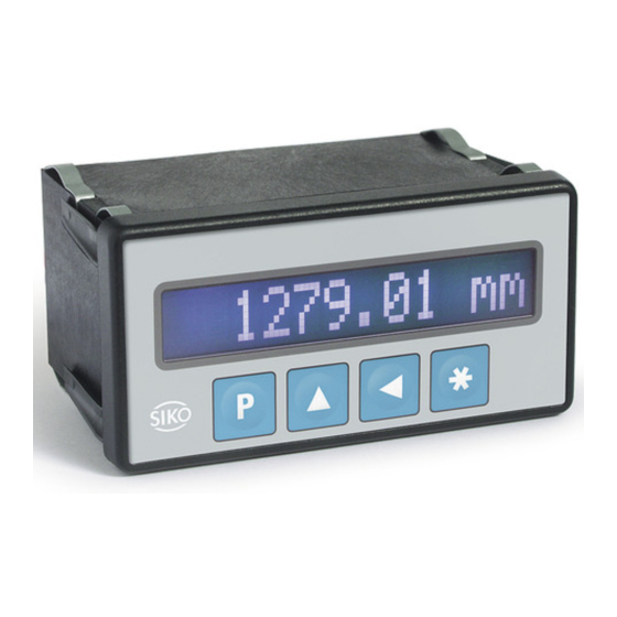
Summary of Contents for Siko MA100/2
- Page 1 MA100/2 Magnetbandanzeige Deutsch Originalmontageanleitung Seite 2 Magnetic Display English Translation of the Original Installation Instructions page 11 172/19...
-
Page 2: Table Of Contents
2.4 Grundlegende Sicherheitshinweise 3 Identifikation 4 Installation 4.1 Mechanische Montage 4.2 Elektrische Installation 4.3 Option Schaltausgänge 5 Inbetriebnahme 6 Transport, Lagerung, Wartung und Entsorgung 7 Zubehör Tischgehäuse 8 Technische Daten MA100/2 · Datum 03.09.2019 · Art. Nr. 82096 · Änd. Stand 172/19... -
Page 3: Dokumentation
Todesfolge, Sachschäden oder ungeplanten Gerätereaktionen führen können, sofern Sie die gegebenen Anweisungen missachten. Gefährdungen, die zu schweren Körperverletzungen, Sachschäden oder WARNUNG ungeplanten Gerätereaktionen führen können, sofern Sie die gegebenen Anweisungen missachten. MA100/2 · Datum 03.09.2019 · Art. Nr. 82096 · Änd. Stand 172/19... -
Page 4: Zielgruppe
Geräte/Systeme gemäß den Standards der Sicherheitstech- nik in Betrieb zu nehmen, zu erden und zu kennzeichnen. 2.4 Grundlegende Sicherheitshinweise Explosionsgefahr GEFAHR ` Magnetbandanzeige nicht in explosionsgefährdeten Zonen einsetzen. MA100/2 · Datum 03.09.2019 · Art. Nr. 82096 · Änd. Stand 172/19... -
Page 5: Identifikation
Gehäuse lose halten. 2. Die seitliche Zentrierung leicht andrücken und das Gehäuse in den Ausschnitt schieben bis die Panel-Clips vollständig einrasten. Schalttafelausschnitt Panel-Clip Zentrierung Abb. 1: Einbau MA100/2 · Datum 03.09.2019 · Art. Nr. 82096 · Änd. Stand 172/19... -
Page 6: Elektrische Installation
Der Anschluss erfolgt über die 6-polige Mini-Din Buchse an der Rückseite Abb. (siehe Anschlussbelegung Einbaugehäuse EG Abb. • 9 pol. Steckleiste (siehe Sensor Litzenquerschnitt ≤2.5 mm² PE Anschluss für Flachsteckhülse Abb. 2: Anschluss MA100/2 · Datum 03.09.2019 · Art. Nr. 82096 · Änd. Stand 172/19... -
Page 7: Option Schaltausgänge
Es stehen zwei Open-Kollektor Ausgänge (A1, A2) zur Verfügung. A2 = UGW A1 = OGW A2 A1 max. 30 V DC max. 100 mA Abb. 4: Anschlussschema Option Schaltausgänge MA100/2 · Datum 03.09.2019 · Art. Nr. 82096 · Änd. Stand 172/19... -
Page 8: Inbetriebnahme
• Anschlüsse weder durch mechanische noch durch thermische Einflüsse beschädigen. • Vor Montage ist die Mangetbandanzeige auf Transportschäden zu untersuchen. Beschädigte Mangetbandanzeigen nicht einbauen. Wartung Bei korrektem Einbau nach Kapitel ist die Mangetbandanzeige wartungs- frei. MA100/2 · Datum 03.09.2019 · Art. Nr. 82096 · Änd. Stand 172/19... -
Page 9: Zubehör Tischgehäuse
+0.6 Gewicht ~0.2 kg 24 V DC ~0.5 kg 230 V AC / 115 V AC Elektrische Daten Ergänzung Betriebsspannung 24 V DC ±20 % 115 V AC ±10 % 230 V AC ±10 % Stromaufnahme 70 mA bei 24 V DC 20 mA bei 115 V AC 10 mA bei 230 V AC MA100/2 · Datum 03.09.2019 · Art. Nr. 82096 · Änd. Stand 172/19... - Page 10 Luftfeuchtigkeit ≤95 % Betauung nicht zulässig EN 61000-6-2 Störfestigkeit / Immission EN 61000-6-4 Störaussendung / Emission Schutzart IP40 Gesamtgerät EN 60529 IP60 frontseitig bei Schaltta- EN 60529 feleinbau MA100/2 · Datum 03.09.2019 · Art. Nr. 82096 · Änd. Stand 172/19...
- Page 11 3 Identification 4 Installation 4.1 Mechanical mounting 4.2 Electrical Installation 4.3 Switching output option 5 Commissioning 6 Transport, Storage, Maintenance and Disposal 7 Accessory benchtop housing 8 Technical data MA100/2 · Date 03.09.2019 · Art. No. 82096 · Mod. status 172/19...
-
Page 12: Documentation
Danger that may cause minor injury, property damage or unplanned device CAUTION reactions if you disregard the instructions given. MA100/2 · Date 03.09.2019 · Art. No. 82096 · Mod. status 172/19... -
Page 13: Target Group
Please check the particular type of unit and type number from the identifi- cation plate. Type number and the corresponding version are indicated in the delivery documentation. e. g. MA100/2 0023 version number type of unit MA100/2 · Date 03.09.2019 · Art. No. 82096 · Mod. status 172/19... -
Page 14: Installation
` Use strands with suitable ferrules. ` Prior to switching on check all mains and plug connections. ` Switch on operating voltage together with downstream electronics (e. g., control unit). MA100/2 · Date 03.09.2019 · Art. No. 82096 · Mod. status 172/19... - Page 15 PE tag for connec- tion Fig. 2: Connection RS232 RS485 switching output Fig. 3: Connection diagram MA100/2 · Date 03.09.2019 · Art. No. 82096 · Mod. status 172/19...
-
Page 16: Switching Output Option
When the unit is correctly connected and switched on: • hardware version (e. g. "SIKO:MA100/2") approx. 1.5 s • firmware version (e. g. V1.00) Subsequently the specific parameters of the machine can be programmed. MA100/2 · Date 03.09.2019 · Art. No. 82096 · Mod. status 172/19... -
Page 17: Transport, Storage, Maintenance And Disposal
Therefore, the magnetic display must be recycled after it has been taken out of operation ultimately. Observe the environment protec- tion guidelines of your country. MA100/2 · Date 03.09.2019 · Art. No. 82096 · Mod. status 172/19... -
Page 18: Accessory Benchtop Housing
2x 30 V ≤100 mA Interface without, RS232, RS485 Type of connection terminal strip 9 pole (supply, switching output, interface/reference switch) Mini-DIN 6 pole, 1x socket (Sensor MS100/1) MA100/2 · Date 03.09.2019 · Art. No. 82096 · Mod. status 172/19... - Page 19 / immis- sion EN 61000-6-4 emitted interference / emission Protection category IP40 complete equipment EN 60529 IP60 front panel, when built EN 60529 into a control panel MA100/2 · Date 03.09.2019 · Art. No. 82096 · Mod. status 172/19...
- Page 20 SIKO GmbH Weihermattenweg 2 79256 Buchenbach Telefon/Phone + 49 7661 394-0 Telefax/Fax + 49 7661 394-388 E-Mail info@siko-global.com Internet www.siko-global.com Service support@siko-global.com...


Need help?
Do you have a question about the MA100/2 and is the answer not in the manual?
Questions and answers