
Subscribe to Our Youtube Channel
Related Manuals for Siko MA10/4


Summary of Contents for Siko MA10/4
- Page 1 MA10/4 Messanzeige Deutsch Originalmontageanleitung Seite 2 Electronic Display English Translation of the Original Installation Instructions page 14 157/17...
-
Page 2: Table Of Contents
4.1 Mechanische Montage 4.2 Elektrische Installation 4.3 Option serielle Schnittstelle RS232 oder RS485 4.4 Option Schaltausgänge 5 Inbetriebnahme 6 Transport, Lagerung, Wartung und Entsorgung 7 Zubehör Tischgehäuse 8 Technische Daten MA10/4 · Datum 15.05.2017 · Art. Nr. 82316 · Änd. Stand 157/17... -
Page 3: Dokumentation
3. Eigenmächtige Umbauten und Veränderungen an der Messanzeige sind verboten. 4. Die vorgeschriebenen Betriebs- und Installationsbedingungen sind einzuhalten. 5. Die Messanzeige darf nur innerhalb der technischen Daten und der angegebenen Grenzen betrieben werden (siehe Kapitel 8). MA10/4 · Datum 15.05.2017 · Art. Nr. 82316 · Änd. Stand 157/17... -
Page 4: Kennzeichnung Von Gefahren Und Hinweisen
` Projektierung, Inbetriebnahme, Montage und Wartung nur durch geschultes Fachpersonal. ` Dieses Personal muss in der Lage sein, Gefahren, welche durch die mechanische, elektrische oder elektronische Ausrüstung verursacht werden können, zu erkennen. MA10/4 · Datum 15.05.2017 · Art. Nr. 82316 · Änd. Stand 157/17... -
Page 5: Grundlegende Sicherheitshinweise
1. Gerät in Schalttafelausschnitt schieben bis die Panel-Clips Gehäuse lose halten. 2. Die seitliche Zentrierung leicht andrücken und das Gehäuse in den Ausschnitt schieben bis die Panel-Clips vollständig einrasten. MA10/4 · Datum 15.05.2017 · Art. Nr. 82316 · Änd. Stand 157/17... -
Page 6: Elektrische Installation
5 (GND) bzw. 14 (Geberversorgung +) und 18 (GND). Die Spannung beträgt abhängig von der Geräteausführung 24 V DC oder 5 V DC. In beiden Varian- ten kann ein Strom von ≤200 mA entnommen werden. MA10/4 · Datum 15.05.2017 · Art. Nr. 82316 · Änd. Stand 157/17... - Page 7 Der Anschluss des Referenzpunktgebers erfolgt an Klemme 7 (RFS/CAL) und Klemme 9 (GND). Hilfsspannungsausgang An Klemme 6 steht unabhängig von der Art der Versorgung der MA10/4 eine Spannung von 24 V DC/≤50 mA zur Versorgung von z. B. Näherungs- schaltern zur Verfügung. Anschlussbelegung • 1x 13 pol.
- Page 8 SSI-Geber z. B. Winkelkodierer Kalibrier- schalter MSA510 Schirm Abb. 5: Anschlussschema Absolut SSI MA10/4 · Datum 15.05.2017 · Art. Nr. 82316 · Änd. Stand 157/17...
- Page 9 Abb. 7: Anschlussschema Drehzahl Zulässige Leistungsaufnahme Die Versorgung für die Messanzeige ist ausreichend zu dimensionieren. Die ACHTUNG Spannungswerte sind den technischen Daten in Kapitel zu entnehmen. MA10/4 · Datum 15.05.2017 · Art. Nr. 82316 · Änd. Stand 157/17...
-
Page 10: Option Serielle Schnittstelle Rs232 Oder Rs485
• Positionswert ≤ unterer Grenzwert (UGW): Aktor 2 aktiv Aktor 2 Aktor 1 Belegung Klemmleiste Abb. 10: Anschlussschema Option Schaltausgänge MA10/4 · Datum 15.05.2017 · Art. Nr. 82316 · Änd. Stand 157/17... -
Page 11: Inbetriebnahme
Stoffe und sind zugleich Wertstoffträger. Die Messanzeige muss des- halb nach seiner endgültigen Stilllegung einem Recycling zugeführt wer- den. Die Umweltrichtlinien des jeweiligen Landes müssen hierzu beach- tet werden. MA10/4 · Datum 15.05.2017 · Art. Nr. 82316 · Änd. Stand 157/17... -
Page 12: Zubehör Tischgehäuse
24 V AC ±10 % 115 V AC ±10 % 230 V AC ±10 % 15 V AC ±10 % Stromaufnahme 120 mA bei 24 V DC, ohne Geber Leistungsaufnahme <9 VA Geberversorgung 24 V DC (200 mA) 5 V DC (200 mA) Eingänge Referenzschalter Hilfsspannung 24 V DC ≤50 mA Gebereingangsfrequenz ≤500 kHz MA10/4 · Datum 15.05.2017 · Art. Nr. 82316 · Änd. Stand 157/17... - Page 13 -20 ... 85 °C relative Luftfeuchtigkeit Betauung nicht zulässig EN 61000-6-2 Störfestigkeit / Immission EN 61000-6-4 Störaussendung / Emission Schutzart IP40 Gesamtgerät EN 60529 IP60 frontseitig bei Schaltta- EN 60529 feleinbau MA10/4 · Datum 15.05.2017 · Art. Nr. 82316 · Änd. Stand 157/17...
- Page 14 4.2 Electrical Installation 4.3 Optional serial RS232 or RS485 interface 4.4 Switching output option 5 Commissioning 6 Transport, Storage, Maintenance and Disposal 7 Accessory benchtop housing 8 Technical data MA10/4 · Date 15.05.2017 · Art. No. 82316 · Mod. status 157/17...
-
Page 15: Safety Information
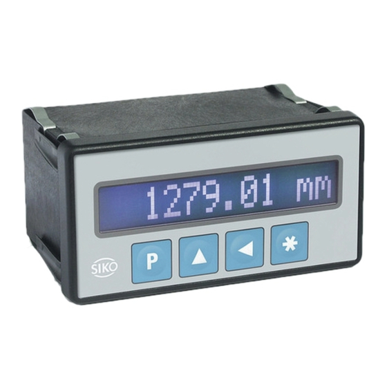
2 Safety information 2.1 Intended use The MA10/4 display is an electronic display. The display is designed to serve different applications depending on its version: • Incremental: Combined with an incremental encoder the display rep- resents an electronic measuring or display system for distance and angle measurement. -
Page 16: Identification Of Dangers And Notes
• are familiar with the safety guidelines of the electrical and automation technologies when performing configuration tasks; • are authorized to commission, earth and label circuits and devices/ systems in accordance with the safety standards. MA10/4 · Date 15.05.2017 · Art. No. 82316 · Mod. status 157/17... -
Page 17: Basic Safety Information
2. Press the lateral centering slightly down and push the housing into the cut-out until the panel clips snap completely. Panel cut-out Panel clip Centering Fig. 1: Installation MA10/4 · Date 15.05.2017 · Art. No. 82316 · Mod. status 157/17... -
Page 18: Electrical Installation
9 (GND). Output of auxiliary voltage Terminal 6 supplies a voltage of 24 V DC/≤50 mA for supplying of proximity switches e. g., independent of the way the MA10/4 is supplied. MA10/4 · Date 15.05.2017 · Art. No. 82316 · Mod. status 157/17... - Page 19 PP (push-pull) reference OC (open collector) switch OP (push pull) screen Fig. 4: Connection diagram incremental MA10/4 · Date 15.05.2017 · Art. No. 82316 · Mod. status 157/17...
- Page 20 PP (push-pull) switch OC (open collector) screen Fig. 6: Connection diagram number of pieces MA10/4 · Date 15.05.2017 · Art. No. 82316 · Mod. status 157/17...
-
Page 21: Optional Serial Rs232 Or Rs485 Interface
(GND), 22 (TXD/ DÜA) and 23 (RXD/ DÜB). Designation terminal Fig. 8: Connection diagram RS232 interface option MA10/4 · Date 15.05.2017 · Art. No. 82316 · Mod. status 157/17... -
Page 22: Switching Output Option
• Position value ≤ lower limiting value (LOL): actuator 2 active actuator actuator Designation terminal Fig. 10: Connection diagram switching outputs MA10/4 · Date 15.05.2017 · Art. No. 82316 · Mod. status 157/17... -
Page 23: Commissioning
Therefore, the electronic display must be recycled after it has been taken out of operation ultimately. Observe the environment protec- tion guidelines of your country. MA10/4 · Date 15.05.2017 · Art. No. 82316 · Mod. status 157/17... -
Page 24: Accessory Benchtop Housing
Current consumtion 120 mA at 24 V DC, without encoder Power input <9 VA Encoder supply 24 V DC (200 mA) 5 V DC (200 mA) Inputs reference switch auxiliary voltage 24 V DC ≤50 mA Encoder input frequency ≤500 kHz MA10/4 · Date 15.05.2017 · Art. No. 82316 · Mod. status 157/17... - Page 25 / immis- sion EN 61000-6-4 emitted interference / emission Protection category IP40 complete equipment EN 60529 IP60 front panel, when built EN 60529 into a control panel MA10/4 · Date 15.05.2017 · Art. No. 82316 · Mod. status 157/17...
- Page 26 MA10/4...
- Page 27 MA10/4...
- Page 28 SIKO GmbH Weihermattenweg 2 79256 Buchenbach Telefon/Phone + 49 7661 394-0 Telefax/Fax + 49 7661 394-388 E-Mail info@siko.de Internet www.siko-global.com Service support@siko.de...
Need help?
Do you have a question about the MA10/4 and is the answer not in the manual?
Questions and answers