Table of Contents

Advertisement

O 6 D / E A P P L I C A T I O N G U I D E

Advertisement

Table of Contents
loading

Summary of Contents for Carlyle 06D Series

  • Page 1 O 6 D / E A P P L I C A T I O N G U I D E...
  • Page 2: Table Of Contents

    TABLE OF CONTENTS General Information..........2 4.0 Compressor Features and Accessories.....25 Features of Carlyle 06D/E Compressors...........2 4.1 06D Compressor Motor Protection ........25 4.2 06E Compressor Motor Protection........26 06D/E Model Number Significance ..........4 4.3 Rated Load Amperes (RLA) and 06D/E Compressor Specification Tables ..........5 Maximum Continuous Current (MCC) .......30...
  • Page 3: General Information

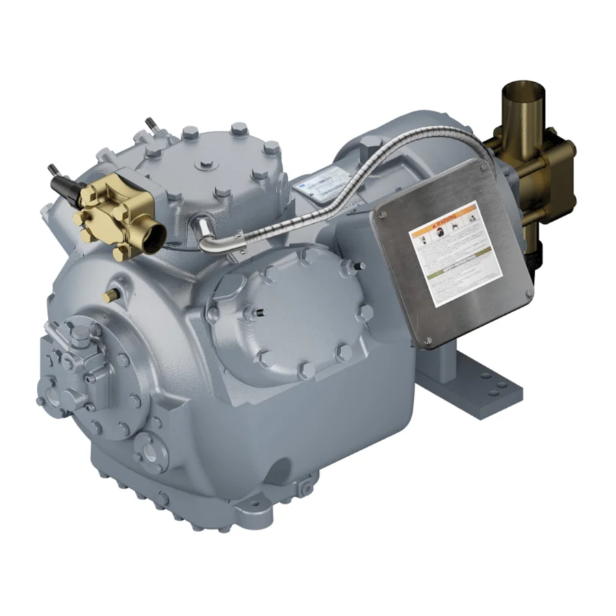
    General Information Features of Carlyle 06D/E Compressors Canted Discharge Valve Valve Plate Vented Connecting Hi-Lift Rods Discharge Valve Capacity Control System Contoured Pistons Automatic Reversible Oil Pump Crankcase Oil Heater Oversize Oil Sump Oil Filter Screen Oil Drain Assembly Connection...
  • Page 4 On start-up, oil level can temporarily drop too low, causing unnecessary wear in other compressor designs when on shut- down, the oil is diluted by refrigerant. The Carlyle oversize oil sump holds extra oil in crankcase to prevent normal oil migra- tion from dropping the oil level below the safe lubrication range.
  • Page 6: E Compressor Specification Tables

    06D/E Refrigeration Compressor Specifications...
  • Page 7: E Compressor Specifications (60 Hz Units)

    06D/E Compressor Specifications (60 Hz Units)
  • Page 8: E Compressor Specifications (50 Hz Units)

    06D/E Compressor Specifications (50 Hz Units)
  • Page 9: System Design Considerations

    0°F (0°C) subcooling. saturated suction and saturated condensing conditions. This includes refrigerants such as R-12, R-22, R-502, Note: Some Carlyle air conditioning ratings are at ARI R-134a and R-404A. Some refrigerants are a mixture (Air Conditioning & Refrigeration Institution) rating con- and have a different saturated temperature as a vapor ditions and with 15°F subcooling.
  • Page 10 MEDIUM TEMPERATURE temperature. When in the liquid state the refrigerant is Refrigerant Saturated Saturated referred to as the saturated bubble temperature. Carlyle’s Suction Condensing 06D and 06E compressor performance data with R-407C Temperature Temperature is based on the compressor suction and discharge at the saturated dew pressures.
  • Page 11: Refrigerant Piping

    Compressors applied ommended. Because oil dilution is more critical with in spring-mounted systems should also have adequate HFC refrigerants and POE lubricants, Carlyle requires the flexibility in the suction and discharge piping to avoid...
  • Page 12: Proper Compressor Control And Protection

    For drier core or dehydrating the system, can prevent seri- that reason Carlyle does not recommend more than 12 ous compressor damage. starts per hour for these semi-hermetic compressors.
  • Page 13: Compressor Interconnection

    Several manufacturers supply this type of RECOMMENDED oil management system. It is important that floats are Figure 1 – Suction Piping properly selected for Carlyle’s 06D and 06E compres- sors. For the 06D compressor, a special adapter is...
  • Page 14 1/8 to 3/8 up the sightglass. One of Carlyle’s major concerns on multiple 06E com- pressor applications is to avoid accumulating large quantities of oil in “off” compressors. To minimize this potential problem, Carlyle recommends the oil levels be kept at a 1/8 to 3/8 sightglass level.
  • Page 15: Motor-Compressor Selection

    The outdoor use, and are UL recognized as “Equal Alternate” mechanical design of Carlyle 06D and 06E semi-hermet- to all caulked boxes previously used. Drawn steel boxes ic compressors provides for exclusion from the scope of...
  • Page 16: Compressor Lubrication System

    2.0 Compressor Lubrication System 2.1 Compressor Lubrication running gear are producing the windage required to push the oil down on one side while raising it on the All refrigeration compressors must have adequate lubri- other. Reversing the direction of rotation of the motor cation to ensure trouble-free operation and a long life.
  • Page 17: The Oil Pump

    When additional oil or a complete oil change is To check for excessive system oil charges in 06E com- required, use only the listed Carlyle approved oils. pressors, it is recommended that the oil levels of the compressors in the system be brought down to approxi- For CFC and HCFC refrigerants use: mately 1/4 of the sightglass.
  • Page 18: E Oil Pressure History

    †Medium temperature applications only. applications. The regulator may require replacement in Carlyle does not recommend the use of POE lubricants with R-22. 06D A/C models if applied with variable speed. Review Carlyle Bulletin 95T-8 for modification recommenda- 2.4 06D/E Oil Pressure History...
  • Page 19: Capacity Control

    Figure 10. All 6-cylinder 06D and 06E compressors can be unloaded at all condensing temperatures below Carlyle’s compressor suction cut-off capacity control sys- 120°F (49°C) with 1 bank of capacity control. Do not tem has been approved for R-502, R-404A, and R-507 unload more than 1 bank on 6-cylinder 06D or 06E applications down to -40°F (-40°C) suction and for...
  • Page 20: Pump-Down Control

    (60) sure may be enough to load the compressor back-up. (54) For this reason, Carlyle recommends a minimum differ- ential setting of 6 to 10 psi (.4 to .7 bar). The final set- (49) ting should be evaluated for the final application because...
  • Page 21: Part Load Performance Factors

    Table 3 below. The factors can be applied to and will not function on the center cylinder head of any the full load published Carlyle capacity and power data 06D or 06E 6-cylinder compressor. This unloader can- for all refrigerants and conditions. The system designer not be installed on Carlyle’s 2-cylinder 06D models.
  • Page 22: Pressure Differential Required To Load Compressor

    When the solenoid is de-energized, the valve Suction cut-off unloading is an option for all four and six loads the cylinder bank (2 cylinders) as shown in cylinder Carlyle 06D/E compressors. The capacity con- Figure 12. trol operation and application requirements are found in the System Design section (Section 1.0) of this manual...
  • Page 23: Suction Pressure Capacity Control Operation

    UNLOADER UNLOADER UNLOADER COIL PISTON HEAD VALVE ENERGIZED ASSEMBLY BODY SOLENOID VALVE UNLOADER ASSY VALVE SPRING COVER BLEED PLATE ORIFICE STRAINER VALVE PLATE PRESSURE PISTON SUCTION SUCTION DISCHARGE DISCHARGE SUCTION MANIFOLD MANIFOLD DISCHARGE VALVE VALVE Figure 13 – Electric Unloaded Operation As reduced capacity is desired an external controller With the poppet valve closed, discharge gas is directed energizes the solenoid coil.
  • Page 24 Figure 12A – Pressure Loaded Operation Figure 13A – Pressure Unloaded Operation 150 PSI (10.4 BAR) SYSTEM DIFFERENTIAL (7.2) LOAD UP PRESSURE VS NO. OF TURNS (6.5) (5.8) (5.2) (4.5) (3.8) (3.1) DOTTED LINES INDICATE EXPECTED (2.4) TOLERANCE EXTREMES UNDER NORMAL R-22 OPERATING CONDITIONS (1.7) (1.0)
  • Page 25: Pressure Actuated Capacity Control Adjustment

    BODY tioning models may require modification of the internal lubrication system to operate properly. The changes required for the 06D A/C models are noted in Carlyle Pressure Actuated Unloader Valve Bulletin 95T-8 or contact Carlyle Application Engineering if additional clarification is required. VFD’s, when prop- 3.11 Pressure Actuated Capacity Control...
  • Page 26: Compressor Features And Accessories

    4.0 Compressor Features and Accessories 4.1 06D Compressor Motor Protection Primary Motor Protection The 06D compressors, when purchased with overloads Texas Instruments supplementary overloads are nor- installed in the compressor terminal box, are protected mally supplied with 06D compressors. These relays trip from motor overcurrent and overtemperature.
  • Page 27: Compressor Motor Protection

    2 to 6 seconds and the second 3 legs in 1 to 3 sec- or fuses should not be selected at trip settings less then onds. Carlyle recommends a 1 to 1.25 second time delay the MCC (Maximum Continuous Current) values shown between energizing the first and second legs.
  • Page 28 COMPRESSOR MOTOR DATA CIRCUIT BREAKER DATA MAX. RECOMMENDED MUST CIRCUIT LRA PW MUST MUST COMPRESSOR MAX. TRIP MAX. BREAKER (1ST HOLD TRIP RECOMM. AMPS PART NO. MODEL* VOLT WINDING) AMPS AMPS 06ER(1/4)50100 27.1 HH83XA460 33.5 23.9 (1/4)50600 400/460 32.9 HH83XA463 33.9 22.0 (1/4)50300 208/230...
  • Page 29 COMPRESSOR MOTOR DATA CIRCUIT BREAKER DATA MAX. RECOMMENDED MUST CIRCUIT LRA PW MUST MUST COMPRESSOR MAX. TRIP MAX. BREAKER (1ST HOLD TRIP RECOMM. AMPS PART NO. MODEL* VOLT WINDING) AMPS AMPS 06EA(2/5)50100 32.1 HH83XA461 27.1 (2/5)50600 400/460 38.6 HH83XA424 35.0 25.3 (2/5)50300 208/230...
  • Page 30 Thermal Protection A discharge gas thermostat is supplied to provide overtemperature protection. These sensors are supplied with low and medium temperature 06ER and 06EM compressors. The sensor is factory installed into one cylinder head to sense discharge gas temperature. The sensor will open on temperature rise and close on tem- perature fall.
  • Page 31: Rated Load Amperes (Rla) And Maximum Continuous Current (Mcc)

    For that reason, Carlyle recom- condition representative of unit operation. In unitary mends the discharge temperature thermostat be wired equipment, that condition has been defined as the ARI into the control circuit in a manual reset mode.
  • Page 32: Compressor Mcc Values

    MCC value which Carlyle lists with UL. Therefore, Paragraph 440.52 of the National Electrical Code. Briefly, Carlyle will not be listing any MCC values with UL on any the National Electrical Code allows: of the 06E compressors. Carlyle does specify the maxi-...
  • Page 33: Compressors: Contactor Sizing And Wire Sizing

    The compressor nameplate specifies voltage, phase, fre- Wire Sizing quency, and locked rotor current. The rated load current On our larger 06E compressors, Carlyle requires that the shown in our specification charts may vary depending on equipment manufacturer utilize an approved and UL rec-...
  • Page 34: Compressor Features And Accessories

    5.1 Safety Relief Valves 5.3 Oil Safety Switch All 06E compressors are equipped with built-in safety Carlyle has approved the following oil safety switches for relief valves that are factory set to relieve from the dis- use with all 06D and 06E compressors: charge to the suction side of the compressor at a pres- sure differential of 400 psi (27 bar).
  • Page 35: Crankcase Heaters

    The use of an oil safety switch is recommended/required by Carlyle as noted below. TYPE OF USING 06D USING 06E SYSTEM COMPRESSORS COMPRESSORS Single Compressor Recommended Required without Unloading Single Compressor Recommended Required with Unloading Multiple Compressors Required Required without Unloading...
  • Page 36: Baffle Plates

    Also see Carlyle Bulletin 99T-4 for additional application information. Carlyle Baffle Plate Recommendations – Low and Medium Temperature Applications *These selections have changed. Carlyle Baffle Plate Recommendations – Medium and High Temperature Applications...
  • Page 37: Discharge Line Check Valves

    5.8 Suction Cut-Off Capacity Control Suction cut-off unloading is an option for all four and six cylinder Carlyle 06D/E compressors. The capacity con- trol operation and application requirements are found in the Section 1 of this manual and should be carefully Cylinder head cooling fans are required in certain low reviewed.
  • Page 38: Spring Mounting

    This design uses a flange nut that does not require welding. 5.11 Solid Mounting 5.13 Conduit Adapter Plates All 06D/E compressors may be solid mounted. Carlyle Electrical conduits are mounted to the 06E terminal box, offers the 30HR070-1071 solid spacer with four spacers by use of an adapter plate.
  • Page 39: Service Valves

    5.15 Service Valves 06D - SERVICE SHUT-OFF VALVES COMPRESSOR SUCTION VALVE ODF (INCHES) DISCHARGE VALVE ODF (INCHES) SELECTION 06DR109 06DA660061 06DA660060 Standard (3ø only) 06DM808 06DA660060 06DA660061 Optional 06DR109 06DA660062 06DA660060 Standard (1ø only) 06DM808 06DA660064 1-1/8 06DA660061 Optional 06DR013 06DA660064 1-1/8 06DA660060...
  • Page 40: Appendix A: Compressor Outline Drawings

    Appendix A: Compressor Outline Drawings Model Compressor Application Page 06DR109 Low Temperature 06DM808 & 06DA808 Medium & High Temperature 06DR013 Low Temperature 41, 42 06DR316 Low Temperature 41, 42 06DM313 & 06DA313 Medium & High Temperature 43, 44 06DM316 Medium Temperature 43, 44 06DR718 Low Temperature...
  • Page 41: Outline Drawings

    06D Low Temperature Compressors 17.93 3/8-16 x 7/8 LG 2.01 CAPSCREW = CUSTOMER SUPPLIED LOCKWASHER PLATEWASHER SPRING CUP COMPRESSOR FOOT 1.25 WELD 45° MOTOR END AND (TYP.) PUMP END (TYP.) .623 DIA. (TYP.) .627 14.97 14.86 SPRING MOUNTING ARRANGEMENT 3.69 3.75 5.52 2.91...
  • Page 72 P.O. Box 4808 • Syracuse, New York 13221 Rev B 6/04 change at any time, specifications or designs and In USA & Puerto Rico 1-800-GO-CARLYLE • In Canada 1-800-258-1123 • In Mexico: 95-800-GO-CARLYLE prices without notice and without incurring obligations.

Table of Contents