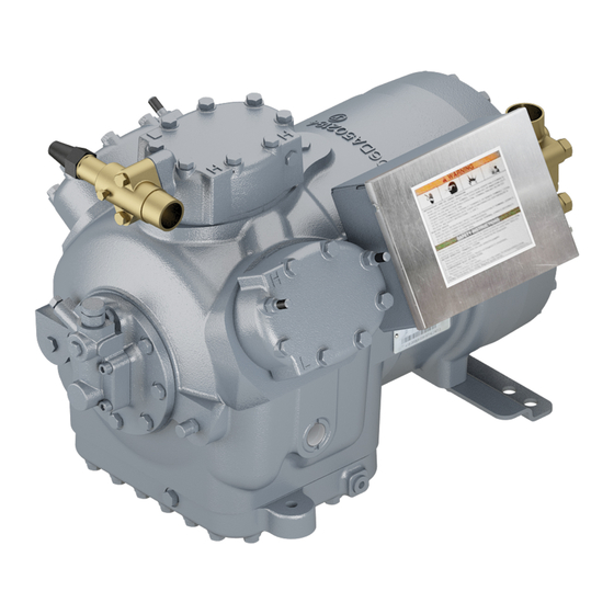
Carlyle 06D Installation Instructions Manual
Semi-hermetic reciprocating compressor
Hide thumbs
Also See for 06D:
- Service manual (167 pages) ,
- Application manual (72 pages) ,
- Installation and start-up instructions (4 pages)
Table of Contents
Advertisement
Quick Links
Download this manual
See also:
Service Manual
GENERAL
1. Inspect compressor for shipping damage and file claim
with shipping company if damaged or incomplete.
2. Check compressor nameplate for correct model and
voltage designation.
3. Before installation, review all Carlyle compressor appli-
cation literature to assure yourself that the proper com-
pressor has been selected and is being applied in a
proper manner. The required application literature is
available through Carlyle.
SAFETY INSTRUCTIONS
DANGER
Failure to follow these instructions will result in severe
personal injury or death.
ELECTRIC SHOCK HAZARD. Do not operate compres-
sor or provide electric power to it unless the compressor
terminal box is installed and the terminal box cover is in
place and secured.
DO NOT provide power to unit or turn on compressor un-
less suction and discharge service valves are open.
DO NOT remove the compressor terminal box cover until
all electrical sources have been disconnected.
DO NOT USE oxygen or other industrial gases for tight-
ness/pressure testing. Use nitrogen or inert gas.
WARNING
Failure to follow these instructions may result in serious
injury or death.
CONTENTS UNDER PRESSURE.
tains oil and refrigerant under pressure. Pressure must
be relieved before installation, servicing or opening any
connections.
HOT and COLD surface temperatures can occur during
operation and can result in severe burns or frostbite.
USE ONLY approved refrigerants and refrigeration oils.
NEVER EXCEED specified test pressures.
strength/tightness test pressure may not exceed the
compressor maximum Test pressure on the Nameplate.
Close shutoff valves to isolate compressor if necessary.
CHECK THE REFRIGERANT TYPE. Charge only with
refrigerant that conforms to AHRI Standard 700.
Only qualified, authorized, and appropriately trained HVAC
or refrigeration personnel, should install, commission, and
maintain this equipment.
Use appropriate personal safety equipment where required.
Safety goggles, gloves, protective clothing, safety boots, and
hard hats should be worn where necessary.
OPERATING LIMITS: Refer To Application
Guide
GENERAL INSTALLATION PROCEDURES
Holding Charge
Compressor is factory supplied with a 7 to 20 psig (0.5 to
1.4 bar) charge of dry air or nitrogen. This internal pressure
Installation
Instructions
Compressor con-
System
must be relieved before attempting to remove any compres-
sor fitting or part.
Relieve holding charge by removing the cap on the low pres-
sure connection fitting and depressing the internal disc. See
Fig. 1 through 4 for applicable low pressure connection fit-
ting location.
Service Valves
Remove valve pads and attach factory-supplied suction and
discharge gaskets and service valves to the compressor.
5
Torque
/
-in. -18 mounting bolts 20 to 25 lb-ft (27 to
16
1
34 Nm) and
/
-in. -13 mounting bolts 80 to 90 lb-ft (109 to
2
122 Nm). When brazing piping to valve, wrap the valve in a
wet cloth to prevent heat damage.
Oil
1. Check to see that oil level is
compressor sight glass before starting and after 15 to
20 minutes of operation. Compressors may be shipped
with or without an oil charge based on model. All com-
pressors must contain the specified oil charge prior to
start-up as a condition of warranty.
2. To add oil: Relieve internal crankcase pressure, isolate
crankcase, and add oil through the oil fill connection
(see Fig. 1 through 4). To remove excess oil: Reduce
internal crankcase pressure to 2 psig (1.15 bar), isolate
crankcase, then loosen the oil drain plug allowing oil to
seep out past the threads of the plug.
CAUTION
With the compressor crankcase under slight pressure, do
not remove the oil drain plug as the entire oil charge
could be lost. Do not reuse drained oil or oil that has
been exposed to the atmosphere.
3. When additional oil or a complete oil change is re-
quired, use only the listed Carlyle approved oils.
For CFC and HCFC refrigerants use:
Manufacturer
Totaline
Witco Suniso
Shrieve Chemical
Texaco Ind.
IGI Petroleum Ind.
For HFC refrigerants use:
Manufacturer
ICI EMKARATE
Lubrizol Lubrikuhl*
Mobil Arctic†
Castrol†
Castrol
Totaline
*Lubrizol ISO 68, also sold under Texaco Capella HFC
68NA brand.
†Medium and high temperature applications only.
06D
1
3
/
to
/
of the way up on
4
4
Brand Name
150
3GS
Zerol 150
WFI-32-150
Cryol-150
Brand Name
RL68H
2916S
EAL 68
SW 68
E 68
P903-1701
Advertisement
Table of Contents

Related Manuals for Carlyle 06D


Summary of Contents for Carlyle 06D
- Page 1 Fig. 1 through 4 for applicable low pressure connection fit- voltage designation. ting location. 3. Before installation, review all Carlyle compressor appli- cation literature to assure yourself that the proper com- Service Valves pressor has been selected and is being applied in a Remove valve pads and attach factory-supplied suction and proper manner.
- Page 2 OIL DRAIN BOTTOM COVER CONNECTION (NOT SHOWN) Fig. 4 — 06D 6-Cylinder Compressors Fig. 1 — 06D 2-Cylinder Compressors 8 and 9 CFM 24/25, 28, 37 and 41 CFM (0.68, 0.79, 1.05 and (0.23 and 0.25 m /min) 1.16 m...
- Page 3 Each terminal plate assembly may be utilized with or without overloads. For compressors without overloads, please be sure adequate protection is supplied for all 3 phases of the motor in the form of a circuit breaker or similar system. For compressors with overloads, please refer to Table 2 and referenced figures to ensure proper connection with the ap- plicable overload system on the compressor.
- Page 4 Service Hybrid Overload Wiring — 5-Pin Plate Assembly or 6-Pin Plate Assembly for Univer- sal Compressor 1. Connect one control circuit lead to module connection CUSTOMER WIRING 11 located on top of the module as shown in Fig. 10. ROUTED THROUGH Use a fork terminal or stripped and tinned wire to pre- THE CT vent fraying.
- Page 5 connect flag terminals are securely and firmly fastened Bi-Metal Overload Wiring 5-Pin Plate — to the overload terminal tabs. Assembly or 6-Pin Plate Assembly for Univer- 3. When attaching power leads to the overloads requiring sal Compressor the ring terminals as noted above, use the hardware in 1.
- Page 6 Bi-Metal Overload Wiring — 6-Pin Plate NO. 10-32 SCREW Assembly for Part-Wind Compressor (B or D in digit 10 of the Manufacturing Model Number) 1. Connect one control circuit lead to the empty side tab LOCKWASHER #1 terminal location of the bottom overload, as shown in Fig.
- Page 7 See Fig. 1 through 4 for oil pressure safety switch connections. 2. Normal net oil pressure for 06D compressors is 18 to 34 psi (1.2 to 2.3 bar) above suction pressure. Net oil pressure may vary depending on the lubricant type ap- plied and operating conditions.
- Page 8 Lit. No. 574-067 CARLYLE COMPRESSOR DIVISION • © CARRIER CORPORATION Manufacturer reserves the right to discontinue, or change P.O. Box 4808 • Syracuse, New York 13221 Rev. E 12/15 at any time, specifications or designs without notice and Phone: In U.S. and Puerto Rico: 1-800-GO-CARLYLE Replaces: 06DA603632 without incurring obligations.
Need help?
Do you have a question about the 06D and is the answer not in the manual?
Questions and answers