Table of Contents
Advertisement
Advertisement
Table of Contents

Subscribe to Our Youtube Channel
Related Manuals for Carlyle TS Series


Summary of Contents for Carlyle TS Series
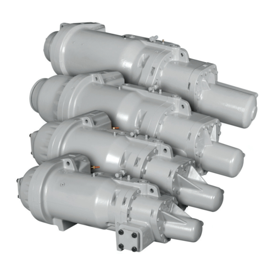
- Page 1 ® 06TS,TT,TU,TV CARLYLE PARAGON TWIN SCREW COMPRESSOR APPLICATION GUIDE a06-1663...
-
Page 2: Table Of Contents
Contents Introduction 4.2 Oil Separator Recommendations ..24 4.3 Oil Heater Recommendations... . .23 R-134a, R-513A, R-1234ze Applications ..3 4.4 Oil Level Safety Switch . -
Page 3: R-134A, R-513A, R-1234Ze Applications
R or M in the fifth digit of the model number). sor product line, which is comprised of four unique com- pressor families (series type TS, TT, TU, and TV). Carlyle UL File #: SA4936 CSA File #: SA4936 offers distinct versions of the Paragon Twin-Screw Com- For the UL and CSA approvals it is essential that only pressors for Low/Medium/High Temperature applications. -
Page 4: Compressor Displacement (Low/Medium Temperature Models). R-404A, R-407A, R-407C, R-407F, R-448A, R-449A, And R-507A
Compressor Displacement (Low/Medium Suction and Economizer Screens Temperature Models). R-404A, R-407A, R-407C, To increase the reliability of the compressor, a screen has R-407F, R-448A, R-449A, and R-507A been incorporated as a standard feature into the suction inlet and economizer inlet of the compressor. The suction See Tables 3 and 4. -
Page 5: Model Number Significance Chart
Model Number Significance Chart DIGIT MODEL NO. PACKAGE / ACCS. & 2 DESIGN FEATURE Not Used Semi-Hermetic Not Used Plate Mounting Feet Bar Mounting Feet & 4 MODEL CODE Paragon Paragon DESIGN LEVEL Paragon Phase 1 Paragon Product Variant Not Used DESIGN VARIABLE Air Cooled Vi MOTOR SIZE... -
Page 6: Compressor Physical Data And Connections
Compressor Physical Data and Connections Fig. 1 — 06TS Compressor Physical Data and Connections... -
Page 7: 06Tt Compressor
Compressor Physical Data and Connections (cont) Fig. 2 — 06TT Compressor Physical Data and Connections... -
Page 8: 06Tu Compressor
Compressor Physical Data and Connections (cont) a06-1666 Fig. 3 — 06TU Compressor Physical Data and Connections... -
Page 9: 06Tv Compressor
Compressor Physical Data and Connections (cont) OIL SUPPLY TO DISCHARGE FLANGE SUCTION TEMP WELL CAPACITY CONTROL 1/4 INCH SAE 3/8 ORIFICE SUCTION FLANGE OIL INLET PORT 5/8 ORIFICE OIL PRESSURE PORT ECONOMIZER FLANGE 3/8 INCH SAE HIGH SIDE LIFTING TEMP WELL LOCATIONS 1/4 INCH SAE CAPACITY CONTROL SOLENOIDS... -
Page 10: Medium/High Temperature
1.0 Medium/High Temperature System Design Considerations (R-134a, R-513A, R-1234ze) 1.1 Refrigerants and Lubricants Terminal Pin Dielectric Grease Carlyle recommends that compressor motor terminal Approved Refrigerants pins are coated with dielectric grease (P/N 06TT660050) The Paragon medium-temperature screw compressor is to reduce the effects of condensation that may form on specifically designed for use in R-134a systems. - Page 11 Fig. 5 — Operating Limits for Full Load Operation Paragon Operating Envelopes on R-134a, R-513A Saturated Suction Temperature (ºC) W/C Envelope TS3 A/C Max TS1 & TS2 A/C Max SDT A/C Envelope LEGEND A/C — Air-Cooled W/C — Water-Cooled Saturated Suction Temperature (ºF) Fig.
- Page 12 A/C — Air-Cooled Saturated Suction Temperature (ºF) W/C — Water-Cooled NOTE: Liquid injection may be required when operating fully unloaded. Contact Carlyle Applications Engineering for valve sizing requirements. Fig. 7 — Operating Limits for Unloaded Operation Start-Up and Suction Pressure Transients Outdoor Ambient Temperature [OAT] (ºC)
- Page 13 Carlyle recommends the following procedures: In order to eliminate the possibility of refrigerant migrat- ing into the oil separator and compressor, Carlyle 1. During initial run test of the unit, a suitable low- requires the application of a positive-seal, discharge...
-
Page 14: Control Points Summary
It is recommended that the compressor operate for 30 seconds fully unloaded prior to shut down. This ensures fully unloaded re-start will occur. NOTE: Carlyle offers Compressor Protection Module package, P/N 6BSB000472, which protects against reverse rotation, low oil flow and maximum discharge gas temperature. See Marketing Bulletin 14M-01 at www.carlylecompressor.com. -
Page 15: Medium/High Temperature System Oil Management
Carlyle recommends that the oil tempera- ture be monitored in warm climate applications and that Carlyle offers a Compressor Protection Module package... -
Page 16: Oil Level Safety Switch
200). particle size evaluated using ISO 16889 ( To reduce the possibility of false oil level alarms, Carlyle Filter areas must also be sufficient to avoid premature recommends that the oil level safety switch should be clogging of the filter during normal operation. -
Page 17: Low Temperature System Design Considerations
Carrier Part Number - 19XL680001 The Motor Cooling and Discharge Gas De-Superheating Terminal Pin Dielectric Grease lines are added to the envelopes to provide guidance for Carlyle recommends that compressor motor terminal OEM customers. pins are coated with dielectric grease, P/N 06TT660050,... - Page 18 Ra ng Point Liquid Injec on Mass Flow < 30% Suc on Mass Flow R-404A / R-507A Envelope Ra ng Point (-25 / 105) 50% Load Line Unloaded Motor Cooling Required in this Region -45° F Saturated Suc on Temperature Limit of R-407A, R407C, R407F, R448A, R449A Saturated Suction Temperature (ºF) Fig.
- Page 19 Saturated and discharge less than 0 psig (vacuum) for more than 1 minute after a Vapor maximum temps “cold” start. (Contact Carlyle Application Engineering for are met more information on cold starts.) Oil Supply at Refer to Fig. 13 140°F (60°C)
- Page 20 To minimize the possibility for reverse rotation exceed the recommended operating parameters. operation, Carlyle recommends the following procedures: Carlyle's solutions software can be used to estimate the 1. During initial run test of the unit, a suitable low-pres- discharge temperature for a given application. The oil...
- Page 21 Capacity Control/Slide Valve Control Please see Section 9.9.3 for de-superheating valve sizes Technical documentation for this Safety Control Module and part number information. package (P/N 6BSB000603) is provided on the Carlyle Website at www.carlylecompressor.com Fig. 15 — Refrigeration System Schematic...
-
Page 22: Control Points Summary
It is recommended that the compressor operate for 30 seconds fully unloaded prior to shut down. This ensures fully unloaded re-start will occur. NOTE: Carlyle offers Compressor Protection Module package, PN 6BSB000603, which protects against reverse rotation, low oil flow and maximum discharge gas temperature. See Marketing Bulletin 14M-01 at www.carlylecompressor.com. -
Page 23: Low Temperature System Oil Management
190°F (88°C), the heater element should be de- cation of this package provides equal alternate protection energized to prevent oil overheating. to the method described above. The Carlyle R-404A Figure 13 shows the minimum oil temperatures that must Compressor Protection Module package part number is be maintained when the compressor is not operating 6BSB000603. -
Page 24: Oil Filter
To reduce the possibility of false oil level alarms, Carlyle Carlyle's Solutions software calculates the oil cooler load recommends that the oil level safety switch should be based on the operating parameters and compressor open continuously for five seconds prior to initiating a models selected. -
Page 25: Oil Cooler Sizing
4.8 Oil Cooler Sizing An oil cooler is required for all LT and MT applications operating condition. Size the oil cooler by using Oil Cool- using R-404A, R-407A, R-407C, R-407F, and R-507A, ing Load featured in the Carwin software (see Fig. 17 and and may be required for R-134a, depending on the Table 9 below). - Page 26 Fig. 18 — Oil System Schematic...
-
Page 27: Unloader Operation
5.0 Unloader Operation All Paragon compressors come equipped with an • Part load is achieved by stopping the load or unload infinitely adjustable slide valve unloading system. The process previously described at an intermediate slide actual capacity reduction will depend on the system oper- valve position. -
Page 28: Approximate Part Load Factors
5.3.1 General Description 1. BACview is a registered trademark of Automated Logic Corporation. The Carlyle Control Module (CCM) will function to control 2. BACnet is a registered trademark of ASHRAE (American compressor capacity by operating the compressor's slide Society of Heating, Refrigeration and Air-Conditioning valve to maintain the system's control set point (suction Engineers). - Page 29 5.3.3 CCM Inputs/Outputs Software Version 1.5 Schematics Fig. 23 — CCM Inputs, Version 1.5 Fig. 24 — CCM Outputs, Version 1.5...
-
Page 30: Software Version 2.0 Schematics
5.3.4 CCM Inputs/Outputs Software Version 2.0 Schematics Fig. 25 — CCM Inputs, Version 2.0 Fig. 26 — CCM Outputs, Version 2.0... - Page 31 5.3.4 Slide Valve Capacity Control limits, the slide valve will not move, but remain fixed, keeping the compressor capacity constant. The CCM will have the ability to control the compressor slide valve for capacity control by loading/unloading the Slide Valve Coil #1-De-energized compressor to maintain the refrigeration system's pro- Slide Valve Coil #2 -Energized cess control set point.
- Page 32 Fig. 27 — Paragon Slide Valve Control Illustration • Override the compressor slide valve to reduce motor 5.3.5 Compressor Protection temperature. Motor and discharge temperature control for a screw • Turn the compressor off on an overheated motor compressor is critical. Excessive motor and discharge temperature condition.
- Page 33 Table 13 — Motor and Discharge Temperature Control Points SHUTDOWN TIME DELAY INJECTION OFF COMPRESSOR MANUALLY RESET REQUIRED BEFORE ALC CONTROLLER INJECTION ON (°F) (°F) (°F) COMPRESSOR (°F) MANUAL RESET (SEC) Discharge Td > 225 Td < 175 Temperature (Td) Motor Cooling Tm >...
- Page 34 Once the BACview6 software is installed, the user will Once installed, using the USB-L interface cable, the user use the 12-ft interface cable (Carlyle Part# USB-L) to can configure and setup the controller, view inputs, out- communicate between the laptop and the CCM. Drivers puts, status, and fault codes.
- Page 35 5.1.1 General Installation The CCM can mount directly inside the compressor's electrical box as shown in Fig. 30. Fig. 30 — CCM Mounted inside Compressor Box...
-
Page 36: Compressor Requirements
6.1 Compressor Requirements 6.2 Design Pressures Pressure Relief Valve The compressor is designed to meet the UL and ASHRAE safety code for refrigeration compressors. The The internal relief valve is designed to open when the manufacturing facilities for the compressor conduct pres- pressure differential between suction and discharge pres- sure burst tests in accordance with ASHRAE-15, UL sure is greater than 27.6 bar (400 psid) for R-134a and... -
Page 37: Variable Frequency Drive Guidelines
7.0 Variable Frequency Drive Guidelines 7.1 Scope ensure all application guidelines are followed when installing the drive. Carlyle has conducted an extensive qualification program for our R-134a compressors and has approved most 7.2 Capacity Control compressors for VFD applications. A summary of the qualified models is presented in Table 18. - Page 38 compressor at high load conditions, especially if operat- (Hz). As shown in the graph, the motor voltage is lowered ing below the nominal voltage. at lower operating speeds while maintaining a fixed Volts/ Hz value. Figure 31 shows two sample voltage curves showing compressor motor voltage (V) versus operating speed 380V 460V...
-
Page 39: Compressor Electrical Data
8.0 Compressor Electrical Data 8.1 Allowable Voltage Range a06-1674 (U1) The motors for the Paragon compressor are designed to function in the voltage ranges listed in Table 19. (V1) Table 19 — Compressor Motor Voltage Range (W1) VOLTAGE 60 Hz 50 Hz CODE NOMINAL... - Page 40 5000 ohms at 77°F (25°C). All Paragon compressor motors are supplied with a spare thermistor to be used if the primary thermistor fails. Table 23 lists the resistance versus temperature characteris- tics. Additional information regarding this sensor can be obtained from Carlyle Application Engineering.
-
Page 41: Motor Data
8.3 Motor Data See Tables 24-27 for motor data. Table 24 — Air-Cooled Motor Data R-134a, R-1234ZE & R-513A COMPRESSOR BASE MOTOR SIZE MOTOR VOLTAGE MODELS (HP AT 60 Hz) (VOLTS-PH-FREQ) DELTA 460-3-60 400-3-50 690-3-50 NOTE 2 575-3-60 06TSA137 380-3-60 690-3-60 NOTE 2 230-3-60... - Page 42 FREQ — Frequency — Horsepower LRA — Locked Rotor Amps — Phase RLA — Rated Load Amps NOTES: 1. Please contact Carlyle Application Engineering for proper motor pro- tection device. 2. Delta wiring is not applicable for the selected voltage.
- Page 43 Table 25 — Water-Cooled Motor Data R-134a, R-1234ZE & R-513A COMPRESSOR BASE MOTOR SIZE MOTOR VOLTAGE MODELS (HP AT 60 Hz) (VOLTS-PH-FREQ) DELTA 460-3-60 400-3-50 690-3-50 NOTE 2 575-3-60 380-3-60 06TTW266 690-3-60 NOTE 2 230-3-60 1430 200-3-50 1452 200-3-60 1645 460-3-60 400-3-50 690-3-50...
- Page 44 4140 LEGEND FREQ — Frequency — Horsepower — Locked Rotor Amps — Phase — Rated Load Amps NOTES: 1. Please contact Carlyle Application Engineering for proper motor pro- tection device. 2. Delta wiring is not applicable for the selected voltage.
- Page 45 Table 26 — Low Temperature Motor Data MOTOR SIZE MOTOR COMPRESSOR (HP AT VOLTAGE BASE MODELS 404A 407A 407C 407F 507A 448A 449A DELTA 60 Hz) (VOLTS-PH-FREQ) 460-3-60 400-3-50 690-3-50 NOTE 1 575-3-60 06TSR137 380-3-60 690-3-60 NOTE 1 230-3-60 1010 200-3-50 1000 200-3-60...
- Page 46 2737 LEGEND FREQ — Frequency — Horsepower — Locked Rotor Amps — Phase — Rated Load Amps NOTES: 1. Please contact Carlyle Application Engineering for proper motor pro- tection device. 2. Delta wiring is not applicable for the selected voltage.
- Page 47 200-3-50 2737 200-3-60 LEGEND NOTES: FREQ — Frequency 1. Please contact Carlyle Application Engineering for proper motor pro- — Horsepower tection device. — Locked Rotor Amps — Phase 2. Delta wiring is not applicable for the selected voltage. — Rated Load Amps...
-
Page 48: Compressor Accessories
9.0 Compressor Accessories See Table 28 for universal accessory kit part numbers. Table 28 — Universal Accessory Kit (for all Paragon models) CARLYLE COMPRESSOR USAGE PART NUMBER 06TT660093 NOTE: One kit required for each compressor ordered. 9.1 Oil Separators 9.1.1 Horizontal Oil Separators/Accessories... -
Page 49: Vertical Oil Separator Kit
9.2 Vertical Oil Separator Kit (for TS and TT models only) CARLYLE COMPRESSOR USAGE PART NUMBER 06TT660094 NOTE: One kit required for each compressor ordered. P/N 06TT660094 Vertical Oil Separator Kit HK13LB004 Oil Level Float 5H40-391 Oil Separator Heater insert, 230V... -
Page 50: Compressor Protection And Slide Valve Capacity Control Kits
PC. The cable is also required for Field Service to read information from the module. 9.6 Service Valves 9.6.1 Suction/Discharge Service Valve Package Flanged Union, Solder Type, Cast Iron Valve Body COMPRESSOR USAGE CARLYLE PART NOMINAL TUBE NUMBER SIZE (in.) 06TT660064 06TT660065... -
Page 51: Oil Coolers
9.8.1 Air-Cooled Oil Coolers COMPRESSOR USAGE CARLYLE PART NUMBER KH51ZZ181 KH51ZZ182 KH51ZZ183 KH51ZZ184 NOTE: All low temperature duty Paragon compressors require oil cooling. Contact Carlyle Application Engineering for sizing information. Oils PART NUMBER USAGE QUANTITY Low/Medium Temperature — 06TSR, 06TTR 1-Gallon Container SOLEST170-1G Low/Medium Temperature —... -
Page 52: Packaging And Storage Requirements
10.0 Packaging and Storage Requirements 10.1 Packaging ECONOMIZER SIDE VIEW ECONOMIZER SIDE VIEW Packaging for the Paragon screw compressor utilizes a wooden pallet and shrink-wrap plastic. 10.2 Shipping All compressors that are shipped within the U.S. or inter- nationally will be unstacked (single layer). 10.3 Storage a06-1675 Although the Paragon compressors are painted to meet... - Page 53 10.0 Packaging and Storage Requirements 10.5 Compressor/Compact Oil Separator Assembly 30.92 30.35 56.31 Fig. 35 — 06TSA137 Assembly Drawing 30.92 30.35 56.31 Fig. 36 — 06TSA155 Assembly Drawing...
- Page 54 30.92 30.35 56.31 Fig. 37 — 06TSA186 Assembly Drawing 32.50 33.06 58.75 Fig. 38 — 06TTA266 Assembly Drawing...
- Page 55 32.50 33.06 58.75 Fig. 39 — 06TTA301 Assembly Drawing 32.04 36.44 58.30 Fig. 40 — 06TTA356 Assembly Drawing...
- Page 56 36.15 38.41 58.98 Fig. 41 — 06TUA483 Assembly Drawing 36.15 38.41 59.62 Fig. 42 — 06TUA554 Assembly Drawing...
- Page 60 Lit. No. 574-085 Manufacturer reserves the right to discontinue, or change CARLYLE COMPRESSOR DIVISION • © CARRIER CORPORATION 2013 P.O. Box 4808 • Syracuse, New York 13221 Rev. A at any time, specifications or designs and prices without Phone 1-800-532-5031 • Fax 1-315-432-3274 (Rev.
Need help?
Do you have a question about the TS Series and is the answer not in the manual?
Questions and answers
Compressor 06TUW483SU1D how many KW