Table of Contents
Advertisement
Quick Links
Restrictions:
IDT's ZSSC3170 SSC Modular Evaluation Kit (SSC Evaluation Kit) hardware and software are designed for
evaluation of the ZSSC3170, laboratory setup, and module development only. The ZSSC3170 SSC Modular
Evaluation Kit hardware and software must not be used for module production and production test setups.
IDT shall not be liable for any damages arising out of defects resulting from (i) delivered hard and software (ii)
non-observance of instructions contained in this manual, or (iii) misuse, abuse, use under abnormal conditions
or alteration by anyone other than IDT. To the extent permitted by law, IDT hereby expressly disclaims and
User expressly waives any and all warranties, whether express, implied, or statutory, including, without
limitation, implied warranties of merchantability and of fitness for a particular purpose, statutory warranty of
non-infringement and any other warranty that may arise by reason of usage of trade, custom, or course of
dealing.
Contents
1
Kit Contents ................................................................................................................................................... 4
2
ZSSC3170 Evaluation Board ........................................................................................................................ 5
2.1.
Overview ................................................................................................................................................. 5
2.2.
Schematic ............................................................................................................................................... 6
2.3.
Connections to the ZSSC3170 ............................................................................................................... 8
2.4.
Reset Switch ........................................................................................................................................... 8
3
Pinout and Package ...................................................................................................................................... 9
4
ZSSC3170 Software .................................................................................................................................... 10
4.1.
Overview ............................................................................................................................................... 10
4.2.
USB Driver Installation ......................................................................................................................... 10
4.3.
User Files .............................................................................................................................................. 11
4.4.
General Setup of the Software ............................................................................................................. 11
4.4.1.
Interface Selection ......................................................................................................................... 12
4.4.2.
ZSSC3170 Configuration ............................................................................................................... 13
4.4.3.
Analog Front End (AFE) Adjustment.............................................................................................. 14
4.4.4.
Temperature Sensor Selection ...................................................................................................... 14
4.4.5.
ADC Settings .................................................................................................................................. 14
4.4.6.
Application Settings ....................................................................................................................... 15
4.5.
Operation Section ................................................................................................................................. 15
4.5.1.
Normal Operation Mode (NOM) ..................................................................................................... 16
4.5.2.
Command Mode (CM) ................................................................................................................... 16
4.5.3.
Power IC OFF ................................................................................................................................ 16
4.5.4.
Data Read-Out ............................................................................................................................... 16
4.5.5.
Enable Error Check ........................................................................................................................ 17
© 2016 Integrated Device Technology, Inc.
ZSSC3170 Evaluation Kit Description
1
March 30, 2016
Advertisement
Table of Contents

Related Manuals for Renesas ZSSC3170


Summary of Contents for Renesas ZSSC3170
-
Page 1: Table Of Contents
ZSSC3170 Evaluation Kit Description Restrictions: IDT’s ZSSC3170 SSC Modular Evaluation Kit (SSC Evaluation Kit) hardware and software are designed for evaluation of the ZSSC3170, laboratory setup, and module development only. The ZSSC3170 SSC Modular Evaluation Kit hardware and software must not be used for module production and production test setups. - Page 2 Document Revision History ......................... 28 List of Figures Figure 1.1 ZSSC3170 SSC Evaluation Kit ......................4 Figure 2.1 ZSSC3170 SSC Evaluation Board – Overview ................5 Figure 2.2 SSC Evaluation Board Schematic ....................7 Figure 3.1 Pin Configurations for Different Packaging Options ................ 9 Figure 4.1...
- Page 3 ZSSC3170 Evaluation Kit Description Figure 4.17 “Send-Command” Dialog ....................... 22 Figure 5.1 Hardware Setup for Calibration Example ..................23 Figure 5.2 Select Interface ..........................24 Figure 5.3 Select Span and Sensor Mode ...................... 24 Figure 5.4 Displaying the Result of the Coefficient Calculation ..............26 ©...
-
Page 4: Kit Contents
The SSC Evaluation Kit provides the hardware needed for communication and calibration of the ZSSC3170 sensor signal conditioning (SSC) IC. A PC can communicate with the ZSSC3170 SSC Evaluation Board via the SSC Communication Board (CB) through a USB connection. The software should function on any Windows®... -
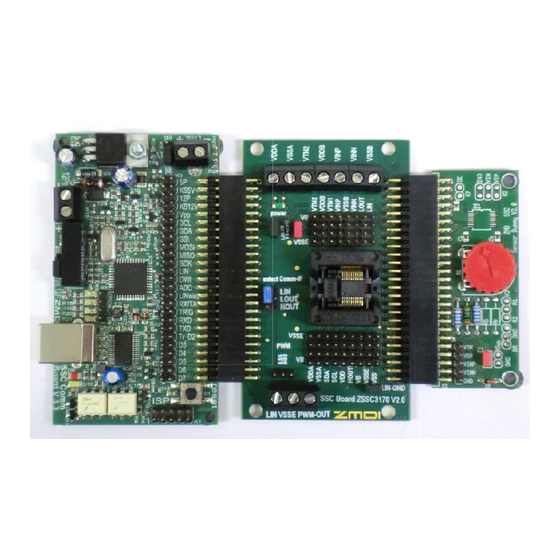
Page 5: Zssc3170 Evaluation Board
The main purpose of the SSC Evaluation Kit is to perform communication between the user’s PC and the ZSSC3170 (referred to as the DUT). The PC sends commands and data via the USB port on the CB (virtual COM †... -
Page 6: Schematic
There is a reverse polarity protection diode connected to a series resistor and then directly to the power supply of the ZSSC3170 (VB as shown in Figure 2.1). If the PWM interface is used, a 5V supply is required. Both power supplies are controlled by the microcontroller of the SSC CB. -
Page 7: Figure 2.2 Ssc Evaluation Board Schematic
ZSSC3170 Evaluation Kit Description Figure 2.2 SSC Evaluation Board Schematic KS12V LIN-VB KS12V SM4001 220N select 3.3K Comm - IF LIN_µC LOUT 100K /1OE LIN-IF /2OE HEF40098BTD KS12V KS5V KS12V KS5V KS5V VSupply KS12V 100N K4x9 K4x8 VDDA VTN2 VDDA... -
Page 8: Connections To The Zssc3170
Connections to the ZSSC3170 The SSC EB has an SSOP-20 socket for inserting the SSOP-20 ZSSC3170 under test. NOTE: Only one ZSSC3170 connection option can be used at a time (e.g., either through the SSC CB or via individual connections). -
Page 9: Pinout And Package
ZSSC3170 Evaluation Kit Description Pinout and Package Note: The ZSSC3170 is only available for purchase as die. The SSOP20 package is only available for evaluation purposes as samples in the Evaluation Kit. An SSOP20 Green Package (5.3mm body, 0.65mm lead pitch) is the standard delivery form for samples. -
Page 10: Zssc3170 Software
ZSSC3170 product page as follows: • Click on the link titled “ZSSC3170 Evaluation Software Rev. X” (where X is the current revision) and follow the dialog instructions as needed to download the zip file for the software. -
Page 11: User Files
After the ZSSC3170 Software is started, the main window is displayed (see Figure 4.1). The main window includes all the settings for configuration of the ZSSC3170 in a clear structure that hides the corresponding HEX commands behind buttons and pull-down menus. For a detailed description of the commands, refer to the ZSSC3170 Functional Description. -
Page 12: Interface Selection
Figure 4.1 Main Window of the Evaluation Software 4.4.1. Interface Selection The ZSSC3170 supports two interfaces for communication: Figure 4.2 Interface Selection Section LIN and I²C™ (see Figure 4.2). After starting the software, select the interface for the application in the “Interface Selection”... -
Page 13: Zssc3170 Configuration
EEP-->RAM : Copies the EEPROM contents into RAM using the C0 command. • Write&Cycle : Copies the current software settings into the RAM of the ZSSC3170 and starts the ‡‡ measurement cycle using the current RAM settings (command: 02 The “RAM/EEP updated” virtual LED (see Figure 4.4) displays the software configuration status compared with the attached ZSSC3170’s register content. -
Page 14: Analog Front End (Afe) Adjustment
(Figure 4.6). The ZSSC3170 can use two different temperature channels: one for the temperature that is used for the ZSSC3170’s internal calibration calculation and one that is used as an optional additional output signal during Normal Operating Mode (NOM). If only one temperature sensor is used and a temperature readout during NOM is required, then “CalibrTS CT”... -
Page 15: Application Settings
BBOOST : Enables the bias boost option for the AFE. 4.5. Operation Section The “Commands” and “Read Out Data” sections control the collection of data and configuration of the ZSSC3170. Figure 4.9 Normal Operation Section © 2016 Integrated Device Technology, Inc. -
Page 16: Normal Operation Mode (Nom)
Power IC OFF The Power OFF button in the “Commands” section (see Figure 4.9) can be used to power off the ZSSC3170. All communication interfaces are disabled, so no further communication is possible until the CMD ON button is sent or an interface is selected. -
Page 17: Enable Error Check
EMC. Typically, the slew rate is +/-2V per µs for the voltage range of 0.5V to 4V. §§ For details about ZSSC3170’s I²C™ interface, refer to the ZSSC3170 Functional Description. © 2016 Integrated Device Technology, Inc. March 30, 2016... -
Page 18: Lin Interface
LIN ConFiGuration STATus bits : In addition to sensor signal and temperature data included in the digital read out, the ZSSC3170 also provides various information with the remaining 4 status bits during NOM. There are different settings available, which can be selected by this pull-... -
Page 19: Calibration Window
“Calibration” on the top menu and then “Calibration” from the drop-down menu. It is used to perform a calibration of the ZSSC3170 with either the SRB or the user’s sensor module. Section 5 gives an example calibration using the commands on this screen. -
Page 20: Ram-Register Dialog Window
There is also a WriteEEP button to store all register contents into the EEPROM of the ZSSC3170. Register indexing corresponds to the ZSSC3170 memory addresses. The configuration of the ZSSC3170 is stored in 32 EEPROM 16-bit words. • Calibration coefficients for conditioning the bridge sensor signal... -
Page 21: Calibration-Register (Ram) Dialog
ZSSC3170 Evaluation Kit Description 4.9. Calibration-Register (RAM) Dialog The “Calibration-Register (RAM)” dialog is accessed by clicking the button at the top of the menu. This dialog provides the same functionality as the “RAM-Register” dialog window, except that the registers are separated by functionality groups. -
Page 22: 4.11. Send Command
If the “ask” check box is selected, a dialog asking for confirmation appears before each command is executed. Reads the output data buffer of the ZSSC3170. A loop delay can also be added between the readings. -
Page 23: Calibration Example
Connect the SSC CB, SSC EB, and SRB as shown in Figure 5.1. b) Press down on top of the socket on the SSC EB to open it and insert a ZSSC3170 (see Figure 5.1; note pin 1 orientation). -
Page 24: Software Startup
ZSSC3170 Evaluation Kit Description 5.2. Software Startup a) Start the ZSSC3170 Software by clicking on the desktop icon or activate the software from the Windows Start Menu folder: #Start_Menu#\ZMDI\ZSSC3170\ZSSC3170. b) Select “I2C – CB – USB” or “LIN – CB – USB” interface from the drop down menu in the “Interface Selection”... -
Page 25: Calibration Data Acquisition
Close the calibration window and trigger a measurement in the main window (see Figure 4.1) by clicking on either the Read or Read Loop button in the “Read Out Data” section. The ZSSC3170 is already running in Normal Operation Mode (NOM) because the cycle button was pressed in the calibration window. -
Page 26: Ordering Information
Item Product Sales Code Description ZSSC3170-KIT ZSSC3170 Evaluation Kit V1.0 (incl. Pos. 2, 3, 4, 5, 6) SSC Comm. Board V3.3 SSC Communication Board V3.3 (incl. USB cable) SSC Board ZSSC3170 V2.0 ZSSC3170 SSC Evaluation Board (SSC EB) V2.0 (includes 5 ZSSC3170 samples) SSC Sensor Replacement Board V2.0... -
Page 27: Related Documents
ZSSC3170 Functional Description SSC CB Application Note - USB Driver Installation SSC Communication Board Data Sheet SSC Sensor Replacement Board Data Sheet SSC Command Syntax ZSSC3170 Technical Note— Pad Coordinates, Die Dimensions, & Package Dimensions Visit www.IDT.com/ZSSC3170 www.IDT.com/ZSSC3170KIT or contact your nearest sales office for the latest version of these and other related documents. -
Page 28: Document Revision History
ZSSC3170 Evaluation Kit Description Document Revision History Revision Date Description 1.00 January 23, 2012 First release. 2.00 November 28, 2012 Edits related to update for software. Updates for contact information. 2.10 October 11, 2013 PWM operation and LIN Sleep mode incompatibility note added. - Page 29 Renesas' products are provided only subject to Renesas' Terms and Conditions of Sale or other applicable terms agreed to in writing. No use of any Renesas resources expands or otherwise alters any applicable warranties or warranty disclaimers for these products.
Need help?
Do you have a question about the ZSSC3170 and is the answer not in the manual?
Questions and answers