Table of Contents
Advertisement
Quick Links
ZMID4200
Description
The ZMID4200 Evaluation Kit enables evaluation of
the Renesas ZMID4200 Inductive Position Sensor IC
via Renesas' ZMID4200 Application Modules
(available separately).
The main purpose of the ZMID4200 Evaluation Kit is
communication between the user's computer and the
ZMID4200. The user's computer sends commands
and data via its USB port to the ZMID
Communication Board (ZMID-COMBOARD).
The microcontroller on the ZMID-COMBOARD
interprets these commands and relays them to the
ZMID4200 located on the ZMID4200 Application
Module using the one-wire interface (OWI)
communication interface.
The microcontroller also forwards data bytes from the
ZMID4200 back to the computer via the USB
connection. These bytes can be sensor readings,
ZMID4200 internal registers values, or ZMID4200
EEPROM contents.
The ZMID4200 EVKIT Application Software is a
graphical user interface (GUI) that is provided online
for the kit. It supports all ZMID4200 configurations
and enables the user to understand the functionality
of the ZMID4200 as well as perform measurements.
Figure 1. ZMID4200 Evaluation Kit and ZMID42200 Application Modules
Rev.1.0
Aug 9, 2021
Evalution Board Manual
Features
USB "plug and play" – no driver installation
■
needed
Small ZMID-COMBOARD: 4cm 7.3cm
■
■
One-wire communication interface (OWI) enables
quick and easy configuration and calibration of the
ZMID4200 using the user's computer
■
PWM, analog, or SENT output (programmable)
■
The modular design allows easy swapping in
different ZMID4200 Application Modules (available
separately) for evaluation using the same ZMID-
COMBOARD and ZMID4200 EVKIT Application
Software
The kit software is available for download from the
■
Renesas product page for the ZMID-COMBOARD:
http://www.renesas.com/ZMID4200stkit
■
Kit Contents
ZMID-COMBOARD
■
■
Micro-USB cable
Page 1
© 2021 Renesas Electronics
Advertisement
Table of Contents

Related Manuals for Renesas ZMID4200


Summary of Contents for Renesas ZMID4200
-
Page 1: Figure 1. Zmid4200 Evaluation Kit And Zmid42200 Application Modules
■ (available separately). ■ One-wire communication interface (OWI) enables The main purpose of the ZMID4200 Evaluation Kit is quick and easy configuration and calibration of the communication between the user’s computer and the ZMID4200 using the user’s computer ZMID4200. The user’s computer sends commands ■... - Page 2 ZMID4200 Evaluation Board Manual Important Notes Disclaimer Integrated Device Technology, Inc. and its affiliated companies (herein referred to as “Renesas”) shall not be liable for any damages arising out of defects resulting from delivered hardware or software (ii) non-observance of instructions contained in this manual and in any other documentation provided to user, or (iii) misuse, abuse, use under abnormal conditions, or alteration by anyone other than Renesas.
-
Page 3: Table Of Contents
Figures Figure 1. ZMID4200 Evaluation Kit and ZMID42200 Application Modules .............. 1 Figure 2. ZMID4200 Evaluation Kit Connections – ZMID4200 Arc Application Module Example ......6 Figure 3. ZMID-COMBOARD – Overview ........................ 6 Figure 4. ZMID4200 Rotary 360° Application Module – Overview ................7 Figure 5. - Page 4 ZMID4200 Evaluation Board Manual Figure 9. Display When Connected to a Device .....................11 Figure 10. Display When Connected to 2 Devices – ZMID4200 Example .............11 Figure 11. “OUTPUT” Tab – Analog Output Example ....................12 Figure 12. “INTERNAL VALUES” Tab – Analog Output Example................13 Figure 13.
-
Page 5: Setup
The ZMID4200 EVKIT Application Software is not included with the kit. To ensure use of the latest version of the software, it is available for download free of cost in zip file format from the Renesas web site on the web page given on page 1. -
Page 6: Overview Of The Hardware
ZMID4200 Evaluation Board Manual Overview of the Hardware Figure 2 shows the board connections for the ZMID4200 Evaluation Kit using the ZMID4200 Arc Application Module (ZMID4200MARC18001) as an example. Figure 2. ZMID4200 Evaluation Kit Connections – ZMID4200 Arc Application Module Example... -
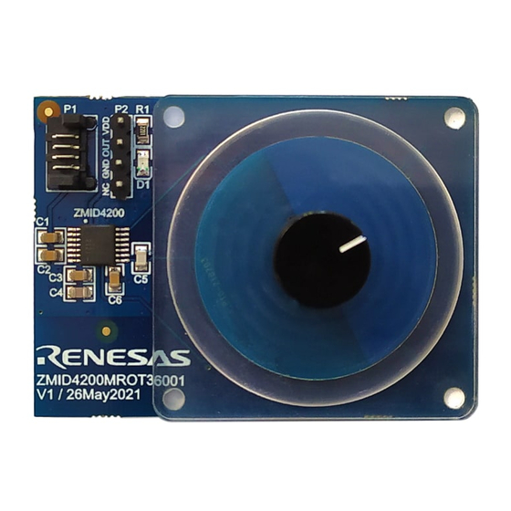
Page 7: Figure 4. Zmid4200 Rotary 360° Application Module - Overview
Application Module Sensor Board. If connecting to two modules at the same time, the ZMID4200 ICs on the modules must have the same output option (e.g., 2 xAnalog ouputs). Note that the same signals are available on the adjacent 4-pin header P3, which has labels for the pin signals: NC (no connection), GND, OUT, and VDD. -
Page 8: Connecting The Kit
5. The indicator LED2 on the ZMID-COMBOARD will light (see Figure 3) if conditions are normal. This indicates that the board is ready to communicate with the ZMID4200 EVKIT Application Software. The D1 LED on the ZMID4200 Application Module (see Figure 4, Figure 5, or Figure 6) also lights when the board is powered on. -
Page 9: Zmid4200 Evkit Application Software User Guide
2. ZMID4200 EVKIT Application Software User Guide Sections of the Display The ZMID4200 EVKIT Application Software provides a graphic user interface (GUI) for communicating with the kit. The GUI is displayed when the application is started. Figure 7 identifies the various sections of the display. -
Page 10: Getting Started
Data are displayed according to the selection made through the drop-down menu on the top left side (Module 1 or Module 2). When connecting to two modules at the same time, both ZMID4200 ICs on the modules must have the same output option (e.g., 2 x Analog outputs). -
Page 11: Reading Measurements
“INTERNAL VALUES” are displayed. For the ZMID4200, the “SENT” sub-tab is also displayed and provides a SENT interface decoder. The “OUTPUT” tab displays the reading at the ZMID4200 output pin SOUT. 2. The readings can be displayed as scaled values in percent or as raw (decimal/hexadecimal) values. Use the “Component 1”... -
Page 12: Figure 11. "Output" Tab - Analog Output Example
ZMID4200 Evaluation Board Manual are two devices, repeat the selection for the second device using the “Component 2” radio buttons. The “OUTPUT” tab readings in percent represent: ● Analog values– Percent of VDD ● PWM values– Duty cycle of the signal ●... -
Page 13: Figure 12. "Internal Values" Tab - Analog Output Example
The “SENT” tab is only available when the ZMID4200 Application Module is set to SENT output and connected to the ZMID-COMBOARD. It displays the decoded SENT data information as shown in Figure 13. -
Page 14: Changing The Configuration Settings
IC configuration. Each value represents a register or a part of a register from the internal memory of the device. The displayed memory type can be either the ZMID4200 EEPROM or the SWR memory. SWR refers to shadow registers used as the working memory for the ZMID4200, which can be temporarily written via the GUI to the ZMID4200 for development purposes. -
Page 15: Figure 15. Buttons In The "I/O Functions" Section
SWR settings to the EEPROM memory of the device. This section also provides the “Reset IC” button for manually resetting the ZMID4200. The reset power cycles the device and puts it in Command Mode. After reset, the contents of the EEPROM of the device are copied to its working memory SWR. -
Page 16: Calibration
The “COIL OFFSET” sub-tab is located under the “CALIBRATION” tab (see Figure 22). It is used to compensate the offset of the signal acquired from coils R1 and R2 connected to the ZMID4200. Figure 22. “COIL OFFSET” Tab – ZMID4200 Example For each of the coils, the following are displayed: 1. -
Page 17: Figure 23. Receiver Coil (Abs Value) Offset Example With Offset Compensation = /2
3. Values for the Offset will be updated (see Figure 24). 4. Use the “Write EEPROM” button from the “I/O FUNCTIONS” section to save the new values to the EEPROM. Figure 24. Coil Offset Calibration Completed – ZMID4200 Example Rev.1.0 Page 17... -
Page 18: Output Range" Sub-Tab
“OUTPUT RANGE” Sub-tab 2.4.2. The “OUTPUT RANGE” sub-tab (see Figure 25) is used to configure the output behavior of the ZMID4200. For a detailed description of output settings, refer to the ZMID4200 Datasheet. Figure 25. “OUTPUT RANGE” Tab – ZMID4200 Example There are four values that can be edited on the “OUTPUT RANGE”... -
Page 19: Figure 26. Linear Output Mode Example With Slope = 2, Offset = 90
Figure 27. Modulus Output Example with Slope = 2, Offset = 60° The results from the calibration procedure are displayed in two fields on the “OUTPUT RANGE” tab. They are direct representations of the Offset and Slope registers in the ZMID4200. The values can also be manually entered by the user. -
Page 20: Figure 28. Output Without Clamping
ZMID4200 Evaluation Board Manual Figure 28. Output without Clamping Figure 29. Output Clamped from 20% to 80% Automatic Output Calibration Procedure: To start the automatic calibration, click the “Start Calibration” button. The GUI will guide the user through a sequence of instructions for performing the calibration procedure. -
Page 21: Figure 30. Specify The Original Slope
ZMID4200 Evaluation Board Manual 3. Based on the acquired data, the GUI will attempt to calculate the best values for the Slope, Offset, and Clamps registers. If the calibration is not possible with the currently selected “Out MOD” setting, the GUI will ask the user to change to the other setting (see Figure 31). -
Page 22: Calibration And Linearization" Tab
The “AUTO CAL”” sub-tab is located under the “CALIBRATION AND LINEARIZATION” tab (see Figure 34). It is used to do a full calibration of the ZMID4200 by processing a .csv file with measurement data. Figure 34. "AUTO CAL" Sub-tab – ZMID4200 Example Rev.1.0... -
Page 23: Figure 35. Example Contents Of An Input .Csv File With Spatial Angle Data
If the “Use Analog values instead of Spatial Angle” checkbox is selected, the input .csv file must contain only ■ voltage readings from the output of the ZMID4200 taken at equal intervals during the whole movement range of the target. The values are written as positive real numbers in volts. -
Page 24: Figure 37. Example Of Auto Cal Error Messages
ZMID4200 Evaluation Board Manual The “VDD [V]” text box is used to specify the measured supply voltage of the ZMID4200 when the .csv data ■ was gathered. Note: This option is only available for the Analog output. The “Write Renesas Output Config” button writes a default configuration to the first 8 registers of the EEPROM ■... -
Page 25: Figure 38. "Manual Linearization" Sub-Tab - Zmid4200 Example
“Position 1” data fields. Three additional controls are available on this tab. Motion Range [mm] or [deg]: Entry field for the linear motion range in mm (not applicable to the ZMID4200 ■ Rotary 360 Application Module and the ZMID4200 Arc 130 Application Module) or the arc/rotation motion range in degrees. -
Page 26: Figure 39. Calibration Diagram
“MANUAL LINEARIZATION” Tab – Correction Values 2.4.3.3. Multiple strategies have been developed to obtain the set of correction values. For relevant information and procedures, contact Renesas support. (See the contact information on the last page.) Rev.1.0 Page 26 Aug 9, 2021... -
Page 27: Working With The Memory
(see Figure 40). The data is organized in tables, and the register values are in hexadecimal format. Figure 40. “MEMORY EDIT” Tab Contents – ZMID4200 Example The read-only registers are marked with a light blue background. Modified register values will appear in red color until they are written to the device memory or re-read from it (see Figure 41). -
Page 28: Saving And Loading Memory Dump Files
Since there is no device connected, only the “CONFIGURE” and “MEMORY EDIT” tabs are available (see Figure 44). The values that are different from the default values for the ZMID4200 are displayed in red. Connecting to a device while viewing a memory dump file “offline” will cause the GUI to discard any unsaved changes to the memory dump file and switch to displaying the current settings from the connected device’s memory. -
Page 29: Manually Identifying A Device
ZMID4200 Evaluation Board Manual Manually Identifying a Device When a new device is connected to the computer, the GUI automatically recognizes it. If it is unable to identify the device, the user must manually identify it. There is also a menu option to re-identify a device (see Figure 45). -
Page 30: Figure 46. File Dialog To Select An Identification File
ZMID4200 Evaluation Board Manual 3. In the resulting common file dialog, select the proper identification file based on the type of ZMID4200 Application Module, and click “Open.” The identification files can be found in the root directory in the Profiles folder (see Figure 46). -
Page 31: Firmware Update
9. Remove the jumper from the “BOOT” pins. To verify the firmware update, install a ZMID4200 Application Module and connect to the computer. The GUI will now display the new version of the firmware on the board information in the “ACTIVE DEVICES” section. -
Page 32: Zmid-Comboard Schematics
ZMID4200 Evaluation Board Manual 4. ZMID-COMBOARD Schematics Signals Multiplexing Circuit test1 ANALOG/DIGIT AL selection CH1 IO_0 3 CH1+ P ull-up control IO_03 AN16_CH1+ ANALOG IO_05 VDDE IO_0 4 CH2+ Inputs IO_04 AN16_CH2+ VDDE SIG1A SW control AN16_CH1+ IO_0 5 IO_05... -
Page 33: Zmid-Comboard Bom
ZMID4200 Evaluation Board Manual EMI Bead 3A 50mR 0805 Ferrie 3A ,50mR USB_micro_B_Attend VOUT = 3.31V USBPWR VPWR1 STPS1L40M AP2210K-ADJTRG1 100nF 6V3 X5R 20K, 0402, 1% 1.0A VBUS 22R, 0402, 1% MCU_USB_DM MCU_USB_DP 22R, 0402, 1% IC22 VFB = 2.0V... - Page 34 ZMID4200 Evaluation Board Manual Item Designator Value Description Footprint Qty. STPS1L40M DO216AA STMICROELECTRONICS - Schottky Rectifier, 40 V, 1 A, Single, DO-216AA, 2 Pins, 460 mV LPC1549 LQFP-100 NXP - ARM Microcontroller, LPC1500 ARM Cortex-M3 Microcontrollers, 32bit, 72 MHz, 256 KB, 36 KB, 100 Pins MCP6002-I/SN 2 OA,4.5mV,1pA,1.8-6V,100uA,1MHz...
-
Page 35: Sensors Boards
Single Edge Nibble Transmission Shadow Register – used as working memory for the ZMID4200 IC. Universal Serial Bus 8. Ordering Information Refer to the product pages for the specific ZMID4200 Application Module for the order codes for the module. Part Number Description ZMID-COMBOARD ZMID-COMBOARD, micro-USB cable 9. - Page 36 Koto-ku, Tokyo 135-0061, Japan www.renesas.com/contact/ www.renesas.com Trademarks Renesas and the Renesas logo are trademarks of Renesas Electronics Corporation. All trademarks and registered trademarks are the property of their respective owners.
Need help?
Do you have a question about the ZMID4200 and is the answer not in the manual?
Questions and answers