Advertisement
Quick Links
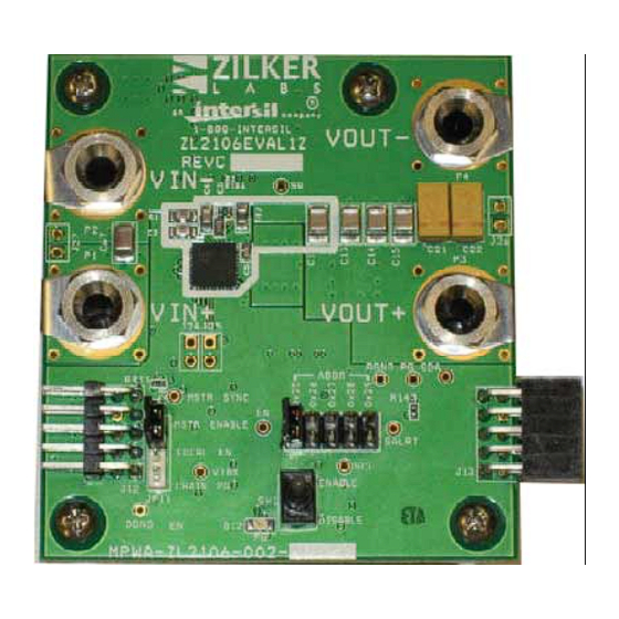
ZL2106EVAL1Z
Evaluation Board
Description
The ZL2106 is an innovative power conversion and
management IC that combines an integrated synchronous
step-down DC-DC converter with key power and fault
management functions in a small package, resulting in a
flexible and integrated solution. The ZL2106EVAL1Z platform
allows evaluation of the features in the highly configurable
ZL2106 in either stand-alone mode or via an I
interface.
A USB-to-SMBus reference board can be used to connect the
ZL2106EVAL1Z board to a PC. The PMBus command set is
accessed by using the PowerNavigator evaluation software
from a PC running Microsoft Windows.
Key Features
• Small, compact design
• PMBuscontrol
• Pin-strap selection for stand-alone operation
• V
settable from 0.6V to 5V
OUT
• Convenient power connection
• On-board enable switch
• Power-good indicator
POWER IN
SM BUS
TRACK INPUT
AN1468 Rev 2.00
Sep 15, 2011
2
C/SMBus™
SW1
EN
J12
SYNC
3
FIGURE 1. ZL2106EVAL1Z BLOCK DIAGRAM
USER'S MANUAL
Specifications
This board has been optimized as a buck regulator for the
following operating conditions:
• V
= 12V
IN
• V
= 3.3V
OUT
• I
= 6A (with airflow)
MAX
• f
= 400kHz
SW
• Peak Efficiency: >85% at 50% Load
• Output Ripple: <0.5% at 6A
• Dynamic Response: 3.5%
(3A to 5A and 5A to 3A Steps, di/dt = 2.5A/µs)
• Board Temperature: +25°C
Ordering Information
PART NUMBER
ZL2106EVAL1Z
ZL2106 Evaluation board only, one channel
ZL2106
VTRK
J13
AN1468
Rev 2.00
Sep 15, 2011
DESCRIPTION
POWER OUT
SYNC
SM BUS
PG
Page 1 of 19
Advertisement

Related Manuals for Renesas ZL2106EVAL1Z


Summary of Contents for Renesas ZL2106EVAL1Z
- Page 1 • Peak Efficiency: >85% at 50% Load A USB-to-SMBus reference board can be used to connect the • Output Ripple: <0.5% at 6A ZL2106EVAL1Z board to a PC. The PMBus command set is • Dynamic Response: 3.5% accessed by using the PowerNavigator evaluation software (3A to 5A and 5A to 3A Steps, di/dt = 2.5A/µs)
-
Page 2: Functional Description
All power to the board (V and I C/SMBus bus) must be the bottom side of the ZL2106EVAL1Z PCB. Once the desired removed before changing the jumpers. The back side of the pin-strap settings and component changes have been applied,... -
Page 3: Stand-Alone Operation
ZL2106EVAL1Z Quick Start Guide USB (PMBus) Operation 1. Follow Steps 1 - 4 for stand alone operation Stand Alone Operation 2. Insert the Zilker Labs Eval Kit CD 1. Set ENABLE switch to “DISABLE” 3. Connect USB-to-SMBus reference board to J12 of 2. - Page 4 ZL2106EVAL1Z SMBus Address Jumper Pin-Strap Settings Resistor FIGURE 2. ZL2106EVAL1Z EVALUATION BOARD (TOP SIDE AND BOTTOM SIDE) AN1468 Rev 2.00 Page 4 of 19 Sep 15, 2011...
- Page 5 R186 NI 6.3V 6.3V SGND SGND SGND VDDS 4.7uF 4.7uF VDDP DGND SYNC SYNC VSET VSET 47nF 47nF VOUT SALRT SALRT ZL2106 ZL2106 6.0uH 6.0uH PGND 10uF 10uF 100uF 100uF 6.3V 6.3V VTRK VSEN SGND SGND FIGURE 3. ZL2106EVAL1Z CIRCUIT...
- Page 6 SN74AUP1G17 SN74AUP1G17 R150 R150 SGND 4301 WESTBANK DRIVE 4301 WESTBANK DRIVE 4301 WESTBANK DRIVE BUILDING A, SUITE 100 BUILDING A, SUITE 100 BUILDING A, SUITE 100 AUSTIN, TEXAS 78746 AUSTIN, TEXAS 78746 AUSTIN, TEXAS 78746 SGND FIGURE 4. ZL2106EVAL1Z INTERFACE...
- Page 7 USB dongle. When no USB dongle is applied, dongle. When no USB dongle is applied, this regulator is supplying this regualtor is supplying Vi2c current thus efficiency Vi2c current, thus, efficiency measurements will be affected. measurements will be affected. VOUT FIGURE 5. ZL2106EVAL1Z POWER I/O...
- Page 8 ZL2106EVAL1Z TABLE 1. BILL OF MATERIALS REFERENCE MANUFACTURER PART NUMBER DESIGNATOR DESCRIPTION MANUFACTURER PART ZL2106EVAL1ZREVCPCB PWB-PCB, ZL2106EVAL1Z, REVC, ROHS IMAGINEERING INC ZL2106EVAL1ZREVCPCB H1045-00104-16V10-T C61, C64 CAP, SMD, 0603, 0.1µF, 16V, 10%, X7R, ROHS MURATA GRM39X7R104K016AD H1045-00105-25V10-T C3, C62 CAP, SMD, 0603, 1µF, 25V, 10%, X5R, ROHS...
- Page 9 ZL2106EVAL1Z (Continued) TABLE 1. BILL OF MATERIALS REFERENCE MANUFACTURER PART NUMBER DESIGNATOR DESCRIPTION MANUFACTURER PART CMD17-21VGC/TR8-T LED, SMD, 0805, GREEN, CLEAR, 10mcd, 2.1V, CHICAGO MINIATURE CMD17-21VGC/TR8 20mA, 570nm, ROHS BLM21AG102SN1D-T FERRITE CHIP, SMD, 0805, 1000Ω, 200mA, MURATA BLM21AG102SN1D 100MHz, ROHS MIC2920A-3.3WS...
- Page 10 ZL2106EVAL1Z (Continued) TABLE 1. BILL OF MATERIALS REFERENCE MANUFACTURER PART NUMBER DESIGNATOR DESCRIPTION MANUFACTURER PART 4-40X3/4-STANDOFF-SS Four corners STANDOFF, 4-40X3/4in, F/F, HEX, STAINLESS KEYSTONE 1921C STEEL, ROHS 5X8-STATIC-BAG Place assy in BAG, STATIC, 5X8, ZIPLOC, ROHS INTERSIL 212403-013 DOCUMENT #1...
- Page 11 ZL2106EVAL1Z ZL2106EVAL1Z Board Layout - 6 Layers FIGURE 6. TOP LAYER NOTE: TP2 is labeled SW but is connected to BST (see Figure 3 schematic). AN1468 Rev 2.00 Page 11 of 19 Sep 15, 2011...
- Page 12 ZL2106EVAL1Z ZL2106EVAL1Z Board Layout - 6 Layers (Continued) FIGURE 7. PCB – INNER LAYER 1 (VIEWED FROM TOP) AN1468 Rev 2.00 Page 12 of 19 Sep 15, 2011...
- Page 13 ZL2106EVAL1Z ZL2106EVAL1Z Board Layout - 6 Layers (Continued) FIGURE 8. PCB – INNER LAYER 2 (VIEWED FROM TOP) AN1468 Rev 2.00 Page 13 of 19 Sep 15, 2011...
- Page 14 ZL2106EVAL1Z ZL2106EVAL1Z Board Layout - 6 Layers (Continued) FIGURE 9. PCB – INNER LAYER 3 (VIEWED FROM TOP) AN1468 Rev 2.00 Page 14 of 19 Sep 15, 2011...
- Page 15 ZL2106EVAL1Z ZL2106EVAL1Z Board Layout - 6 Layers (Continued) FIGURE 10. PCB – INNER LAYER 4 (VIEWED FROM TOP) AN1468 Rev 2.00 Page 15 of 19 Sep 15, 2011...
- Page 16 ZL2106EVAL1Z ZL2106EVAL1Z Board Layout - 6 Layers (Continued) FIGURE 11. PCB – BOTTOM LAYER (VIEWED FROM TOP) AN1468 Rev 2.00 Page 16 of 19 Sep 15, 2011...
- Page 17 ZL2106EVAL1Z Typical Performance Curves for ZL2106 Buck Regulator Unless noted: V = 12V, V = 3.3V, f = 400kHz, T = +25°C 25.0 25.0 mV 25.0 mV 25.0 mV 12.5 12.5 mV 12.5 mV 12.5 mV 0 mV 0 mV 0 mV -12.5...
- Page 18 ZL2106EVAL1Z Default Configuration Text The following configuration text is loaded into the ZL2106EVAL1Z as default settings. Each PMBus command is loaded via the PowerNavigator software. The # symbol is used for a comment line. #Configuration file for ZL2106 OT_FAULT_RESPONSE 0xBF...
- Page 19 10. It is the responsibility of the buyer or distributor of Renesas Electronics products, or any other party who distributes, disposes of, or otherwise sells or transfers the product to a third party, to notify such third party in advance of the contents and conditions set forth in this document.
Need help?
Do you have a question about the ZL2106EVAL1Z and is the answer not in the manual?
Questions and answers