Table of Contents
Advertisement
l
n
g
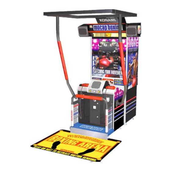
mocap boxi
l
Failure to operate the machine correctly could result in malfunction or accidents,eo
please
read this manual carefully before commencing operation. Be sum to operate the machine as
in this manual.
l
Keep this manual carefully so as to be ready for use when necessqry.
.
I
P.N. 400814
Advertisement
Table of Contents

Subscribe to Our Youtube Channel
Related Manuals for Konami Mocap Boxing


Summary of Contents for Konami Mocap Boxing
- Page 1 mocap boxi Failure to operate the machine correctly could result in malfunction or accidents,eo please read this manual carefully before commencing operation. Be sum to operate the machine as in this manual. Keep this manual carefully so as to be ready for use when necessqry. P.N.
- Page 2 About this product Thank you for purchasing this KONAMI product. This manual expl, .ins how to operate your game machine correctly and safely. operation. Be sure to operate the machine as describe in this manual. *This manual covers the following models: KONAMI MOCAP BOXING “Model # 100219”...
-
Page 3: Table Of Contents
Contents Precautions for use ..........1 Specifications ................ 8 2 Name of Parts ..............1 0 How to play ................1 1 5 Game settings ..............1 4 5-1 Checking the game performance........14 5-2 Setting and adjustment of game mode .... -
Page 4: Precautions For Use
Precautions for use people’s injuries and caused when the suggestions could result in dea to be followed. Indicates a matter which should *Definitions of qualified in-shop maintenance persons and industry specialist who handle this product. in-shop maintenance persons and industry specialists are defined as follows. Qualified in-shop maintenance... - Page 5 Precautions for use r than industry specialist Doing so could result in injury or product damage. or and make sure that the product is installed stably in a horizontal position. Unstable installation may result in injury or accident. outside. up this product outside could result in accidents or equipment so could block exits in time of emergency and could result in dea h or serious injury.
- Page 6 for use Precautions cord, use indoor wiring of the specified rating or more. to do so could result in fire or equipment failure. sure to use the attached power cord. a fire or machine trouble may result. *Never plug more than one cord at a time in the electrical receptacle. so could result in fire or electrical shock.
- Page 7 Precautions for use not use this product anywhere other than industrial areas. Use in a residential area or an area next to a residential area could affect signal reception of radios, television sets, telephones, etc.. *Players should be advised of the following precautions. so could cause accidents or illness.
- Page 8 Precautions for use receptacle before inspecting or cleaning the machine, to do so could result in electriial shock. *When replacing parts, be sure to use parts of the correct Never parts other than the specified ones. Using improper parts could result in fire or equipment failure. *There is high voltage inside the machine.
- Page 9 Precautions for use *The game machine contains parts such as the monitor, electronic co nponents and precision components which are sensitive to vibration and impact. Great care when therefore should be taken moving and transporting the game ma:hine. Be sure not to let the machine tlp over. *Before moving the machlne, be sure lo turn OFF the main power switl:h, unplug the power cord, and disconnect the power cord.
-
Page 10: Specifications
1 Specifications Dimensions Weight 1 Sensorframe.Approx.l6kg(353lb) 3 Support: Approx.4.5kg(9.9lb) Rated power (MAX) consumption Monitor CRT-Wells Gardner 2792 (MID-RES) Service condition Temperature 10 to 35-C (50 to 95’F), Humidity 20 to 80% (Nb dewing is allowed.) manual ,.,.., ,............Thi s manual -Product Registration Card . - Page 11 Allowance for Carrying-in and Installation of Produci The following allowance dimensions are necessary for Cal of the product. Provide a space of the following dimensions for installati clearances between and wallr products. would int the game.
- Page 12 2 Names of parts frame Fluorescent light...
-
Page 13: How To Play
game features a posture detecting ultrasonic sensor tha shifts the viewpoint on nt. Duck and dodge to avoid the punches of your opponent onscreen, and land your punche on him. While wearing the special gloves, you deliver hooks, uppercuts and jabs to the on creen boxer. You’re in the ring! Defeat the world’s strongest boxers to get to the top of the boxing world. - Page 14 4 Opening and closing the doow How to open the maintenance door - - - - - - - *Take care not to apply any load or impact to the mai securely. Insert the accompanying maintenance key and turn it clockwise.
- Page 15 4 Openi! g and closing the doors 4-2 Opening and closing the coin dodr Opening and closing the coin door and removing theicoin box - - - - - *Take care not to apply any load or impact to the coin c(oor when it is open. *Securely lock the door for protection againsttheft.
-
Page 16: Game Settings
5 Game settings not turned ON, either. setting. *If an abnormality persists or the machine does immediately turn OFF the main power switch, unplug 8 power cord from the receptacle and contact your nearest dealer. Result of test 11111-111m111111m If test is OK The machine goes to the game mode and the demonstrap/on game starts. -
Page 17: Setting And Adjustment Of Game Mode
5 Game settings 5-2 Setting and adjustment of game qode Manually check and change the settings for the screen displbys and game contents and change them as required. 1 Turn ON the power switch. 2 While the demonstration game is playing, press the te ‘ t button on the service panel. -
Page 18: Mode Descriptions
5 Game settings 5-3 Mode descriptions original factory settings are displayed in green; the changed settings are displayed in red. button to change the setting. button for entry. “NOW SAVING” will appear, the modified settings will be aved, and the screen returns to the main menu. - Page 19 5 Game settings Mode for checking the performance of the controls. To return to the main menu screen, press the start buttorb while pressing the left select button. . Displaying he sl Of switches is on. is off. FC (hexadecfm~ the red frame 4 If ths *error is ii button is held PI...
- Page 20 Game settings ing the glove sensor Mode for checking the glove sensor. Stretch the glove to rd the screen to check the glove sensor performance. To return to the main menu screen, press the start button *Anytime the glove unit has been repaired or replace the glove reactron.
- Page 21 5 Game settings n Mode for checking the screen display. Adjust the focus, distortion and size of the image on the s ‘reen while watching the crosshatch pattern. Use the monitor adjustment PCB (See pag 37) to make adjustments. To return to the main menu screen, press the start button. 1 ( n Mode for checking the display color.
- Page 22 5 Game settings the C.G. performance Checking Mode for checking the function of the C.G.. Watch the screen in this mode to make sure the images al To return to the main menu screen, press the start button. arious sound options Sefflng 1 ress the start button to Press the right or left select button to select an item, and...
- Page 23 5 Game settings options Mode for setting and checking the game options. Press the right or left select button to select an item, and1 press the start button to change the setting. To return to the main menu screen, select “SAVE AND ENIT’ or “EXIT’ and press the start button.
- Page 24 Press the right or left select button to select an item, and press stat-l button to change the setting. To return to the main menu screen, select “SAVE AND EXIT’ or “EXIT and press the start button. In such case, remember the games will be free. Sets the number Sets the number...
- Page 25 5 Game settings Displaying the bookkeeping information of coins Mode for displaying the total data on the number of coins put in the machine. If the time is preset on the “CLOCK SETUP” screen, the total data on the number of coins put into the machine can be checked for each coin slot.
- Page 26 5 Game settings Screen of the total number of coins for last 7 days Screen of the total number of coins for each day of the week Screen of indication of play conditions...
- Page 27 5 Game settings Screen of the total number of coins per hour. Mode of returning all the settings of each mode to their factory settings. Press the right or left select button to select “YES” or “NO”.. Press the start button to enter the decision.
-
Page 28: Installation And Assembly
6 Installation and assembling 6-1 Fastening the adjusters How to fasten the cabinet adjusters 111mmmm1111111111 Take care not to exceed the maximum adjusting height of the adjuster. *Make all the cabinet adjusters come in contact with the floor, tighten them with hexagon nuts after making sure that the cabinet is placed in a horizontal and stable position. -
Page 29: Spreading The Foot Sheet
6 installation and assembling 6-2 Spreading the foot sheet *When spreading the foot sheet, flx the cabinet unit adjusters. *Do not apply any oil or sticky substance, such as wax, to the top surface Stick the attached double-face tape to the backside of the foot sheet and place that on the floor. -
Page 30: Attaching The Foot Protective Guard
6 Installation and assembling 6-3 Attaching the foot protective guard Make sure the machine is secured on the adjusters. Then place and fix the guard in the specified position, prevent players from getting their feet between the floor and the machine bottom and from getting injured. -
Page 31: Mounting The Sensor Frame
6 Installation and assembling 6-4 Mounting the sensor frame How to mount the sensor frame 111111mmm1111m1111 26.6 lb. Be sure to have a team of 2 or more people in detaching and attaching it and to use a stepladder for added safety. and wails as well as other products. - Page 32 6 Installation and assembling Attach sensor frame (as shown in the picture to the right), to the top of the vertical support bars. Fasten the bolts provided on each side of the sensor frame where it meets the vertical support bars simultaneously.
- Page 33 6 Installation and assembling Next attach extension support bar, shown at the right, in front of the cabinet. Using the bolts provided, attach the extension support bar to the front of the cabinet. Once mounted it should appear as shown in the picture to the right, but withpipes mounted to front face, not sides, of the cabinet.
-
Page 34: Maintenance
7 Maintenance 7-1 Replacing the coin selector *Before replacing the coin selector, be sure to turn OFF the main power *Take care not to apply any load or impact to the maintenance door when It is open. *After closing the maintenance door, be sure to check that the door is locked securely. *When replacing parts, be sure to use parts of the correct speciflcatlons. -
Page 35: Replacing The Glove Unit
Maintenance 7-2 Replacing the glove unit Check the gloves daily and replace them as required. Howtoreplacethegloveunit *Before replacing the glove unit, be sure to turn OFF the main power switch and unplug the power cord from the receptacle. *After the glove unit has been repaired or replaced, check the glove reaction. (“GLOVE CHECK”... - Page 36 Maintenance Loosen the clamp at the back of the cable bracket, and draw out the cable. Back of the cable bracket Remove the screws and detach the glove cover. Detach the flange nuts fixing the cable ass’y and take out it. the glove unit and the cable ass’y disconnected.
- Page 37 Maintenance in setting up the cable assemblies The cable assemblies come for the right and left sides. Be careful not to confuse the right and left units when connecting them to the glove units. Left Riaht...
-
Page 38: Resetting The Circuit Protector
7 Maintenance 7-3 Resetting the circuit protector If an overcurrent or short circuit occurs, the circuit protector will be automatically actuated to protect the electric circuits of the game machine. When resetting the circuit protector, turn OFF the main power switch, unplug the power cord from the receptacle, eliminate the cause, and then press the button of the circuit protector. -
Page 39: Adjusting The Monitor
Maintenance 7-4 Adjusting the monitor The monitor has already been adjusted at the time of shipment, but it may be readjusted as desired. refer to “~CJ?~~N CHECK” and “COLOR CHECK” on . . , , -. . - -, - - . J . - - specialist should open the back door. -
Page 40: Troubleshooting
7 Maintenance If the power switch is turned ON but the machine fails to start properly, take the following measures. If the machine still malfunctions or any other problem than described below occurs, immediately turn OFF the main power switch, unplug the power cord from the Trouble Measures No image on screen,... - Page 41 7 Maintenance Trouble Possible causes and check points Measures Coin selector malfunctioning. Coin selector detective. Check the performance on the ‘I/O CHECK” screen. coin selector or microswitch with new one. Make proper setting on the No sound or too loud (or too soft) Sound level maladjusted.
- Page 42 7 Maintenance Trouble (Possible causes and check Points ( Measures the initial Some connectors disconnected device check, but this check or wires broken. switch, unplug the power cord is repeated without going to from the receptacle and check all the connectors for poor the game mode.
- Page 43 MEMO...
- Page 44 8 Annex No. ( N A M E NOTE S I D E LABEL, DECAL...
- Page 45 8 Annex...
- Page 46 8 Annex FIG.2 UNIT, SENSOR FRAME 111111-1-111-1111111...
- Page 47 8 Annex...
-
Page 48: Annex
Annex... -
Page 49: Wiring Diagrams
8-2 Wiring Diagrams...
Need help?
Do you have a question about the Mocap Boxing and is the answer not in the manual?
Questions and answers