Table of Contents
Advertisement
Advertisement
Table of Contents

Related Manuals for Konami Dance Dance Revolution


Summary of Contents for Konami Dance Dance Revolution
- Page 1 PN.0000068482 GN845...
- Page 2 About this product Thank you for purchasing this KONAMI product. This manual explains how to operate your game machine correctly and safely. •Failure to operate the machine correctly could result in malfunction or accidents, so please read this manual carefully before commencing operation.
-
Page 3: Table Of Contents
Contents Precautions for use .................. 2 Locations of warning and other safety labels ........7 Specifications ................... 8 Names of parts ..................10 How to play ..................... 11 Opening and closing the doors 4-1 Opening and closing the maintenance door ......... 12 4-2 Opening and closing the coin door ............ -
Page 4: Precautions For Use
Precautions for use The following safety precautions are given throughout this manual. They must be strictly followed to protect those who install, use or maintain this product as well as to prevent other people’s injuries and property damages. Be sure to read the following •The following suggestions show the degree of danger and damage caused when the product is used improperly with the suggestions disregarded. - Page 5 Precautions for use Setting Up WARNING •Be sure to consult your nearest dealer when setting up, moving or transporting this product. ·This product should not be set up, moved or transported by anyone other than industry specialist. Doing so could result in injury or product damage. ·When installing this product, set the 12 adjusters stable on the floor and make sure that the product is installed stably in a horizontal position.
- Page 6 Precautions for use Setting Up CAUTION •Be sure to use indoor wiring for within the specified voltage range. For extension cord, use indoor wiring of the specified rating or more. ·Failure to do so could result in fire or equipment failure. •Be sure to use the attached power cord.
- Page 7 In case of any trouble, ask your nearest dealer for repairs and other services. Konami will not resume any responsibility for the damage to the product attributable to disassembly and repair of parts which are not indicated in this manual, as well as settings and remodelling.
- Page 8 Precautions for use Inspection and cleaning CAUTION •The spotlight halogen lamp is still very hot immediately after the power switch is turned OFF. Replace the lamp after confirming that it is sufficiently cooled. ·Otherwise, a burn or unexpected injury may result. •The stage units is so constructed that foreign matters such as sand etc.
-
Page 9: Locations Of Warning And Other Safety Labels
Locations of warning and other safety labels Types of warning and other safety labels... -
Page 10: Specifications
1 Specifications 1210(47.6) (5.9) 1080(42.5) (8.0) 730(28.7) 890(35.0) 890(35.0) 2160 to 2360(85.0 to 92.9) 1780(70.1) Adjustable range: 200mm(8.0) Specifications Dimensions Refer to the figure above : mm (in) Total weight: Approx.437 kg(964 lb) 1 Cabinet unit: Approx.207 kg(456 lb) Weight 2 Stage unit (L): Approx.100 kg(220.5 lb) 3 Stage unit (R): Approx.100 kg(220.5 lb) 4 Title unit: Approx.28 kg(61.7 lb) 5 Unit connection pipe: Approx.2 kg(4.4 lb) - Page 11 Allowance for Carrying-in and Installation of Product The following allowance dimensions are necessary for carrying the product indoors. 900 mm (35.4 in) or more •Do not hold the unit connection pipe when moving this product. •Do not apply a strong force for moving the units.coins.
-
Page 12: Names Of Parts
2 Names of parts... -
Page 13: How To Play
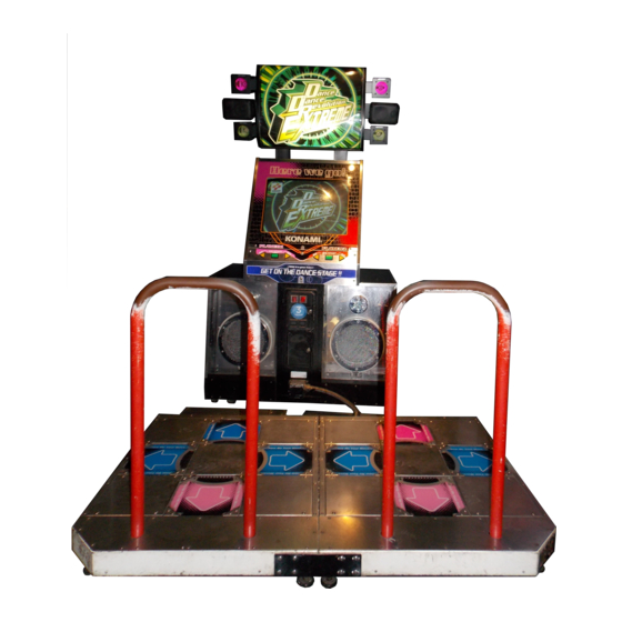
3 How to play “Dance Dance Revolution ” is such a game that one or two players step on any of the foot panels corresponding to the four kinds of arrows, which appear from the lower part of the screen, timely in accordance with music. -
Page 14: Opening And Closing The Doors
4 Opening and closing the doors 4-1 Opening and closing the maintenance door How to open the maintenance door •Take care not to apply any load or impact to the maintenance door when it is open. •After closing the maintenance door, be sure to check that the door is locked securely. -
Page 15: Opening And Closing The Coin Door
4 Opening and closing the doors 4-2 Opening and closing the coin door Opening and closing the coin door and removing the coin box •Take care not to apply any load or impact to the coin door when it is open. •Securely lock the door for protection against burglaries. -
Page 16: Game Settings
5 Game settings 5-1 Checking the game performance When the power switch is turned ON after installation of machine, the performance of game Printed Circuit Boards (PCB) is checked automatically and the result is displayed on the screen. If the power is not turned ON, make sure that the main power switch and sub-power switch are both at the ON position. -
Page 17: Setting And Adjustment Of Game Mode
5 Game settings 5-2 Setting and adjustment of game mode Manually check and change the settings for the screen displays and game contents and change them as reguired. Starting the test mode 1 Turn ON the power switch. 2 While the demonstration game is playing, press the test button on the service panel. -
Page 18: Mode Descriptions
5 Game settings 5-3 Mode descriptions The original factory settings are displayed in green; the changed settings are displayed in red. ·Press the 1P select button to select a mode to be modified. Press the 2P start button to change the setting. ·After the setting has been changed, select “SAVE AND NEXT”... - Page 19 To return to the main menu screen, press the 1P start button. (The game can be interrupted at any time during a play.) •If “BAD” is indicated, immediately turn OFF the power switch, unplug the power cable and contact your nearby “Konami Service Center”. DIP SWITCH CHECK Indicationing the DIP switch settings Mode for checking the setting of the DIP switches.
- Page 20 5 Game settings CG CHECK Checking the CG board performance Mode for checking the CG board function. Check the function of the CG board by watching the motion on the screen in this mode to see if the board works normally or not. To return to the main menu screen, press the 1P start button.
- Page 21 5 Game settings GAME OPTIONS Setting various game options Mode for setting and checking the game options. Press the 1P select button to select an item. Press either the 2P start button or select button to change the setting. To return to the main menu screen, select “SAVE AND EXIT” or “EXIT” and press the 1P start button.
- Page 22 5 Game settings BOOKKEEPING Displaying the bookkeeping information of coins Mode for displaying the total data on the number of coins put in the machine. If the time is preset on the “CLOCK SETUP” screen, the total data on the number of coins put into the machine can be checked for each coin slot.
- Page 23 5 Game settings Screen of the total number for last 7 days VIEW BOOKKEEPING INFORMATION TOTAL COINS Total number of coins after the time being set. COIN DATA OF LAST 7 DAYS Number of coins of yesterday. YESTERDAY -2DAY Number of coins of 2 days ago. -3DAY Number of coins of 3 days ago.
- Page 24 5 Game settings Screen of the total number of coins per hour. VIEW BOOKKEEPING INFORMATION COIN DATA BY THE HOUR 00 : 00 0 08 : 00 0 16 : 00 0 Total number of coins per hour. 01 : 00 0 09 : 00 0 17 : 00 0 02 : 00 0...
-
Page 25: Installation And Assembling
6 Installation and assembling 6-1 Connection of units How to connect the stage units •Do not apply a strong force for moving the stage units after connection. •Never move the stage units across a step after connection. •Pay full attention not to pinch wires in the connection of the stage units. Remove plates shown in the figure from the stage units. - Page 26 6 Installation and Assembling How to connect the stage units and cabinet units •Do not hold the unit connection pipe for moving the units. •Do not apply a strong force for moving the units after connection. •Do not move the units across a step after connection. •Pay full attention not to pinch the wires when connecting the units.
- Page 27 6 Installation and Assembling How to mount the title unit •Before mounting the title unit, be sure to fix the units by adjusters. (See the description of 6-2. Fastening the adjusters on page 34.) •The title unit weighs 28 kg approx. Be sure to carry out the mounting work by three persons or more, using a stepladder for safety sake.
-
Page 28: Fastening The Adjusters
6 Installation and Assembling How to mount the stage plates •Be sure to mount the stage plates which effectively prevent the stage unit from lifting. •Mount the stage plate after the fixation of adjusters of each unit. Mount the stage plates, which Stage plates have been removed in step 2 on page 31, with the accompanying... -
Page 29: Power Unit
6 Installation and Assembling 6-3 Power unit Power unit The power supply unit is provided at the rear side of the cabinet unit. •Be sure to use the attached AC power cord. •Be sure to ground to the machine. Never connect the grounding wire to gas pipe, water pipe or telephone ground terminal. -
Page 30: External Output Terminals
6 Installation and Assembling 6-5 External output terminals External output terminals For video output and audio output from this product, the external output terminals are provided at the rear side of cabinet. External output terminals The RGB output terminal adopted in this product is of 3.3Vp-p. -
Page 31: Mounting Billboards
6 Installation and Assembling 6-6 Mounting billboards Mounting billboards 1 Fold along all lines. Fold the flaps upright and fix it on the inside of flap. Fold Fold Back Fold Fold Put the flap ends together and fix them with an adhesive tape(not included). 2 Remove three protection seals and attach the billboard to the cabinet. -
Page 32: Splitting Into And Moving Of Units
6 Installation and Assembling 6-7 Splitting into and moving of units How to split into units This product can be split into individual units. •Before splitting the product, be sure to turn OFF the main power switch and unplug the power code from the receptacle. •When moving this product, be sure to split it into the stage units, cabinet unit and unit connection pipe and remove connectors. -
Page 33: Moving The Coin Counter
6 Installation and Assembling 6-8 Moving the coin counter How to move the coin counter The coin counter was installed in the coin box when the machine left the factory, but it can be moved onto the service panel. •Before moving the coin counter, be sure to turn OFF the main power switch and unplug the power cord from the receptacle. -
Page 34: Maintenance
7 Maintenance 7-1 Replacing the coin selector How to replace the coin selector •Before replacing the coin selector, be sure to turn OFF the main power switch and unplug the power cord from the receptacle. •When replacing parts, be sure to use parts of the correct specifications. Never use parts other than the specified ones. -
Page 35: Replacing The Fluorescent Light
7 Maintenance 7-2 Replacing the fluorescent light How to replace the fluorescent light •Before replacing the fluorescent light, be sure to turn OFF the main power switch and unplug the power cord from the receptacle. •Open and close the fluorescent light cover gently. •The florescent light is hot just after the power switch is turned off. -
Page 36: Replacing The Spotlight Lamp
7 Maintenance 7-3 Replacing the spotlight lamp How to replace the spoilight lamp •Before replacing the halogen lamp, be sure to turn OFF the main power switch and unplug the the power cord from the receptacle . •The halogen lamp is still very hot immediately after the power switch is turned off. -
Page 37: Replacing The Button
7 Maintenance 7-4 Replacing the button How to replace the button •Before replacing the button, be sure to turn OFF the main power switch and unplug the power cord from the receptacle. •When replacing parts, be sure to use parts of the correct specifications. Never use parts other than the specified ones. - Page 38 7 Maintenance Start button Select button Loosen the nuts and separate the button. Guide Guide Button Button To fit the button again Set the buttons so that the projections at the back side of buttons should fit into the holes of panel and fix them by nuts. Pay attention to the posture of buttons, and sockets and assemble them in the reverse of disassembly, using care not to confuse the wires.
-
Page 39: Maintenance Of Foot Switch
7 Maintenance 7-5 Maintenance of foot switch Maintenance of foot switch •Before replacing the foot switch, be sure to turn OFF the main power switch and unplug the power cord from the receptacle. •The stage units is so constructed that foreign matters such as sand etc. easily enter the clearance between the foot panel and the corner metals or the inside of the foot panel. - Page 40 7 Maintenance Cut off the band which is binding wires and pull out one foot switch Foot switch connector. Remove the bracket which holds the foot switch. The band which is •Do not mount the thrust washers in binding wires wrong direction.
-
Page 41: Resetting The Circuit Protector
7 Maintenance 7-6 Resetting the circuit protector How to reset the circuit protector If an overcurrent or short circuit occurs, the circuit protector will be automatically actuated to protect the electric circuits of the game machine. When resetting the circuit protector, turn OFF the main power switch, unplug the power cord from the receptacle, eliminate the cause, and then press the button of the circuit protector. -
Page 42: Adjusting The Monitor
7 Maintenance 7-7 Adjusting the monitor Monitor adjustment PCB The monitor has already been adjusted at the time of shipment, but it may be readjusted as desired. The monitor adjustment PCB is located inside the service panel. When adjusting the monitor, open the maintenance door. (See page 20) Contrast adjustment CONTRAST Used to changes the contrast. -
Page 43: Annex
8 Annex 8-1 Label locations and exploded view Label... - Page 44 8 Annex FIG.1 UNIT, CABINET(1/4)
- Page 45 8 Annex FIG.2 UNIT, CABINET(2/4)
- Page 46 8 Annex FIG.3 UNIT, CABINET(3/4)
- Page 47 8 Annex FIG.4 UNIT, CABINET(4/4)
- Page 48 8 Annex FIG.5 UNIT, TUBE/ASS'Y DOOR COIN...
- Page 49 8 Annex FIG.6 ASS'Y, SERVICE...
- Page 50 8 Annex FIG.7 ASS'Y, BOX SPEAKER...
- Page 51 8 Annex FIG.8 ASS'Y, START...
- Page 52 8 Annex FIG.9 UNIT, TITLE...
- Page 53 8 Annex FIG.10 ASS'Y, LIGHT A/B...
- Page 54 8 Annex FIG.11 ASS'Y, SPEAKER/ASS'Y LAMP...
- Page 55 8 Annex FIG.12 UNIT, STAGE L(1/2)
- Page 56 8 Annex FIG.13 UNIT, STAGE L(2/2)
- Page 57 8 Annex FIG.14 UNIT, STAGE R(1/2)
- Page 58 8 Annex FIG.15 UNIT, STAGE R(2/2)
- Page 59 8 Annex FIG.16 UNIT, STAGE L/R...
- Page 60 8 Annex FIG.17 ASS'Y POWER BOX...
- Page 61 8 Annex FIG.18 UNIT, BOX AMP...
- Page 62 8 Annex FIG.19 ASS'Y, TRANSFORMER...
- Page 63 8 Annex FIG.20 UNIT, ATTACHMENT...
- Page 64 MEMO...
-
Page 65: Wiring Diagram
8 Annex GN845-UC specifications for regions using 120 voltage area in the U.S.A.. 8-2 Wiring diagram... - Page 66 8 Annex GN845-UC specifications for regions using 120 voltage area in the U.S.A.. 2/2 Wiring diagram...
Need help?
Do you have a question about the Dance Dance Revolution and is the answer not in the manual?
Questions and answers