Table of Contents
Advertisement
Advertisement
Table of Contents

Related Manuals for Konami Silent Scope


Summary of Contents for Konami Silent Scope
- Page 1 ● Failure to operate the machine correctly could result in malfunction or accidents,so please read this manual carefully before commencing operation. Be sure to operate the machine as described in this manual. ● Keep this manual carefully so as to be ready for use when necessary.
- Page 2 About this product Thank you for purchasing this KONAMI product. This manual explains how to operate your game machine correctly and safely. •Failure to operate the machine correctly could result in malfunction or accidents, so please read this manual carefully before commencing operation.
-
Page 3: Table Of Contents
Contents Precautions for use .................. 2 ........................10 Locations of warning and other safety labels ........7 ................15 Specifications ................... 8 ........................16 Names of parts ..................18 How to play ..................... 19 Opening and closing the doors 4-1 Opening and closing the maintenance door ......... 20 4-2 Opening and closing the coin door ............ -
Page 4: Precautions For Use
Precautions for use The following safety precautions are given throughout this manual. They must be strictly followed to protect those who install, use or maintain this product as well as to prevent other people’s injuries and property damages. Be sure to read the following •The following suggestions show the degree of danger and damage caused when the product is used improperly with the suggestions disregarded. - Page 5 Precautions for use Setting Up WARNING •Be sure to consult your nearest dealer when setting up, moving or transporting this product. ·This product should not be set up, moved or transported by anyone other than industry specialist. Doing so could result in injury or product damage. ·When installing this product, set the 6 adjusters stable on the floor and make sure that the product is installed stably in a horizontal position.
- Page 6 Precautions for use Setting Up CAUTION •Be sure to use indoor wiring for within the specified voltage range. For extension cord, use indoor wiring of the specified rating or more. ·Failure to do so could result in fire or equipment failure. •Be sure to use the attached power cord.
- Page 7 In case of any trouble, ask your nearest dealer for repairs and other services. KONAMI will not resume any responsibility for the damage to the product attributable to disassembly and repair of parts which are not indicated in this manual, as well as settings and remodelling.
- Page 8 Precautions for use Moving and transportation CAUTION •The game machine contains parts such as the monitor, electronic components and precision components which are sensitive to vibrations and impacts. Great care therefore should be taken when moving and transporting the game machine. Be sure not to let the machine tip over.
-
Page 9: Locations Of Warning And Other Safety Labels
Locations of warning and other safety labels Types of warning and other safety labels • The above is an example. The entries are different from destination to destination. -
Page 10: Specifications
1 Specifications 1653 (65.1) 816 (32.1) Specifications Dimensions Refer to the figure above : mm (in) Approx.249 kg (549 lb) Weight 1 Monitor unit: Approx. 127 kg (280.0 lb) 3 Title unit : Approx. 12 kg (26.5 lb) 2 Control unit : Approx. 110 kg (242.5lb) •GQ830-TB : 215W (MAX) Rated power consumption •GQ830-HD: 170W (235VA) - Page 11 1 Specifications Allowance for Carrying-in and Installation of Product The following allowance dimensions are necessary for carrying the product indoors. 816 mm(32.1 in) or more •Do not apply a strong force for Rifle unit moving the machine. •Do not hold the rifle unit when moving the machine.
- Page 18 816 (32.1) 1653 (65.1) 249kg (549lb) 127kg (280.0lb) 12kg (26.5lb) 110kg (242.5lb) GQ830-TB : 215W (MAX) GQ830-HD : 170W (235VA) (50 ~ 95˚F) 20 70...
- Page 19 816 mm(32.1 in) 100 mm(3.94 in)
-
Page 20: Names Of Parts
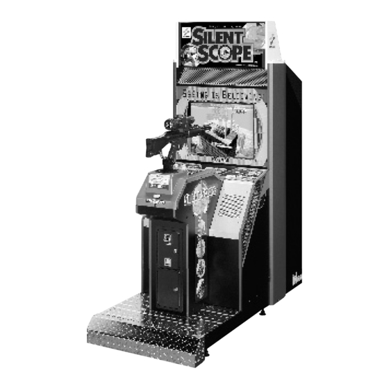
2 Names of parts Fluorescent light Title unit Monitor unit Monitor glass Scope Demagnetizing button (Main monitor) Main Rifle unit monitor Monitor adjustment door Speaker Start button Control unit Monitor adjustment PCB Coin input port Speaker Coin return lever Coin return port Maintenace door Coin door unit Test button... -
Page 21: How To Play
3 How to play The “SILENT SCOPE ” gun shooting game is for you to look into the rifle unit’s scope and snipe at enemy characters. Looking through the scope, you can find images in the distance or in the dark which cannot be pinpointed on the main monitor screen. You are challenged to find out a target quickly and shoot at it precisely at the first fire. -
Page 22: Opening And Closing The Doors
4 Opening and closing the doors 4-1 Opening and closing the maintenance door How to open the maintenance door •Take care not to apply any load or impact to the maintenance door when it is open. •After closing the maintenance door, be sure to check that the door is locked securely. -
Page 23: Opening And Closing The Coin Door
4 Opening and closing the doors 4-2 Opening and closing the coin door Opening and closing the coin door and removing the coin box •Take care not to apply any load or impact to the coin door when it is open. •Securely lock the door for protection against burglaries. -
Page 24: Opening And Closing The Monitor Adjustment Door
4 Opening and closing the doors 4-3 Opening and closing the monitor adjustment door How to open the monitor adjustment door •When opening the monitor adjustment door, be careful not to hit it against the monitor glass. •When closing the monitor adjustment door, be very careful not to get your finger pinched by the door. -
Page 25: Game Settings
5 Game settings 5-1 Checking the game performance When the main power switch is turned ON after installation of machine, the game Printed Circuit Boards (PCB) is checked automatically and the result is displayed on the screen. •Be sure to check the PCB unit (self test) before using the machine. •Once the main power switch has been turned on (while the PCB unit is being checked), never touch the rifle unit until the demonstration game gets started. -
Page 26: Setting And Adjustment Of Game Mode
5 Game settings 5-2 Setting and adjustment of game mode Manually check and change the settings for the screen displays and game contents and change them as reguired. Starting the test mode 1 Turn ON the main power switch. 2 While the demonstration game is playing, press the test button on the service panel. -
Page 27: Mode Descriptions
5 Game settings 5-3 Mode descriptions The original factory settings are displayed in green; the changed settings are displayed in red. ·Pull the rifle unit’s trigger to select a setting to be modified, and press the start button to change the setting. ·After the setting has been changed, select “SAVE AND NEXT”... - Page 28 5 Game settings GUN CHECK Checking the performance of the rifle unit Mode for adjusting and checking the rifle unit’s swing range. Look at the screen for the marker that the gun barrel is pointing to. If the marker is extremely out of position, press the test button on the service panel to call the gun adjustment mode.
- Page 29 5 Game settings SCOPE SCREEN ADJUST Adjusting the scope screen position Mode for adjusting the display position on the scope screen. Pull the rifle unit’s trigger to select an item. Press the start button to modify the setting. Looking into the scope, adjust so that the crosshatch pattern be centered. To return to the main menu screen, select “SAVE AND EXIT”...
- Page 30 To return to the main menu screen, press the start button. C. G. BOARD CHECK The product’s logo mark flashes semi-transparent here. (The KONAMI logo mark appears on the scope.) Two cubes are turning entangled each other behind the logo mark.
- Page 31 5 Game settings GAME OPTIONS Setting various game options Mode for setting and checking the game options. Pull the rifle unit’s trigger to select an item. Press the start button to modify the setting. To return to the main menu screen, select “SAVE AND EXIT” or “EXIT” and press the start button.
- Page 32 5 Game settings COIN OPTIONS Setting various coin options Mode for setting and checking the coin options. Pull the rifle unit’s trigger to select an item. Press the start button to modify the setting. To return to the main menu screen, select “SAVE AND EXIT” or “EXIT” and press the start button.
- Page 33 5 Game settings BOOKKEEPING Displaying the bookkeeping information of coins Mode for displaying the total data on the number of coins put in the machine. If the time is preset on the “CLOCK SETUP” screen, the total data on the number of coins put into the machine can be checked for each coin slot.
- Page 34 5 Game settings Screen of the total number of coins for last 7 days BOOKKEEPING INCOME DATA of LAST 7DAYS SLOT1 SLOT2 Total number of coins after the time being set. TOTAL LAST 7DAYS AVERAGE Average number of coins of last 7 days. TODAY Number of coins of today.
- Page 35 5 Game settings ALL FACTORY SETTINGS Returning all the settings to factory ones Mode for returning the test-mode settings to the factory settings. Pull the rifle unit’s trigger to select “YES” or “NO” and press the start button for entry. If “YES”...
-
Page 36: Installation And Assembling
6 Installation and assembling 6-1 Fastening the adjusters How to fasten the adjusters •Adjust the adjusters so that the casters do not touch the floor. Take care not to exceed the maximum adjusting height of the adjuster. •Make all the 6 adjusters come in contact with the floor, tighten them with hexagon nuts after making sure that all the units are placed stably in a horizontal position. -
Page 37: Installing The Step Cover
6 Installation and assembling 6-2 Installing the step cover How to install the step cover First make sure the machine is secured with the adjusters and then attach the step cover as shown below. Remove the screws and detach the step cover. -
Page 38: Installing The Title Unit
6 Installation and assembling 6-3 Installing the title unit How to install the title unit •Before installing the title unit, be sure to turn OFF the main power switch and unplug the power cord from the receptacle. •Before installing the title unit, make sure the adjusters of the machine are tight on the floor. -
Page 39: Power Unit
6 Installation and assembling 6-5 Power unit Power unit The power supply unit is provided at the rear side of the machine. •Be sure to use the attached AC power cord. •Be sure to ground to the machine. Never connect the grounding wire to gas pipe, water pipe or telephone ground terminal. -
Page 40: Separating The Machine
6 Installation and assembling 6-6 Separating the machine How to separate the machine The machine can be divided into the units. •Before separating the units from the machine, be sure to turn OFF the main power switch and remove the power cord plug from the receptacle. •Before moving the machine, be sure to turn OFF the main power switch, unplug the power cord from the receptacle and remove the power cord from the machine. - Page 41 6 Installation and assembling Disconnect all the connectors. Connectors Control unit Monitor unit...
- Page 42 6 Installation and assembling Separating the title unit •Before separating the title unit, be sure to turn OFF the main power switch and unplug the power cord from the receptacle. •Before detaching the title unit, make sure the adjusters of the machine are tight on the floor.
-
Page 43: Moving The Coin Counter
6 Installation and assembling 6-7 Moving the coin counter How to move the coin counter The coin counter was installed in the coin box when the machine left the factory, but it can be moved onto the service panel. •Before moving the coin counter, be sure to turn OFF the main power switch and unplug the power cord from the receptacle. -
Page 44: Maintenance
7 Maintenance 7-1 Replacing the coin selector How to replace the coin selector •Before replacing the coin selector, be sure to turn OFF the main power switch and unplug the power cord from the receptacle. •When replacing parts, be sure to use parts of the correct specifications. Never use parts other than the specified ones. -
Page 45: Replacing The Fluorescent Light
7 Maintenance 7-2 Replacing the fluorescent light How to replace the fluorescent light •Before replacing the fluorescent light, be sure to turn OFF the main power switch and unplug the power cord from the receptacle. •Gently open the fluorescent light cover. •The florescent light is hot just after the power switch is turned off. -
Page 46: Replacing The Start Button
7 Maintenance 7-3 Replacing the start button How to replace the start button •Before replacing the start button, be sure to turn OFF the main power switch and unplug the power cord from the receptacle. •When replacing parts, be sure to use parts of the correct specifications. Never use parts other than the specified ones. - Page 47 7 Maintenance Loosen the nut and separate the button. To fit the button again Button To install the button, take the reverse procedure. Pay attention to the posture of socket and assemble it in the reverse of disassembly, using care Guide not to confuse the wires.
-
Page 48: Replacing The Rifle Unit
7 Maintenance 7-4 Replacing the rifle unit How to replace the rifle unit •Before replacing the rifle unit, be sure to turn OFF the main power switch and unplug the power cord from the receptacle. •The rifle unit weighs approx. 4 kg (8.8 lb). Be careful not to drop it. •When replacing parts, be sure to use parts of the correct specifications. -
Page 49: Replacing The Rifle Unit Microswitch
7 Maintenance 7-5 Replacing the rifle unit microswitch How to replace the microswitch •Before replacing the microswitch of the rifle unit’s trigger, be sure to turn OFF the main power switch and unplug the power cord from the receptacle. •When replacing parts, be sure to use parts of the correct specifications. Never use parts other than the specified ones. -
Page 50: Replacing The Scope
7 Maintenance 7-6 Replacing the scope How to replace the scope •Before replacing the scope, be sure to turn OFF the main power switch and unplug the power cord from the receptacle. •When replacing parts, be sure to use parts of the correct specifications. Never use parts other than the specified ones. -
Page 51: Replacing The Rifle Unit Potentiometers
7 Maintenance 7-7 Replacing the rifle unit potentiometers How to replace the rifle unit potentiometers •Before replacing the rifle unit potentiometers, be sure to turn OFF the main power switch and unplug the power cord from the receptacle. •When replacing parts, be sure to use parts of the correct specifications. Never use parts other than the specified ones. - Page 52 7 Maintenance Remove the hexagon nut and separate the potentiometer. Rifle unit up/down control potentiometer Rifle unit right/left control potentiometer Potentiometer bracket Potentiometer bracket Lock screws Lock screws Flat washer Flat washer Spring washer Spring washer Hexagon nut Hexagon nut Potentiometer Potentiometer Code No.
- Page 53 7 Maintenance How to adjust the rifle unit potetiometers Fit the potentiometer projection to the smallest hole of the potemtiometer bracket. Tighten up the hexagon nut. Install the gear onto the shaft of the potentiometer. Tighten up the two lock screws.
- Page 54 7 Maintenance Place and fix the potentiometer brackets with the bolts. Make sure both the gears are in proper mesh with each other. The fix the potentiometer bracker. Potentiometer brackets Bolts Too small Too large Correct clearance clearance Reconnect the wires back to their respective terminals.
-
Page 55: Taking Out The Pcb Unit
7 Maintenance 7-8 Taking out the PCB unit How to take out the PCB unit •Be sure to ask a qualified industry specialist or your nearest dealer to take out the PCB unit. (You will be charged.) •Before removing the PCB unit, be sure to turn OFF the main power switch and unplug the power cord from the receptacle. - Page 56 7 Maintenance Remove the wing bolts. Hold the Wooden board grip and gently draw out the wooden board with the PCB unit DIP switch attached. Grip •Be careful not to force the cover up too far. The wires connected may be damaged inside.
-
Page 57: Resetting The Circuit Protector
7 Maintenance 7-9 Resetting the circuit protector How to reset the circuit protector If an overcurrent or short circuit occurs, the circuit protector will be automatically actuated to protect the electric circuits of the game machine. When resetting the circuit protector, turn OFF the main power switch, unplug the power cord from the receptacle, eliminate the cause, and then press the button of the circuit protector. -
Page 58: Adjusting The Monitor
7 Maintenance 7-10 Adjusting the monitor Monitor adjustment PCB The monitor has already been adjusted at the time of shipment, but it may be readjusted as desired. The monitor adjustment PCB is located inside the machine. To access the PCB, open the monitor adjustment door (refer to page 22). -
Page 59: Adjusting The Brightness On The Scope Lcd Screen
7 Maintenance 7-11 Adjusting the brightness on the scope LCD screen How to adjust the LCD screen brightness •Strictly refrain from disassembly and repair of parts which are not indicated in this manual, as well as settings and remodelling. Scope Turn ON the main power switch and get the game started. -
Page 60: Troubleshooting
7 Maintenance 7-12 Troubleshooting Let’s suppose that the main power switch has been turned ON but the machine does not get started. Check the points listed below. If the machine still fails, immediately turn OFF the main power switch, unplug the power cord from the receptacle and contact your nearest dealer. - Page 61 7 Maintenance Trouble Possible cause & check point Measures Start button malfunctioning. •Switch wires disconnected ° Reconnect switch wires from start button socket. properly to socket. (See page 45.) ° Check to see if PCB unit • W i r e s ( c o n n e c t o r s ) disconnected on PCB unit.
- Page 62 7 Maintenance Trouble Possible cause & check point Measures Rifle unit orientation •Reference settings greatly out ° Check performance on cursor failure to move or of spec. “I/O CHECK” screen. out of position. Make new settings on “GUN CHECK” screen as required.
- Page 63 7 Maintenance Trouble Possible cause & check point Measures “BAD” displayed on I n d i c a t e d M a s k R O M Write down the error code • ° “MASK ROM CHECK” defective. “ ”, immediately turn screen in test mode.
-
Page 64: Annex
8 Annex 8-1 Label locations and exploded view Label CODE No. NAME NOTE 0000061690 LABEL, KONAMI REG/M 0000061562 LABEL, SIDE A/L 0000061563 LABEL, SIDE A/R 0000061564 LABEL, SIDE B/L 0000061565 LABEL, SIDE B/R 0000061723 LABEL, PLAING/HD/L 0000061724 LABEL, PLAING/HD/R 0000061725... - Page 65 8 Annex FIG.1 UNIT...
- Page 66 8 Annex FIG.2 UNIT, CABINET CONTROL...
- Page 67 8 Annex FIG.3 UNIT, CABINET MONITOR...
- Page 68 8 Annex FIG.4 UNIT, CABINET TITLE...
- Page 69 8 Annex FIG.5 UNIT, RIFLE...
- Page 70 8 Annex FIG.6 ASS’Y, SCOPE...
- Page 71 8 Annex FIG.7 ASS’Y, BARREL...
- Page 72 8 Annex FIG.8 UNIT, MECHANISM...
- Page 73 8 Annex FIG.9 ASS’Y, TRANSFORMER...
- Page 74 8 Annex FIG.10 ATTACHMENT...
-
Page 75: Wiring Diagram
8 Annex 8-2 Wiring diagram... - Page 76 8 Annex Wiring diagram...
Need help?
Do you have a question about the Silent Scope and is the answer not in the manual?
Questions and answers