Hoval CompactGas 700 Technical Information
Hide thumbs
Also See for CompactGas 700:
- Technical information and assembly instructions (38 pages) ,
- Assembly instructions manual (44 pages)
Table of Contents
Advertisement
Quick Links
Technical information
Assembly instructions
Hoval CompactGas (700-4200)
for natural gas and liquid gas
Hoval products must be installed and commissioned
only by appropriately qualified experts. These instruc-
tions are intended exclusively for the specialist. Elec-
trical installations may only be carried out by a qualified
electrician.
Subject to modifi cations
|
4 214 864 / 01 - 05/17
These instructions apply to the following types:
Nominal output at 80/60 °C and natural gas
42-CompactGas
42-CompactGas
42-CompactGas
42-CompactGas
42-CompactGas
42-CompactGas
42-CompactGas
42-CompactGas
The gas boiler series Compact is suitable and ap-
proved for use as heat generator for water heating
plants with permitted flow temperatures up to 110 °C
They are designed for closed-circuit plants according to
EN 12828.
see section Technical data
1)
(700)
700 kW
(1000) 1000 kW
(1400) 1400 kW
(1800) 1800 kW
(2200) 2200 kW
(2800) 2800 kW
(3500) 3500 kW
(4200) 4200 kW
.
1)
EN
Advertisement
Table of Contents

Subscribe to Our Youtube Channel
Related Manuals for Hoval CompactGas 700


Summary of Contents for Hoval CompactGas 700
- Page 1 42-CompactGas (3500) 3500 kW 42-CompactGas (4200) 4200 kW Hoval products must be installed and commissioned The gas boiler series Compact is suitable and ap- only by appropriately qualified experts. These instruc- proved for use as heat generator for water heating tions are intended exclusively for the specialist.
-
Page 2: Table Of Contents
TABLE OF CONTENTS Safety notices General safety instructions ..............................4 Explanation of the symbols ..............................4 1.2.1 Warnings ..................................4 1.2.2 Symbols ....................................4 On delivery ...................................5 Guarantee ....................................5 Instructions ..................................5 Regulations, official approvals ............................5 1.6.1 Germany § ..................................5 1.6.2 Austria § ...................................5 1.6.3 Switzerland §... - Page 3 TABLE OF CONTENTS Commissioning Safety notices ..................................25 Charging with water ................................25 Water quality ..................................26 5.3.1 Heating Water .................................26 5.3.2 Filling and replacement water ............................26 Venting the gas pipes ................................27 Handing over the plant to the operator ..........................27 Record - Activation of screed function ..........................28 Maintenance Information for combustion controller/chimney sweep regarding emission monitor key ..........30 Safety notices ..................................31...
-
Page 4: Safety Notices General Safety Instructions
IMPORTANT INFORMATION Safety notices 1.2.2 Symbols General safety instructions General warning of a danger zone. The system may only be placed in operation if all the relevant standards and safety regula- tions have been complied with. «Warning: dangerous electrical voltage» as a warning for accident prevention. -
Page 5: On Delivery
- (VDE regulation). All instructions relevant to your system can be found in - For further standards applying to Germany see attach- the Hoval system manual! In exceptional cases, the in- ment N-430 020. structions can be found with the components! Further sources of information: 1.6.2... -
Page 6: Switzerland
IMPORTANT INFORMATION 1.6.3 Switzerland § - SN EN 12831 Heating installations in buildings – proce- dure for calculating the standard heating load. - SN EN 13384 Exhaust gas systems – procedure for heat and technical gasflow calculations. - SN EN 12828 Heating systems in buildings: planning of hot water heating systems. -
Page 7: Assembly
Installation, levelling Boiler door hinges may only be changed over No special foundation plate is required for installing the by Hoval Service! boiler (sufficient supporting capacity for the boiler must be guaranteed); see section Technical data for opera- The boiler door must be closed when changing over tional weight. -
Page 8: Mounting The Condensate Drain
ASSEMBLY Mounting the thermal insulation 7. For types 1800, 2200, 2800, 3500, 4200: Remount support for door positioning (5, Fig. 01) on 1. Wrap the insulating mats (1,1a, Fig. 06) around the the other side, readjust if necessary resp. level boiler boiler body. - Page 9 ASSEMBLY Fig. 06 4 214 864 / 01...
-
Page 10: Mounting The Cladding And The Boiler Control
ASSEMBLY Mounting the cladding NOTICE and the boiler control The capillaries must not be folded or kinked! 1. Fix bolts (20, Fig. 10) (Compact Gas (1800-2800): incl. distance spacers) at the boiler door using hex- 8. Close the boiler controller and screw on (12c, Fig. 07), agonal nuts and U-washers, then insert insulating mat (20a, Fig. - Page 11 ASSEMBLY 4 214 864 / 01...
-
Page 12: Mounting The Side Shutters
ASSEMBLY Mounting the side shutters 3. Mount magnets (46, Fig. 11) on top and bottom hole of side ends (41, Fig. 11) using hexagonal nut M10 The cladding shutter system serves for covering the gap (47, Fig. 11), U-washer (48, Fig. 11) and hexagonal between the boiler door and the side wall. -
Page 13: Technical Details
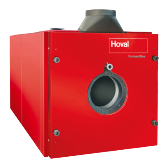
Technical details Description of the boiler The Hoval CompactGas is a low-pollution, energy saving gas boiler. The Hoval CompactGas has a horizontal com- bustion chamber as primary heating area and a second- ary heating area consisting of aluFer composite tubing. -
Page 14: Technical Data
TECHNICAL INFORMATION Technical data Type (700) (1000) (1400) (1800) (2200) (2800) • Nominal output at 80/60 °C 1000 1400 1800 2200 2800 • Range of output at 80/60 °C 250-700 300-1000 420-1400 540-1800 660-2200 840-2800 • Burner input maximum 1037 1458 1865 2280... - Page 15 TECHNICAL INFORMATION Type (3500) (4200) • Nominal output at 80/60 °C 3500 4200 • Range of output at 80/60 °C 1050-3500 1260-4200 • Burner input maximum 3626 4351 • Maximum working temperature °C • Minimum working temperature °C • Minimum boiler return temperature °C •...
-
Page 16: Dimensions / Space Required
TECHNICAL INFORMATION Dimensions / Space required 3.3.1 Dimensions (all dimensions in mm) Type k (inside) (700) 1100 1150 1175 4xM12 15˚/45˚ (1000) 1280 1330 1384 6xM12 15˚ (1400) 1480 1530 1584 6xM16 15˚ (1800) 1580 1630 1684 6xM16 15˚ (2200) 1580 1630 1684... -
Page 17: Base Size
TECHNICAL INFORMATION 3.3.2 Base size Dimensions without insulation and casing Boiler incl. boiler door, outlet without flue gas collector (dimensions in mm) Fig. 13 Type k (inside) (700) 1100 1436 1153 6xM12 15˚ (1000) 1280 1646 1363 6xM12 15˚ (1400) 1480 1886 1563... -
Page 18: Flue Gas And Output Diagrams
TECHNICAL INFORMATION Flue gas and output diagrams 3.4.1 Flue gas - output diagram 1400 2200 1800 1000 2800 3500 4200 1'000 1'200 1'400 1'600 1'800 2'000 2'200 2'400 2'600 2'800 3'000 3'200 3'400 3'600 3'800 4'000 4'200 Nominal output (kW) Values calculated without liability! kW = Boiler output •... -
Page 19: Installation
INSTALLATION Installation Flue gas connection, flue gas pipe, dimensions of flue gas pipe Safety notices To guarantee economic and fault-free operation, boiler CAUTION and chimney must be mutually adapted to create a func- tional unit. Danger of injury through sharp edges. Handle the cladding panels with care and avoid contact with sharp edges. - Page 20 INSTALLATION ref. a) If the integration of a transition element from the boiler Chimneys according to EN 13384, part 1/2, execution flue gas outlet to the chimney inlet is necessary, it should types I and II are appropriate for modern firing systems be executed as a slender cone.
-
Page 21: Installing The Burner
INSTALLATION Installing the burner Hydraulic connection • Burner installation dimensions may be obtained from In accordance with EN 12828:2003 the following safety point 3.3.2. devices are integrated in the boiler: • The burner is mounted on the boiler door by means - temperature regulator of the seal and screws. -
Page 22: Hydraulic Schematic
INSTALLATION 4.5.3 Hydraulic schematic Example CompactGas (700-2800) Gas boiler with - Free-standing calorifier • The examples stated below are principle - Wall distributor with 3 heating circuits schematics which do not contain all the de- tails for installation. The installation must be done according to the local conditions, di- NOTICE mensioning and regulations. -
Page 23: Electrical Connection
INSTALLATION Electrical connection A qualified technician must install the electri- cal supply to the equipment. The connection diagram is located in the elec- trical box of the heat generator; the circuit dia- gram is supplied separately. WARNING The heat generator can only be de-energised by disconnection from the mains (e.g. -
Page 24: Safety Measures Relating To Emc-Compliant Assembly
INSTALLATION 4.7.1 Safety measures relating • Equipotential bonding must be established between the individual control components, control panels and the to EMC-compliant assembly heating system. • Shielded cables must be used for the data lines. • Cables carrying mains voltage must be routed sepa- Recommended versions: rately from sensor or data bus cables. -
Page 25: Recommended Cable Cross Sections
1.0 mm unlimited m work are only allowed to be performed by the heat generator (400 V) with 10A fuse trained specialist personnel or by Hoval cus- Cables carrying mains min. 1.0 mm unlimited m tomer service. supply voltages... -
Page 26: Water Quality
In particular, attention must be paid to the following stipu- Filling and replacement water lations: • For a plant using Hoval boilers untreated drinking water • Hoval boilers and calorifi ers are designed for heating is generally best suited as heating medium, i.e. as fi ll- plants without signifi cant oxygen intake (plant type I ac- ing and replacement water. -
Page 27: Venting The Gas Pipes
COMMISSIONING Venting the gas pipes Observe the relevant regulations while vent- § ing the gas pipes • Open the gas stop valve. • Vent the gas pipe up to the gas armature. Handing over the plant to the operator The plant installer is responsible for providing instruction covering the entire plant. -
Page 28: Record - Activation Of Screed Function
COMMISSIONING Record - Activation of screed function Description of function The control module of the TopTronic E contains a functional sequence used for drying out screed fl oors. To start the ® screed drying, it is necessary for the individual functions to be set accordingly. Flow temperature Heating-up phase Inertia phase... - Page 29 COMMISSIONING Function display Icon Function Screed drying active Various settings can be made as well. Prioritisation of the screed func- tion means the settings are only ac- tive at the end of the function. Information remaining run time Request of the active function phase, the ACT temperature as well as the remaining run time.
-
Page 30: Maintenance
MAINTENANCE Maintenance Information for combustion controller/chimney sweep regarding emission monitor key This chapter is exclusively intended to describe the function of emissions and manual operation settings for the fi ring monitoring technician / chimney sweep. All operating elements are described in the operating instructions. CAUTION Danger of scalding with hot water, since the hot water temperature can exceed the target setpoint temperature. -
Page 31: Safety Notices
CAUTION Danger of injury for unqualified personnel. Servicing and Cleaning may only be carried out by qualified personnel or by Hoval cus- tomer service personnel. Venting • Open all radiator valves • Heat up plant for at least 12 hours with a high flow temperature. -
Page 32: Cleaning
MAINTENANCE Cleaning • Inadequate cleaning results not only in increased fuel consumption, but also shortens the service life of the boiler. The boiler must be cleaned by the chimney sweeper once a year. • Switch off the main switch Fig. 19 •... - Page 33 4 214 864 / 01...
- Page 34 COPY FOR PLANT USER Confirmation The user (owner) of the system herewith confi rms that • he has received adequate instruction in the operating and maintenance of the installation, • received and taken note of the operating and maintenance instructions and, where applicable other documents con- cerning the heat generator and any further components.
Need help?
Do you have a question about the CompactGas 700 and is the answer not in the manual?
Questions and answers