Table of Contents
Advertisement
Technical information
Assembly instructions
Oil/gas heating boilers
Max-3 plus (420-2700)
Hoval products must be installed and commissioned
tions are intended exclusively for the specialist. Electri-
electrician.
4 214 283 / 00 - UK - 03/15
Max-3 plus boilers are suitable and approved as
-
heat pro ducers for hot water heating systems with
permissible feed temperatures up to 110 °C
are designed fo
1)
see point 3.2
These instructions are applicable to the fol-
lowing types:
1-Max-3 plus (420)
1-Max-3 plus (530)
1-Max-3 plus (620)
1-Max-3 plus (750)
1-Max-3 plus (1000)
1-Max-3 plus (1250)
2-Max-3 plus (1500)
2-Max-3 plus (1800)
2-Max-3 plus (2200)
2-Max-3 plus (2700)
closed systems according to EN 12828.
r
. They
1)
EN
Advertisement
Table of Contents

Subscribe to Our Youtube Channel
Related Manuals for Hoval Max-3 plus Series


Summary of Contents for Hoval Max-3 plus Series
- Page 1 2-Max-3 plus (1800) 2-Max-3 plus (2200) 2-Max-3 plus (2700) Hoval products must be installed and commissioned Max-3 plus boilers are suitable and approved as heat pro ducers for hot water heating systems with tions are intended exclusively for the specialist. Electri- permissible feed temperatures up to 110 °C...
-
Page 2: Table Of Contents
TABLE OF CONTENTS Important information Other instructions ................................4 Safety information ................................4 Regulations, official approvals ............................4 Guarantee .................................... 5 Assembly Installing, levelling, boiler plinth ............................5 2.1.1 Installation of the regulators Max-3 plus (420-2700) ................ - Page 3 TABLE OF CONTENTS 4.15 Gas Boosters ..................................29 4.15.1 Booster Installation ................................. 29 Commissioning Water quality ..................................31 Filling the heating system ..............................32 Filling the calorifier ................................32 Commissioning .................................. 32 5.4.1 Commissioning Report ..........................
-
Page 4: Important Information
Depending on the application, any additional instructio- • IGE/UP/10 Installation of flued gas appliances in indus- ns can be found in the Hoval installation handbook! In trial and commercial premises. some cases the instructions are enclosed with the sep- •... -
Page 5: Guarantee
40 cm to the left and right hand sides of the boiler. Hoval Engineers will normally commission the boiler and if the heating engineer is present at the time, he will be instructed on the day-to-day operation of the boiler. If this... - Page 6 4. Mount the burner plug connector on the other side. Boiler door hinges must be changed over only by The cable must not contact any hot parts. Hoval Service! Figure shows situation as delivered (boiler door opens to the right) Fig.
-
Page 7: Mounting The Thermal Insulation Max-3 Plus (420-750)
ASSEMBLY 4 214 283 / 00... - Page 8 ASSEMBLY 4 214 283 / 00...
-
Page 9: Mounting The Cladding And Boiler Control Max-3 Plus (420-750)
ASSEMBLY 4 214 283 / 00... - Page 10 ASSEMBLY 4 214 283 / 00...
-
Page 11: Mounting The Thermal Insulation Max-3 Plus (1000-1250)
ASSEMBLY 4 214 283 / 00... - Page 12 ASSEMBLY 4 214 283 / 00...
-
Page 13: Mounting The Cladding And Boiler Control Max-3 Plus (1000,1250)
ASSEMBLY 4 214 283 / 00... - Page 14 ASSEMBLY 4 214 283 / 00...
-
Page 15: Mounting The Thermal Insulation Max-3 Plus (1500-2700)
ASSEMBLY 4 214 283 / 00... - Page 16 ASSEMBLY 4 214 283 / 00...
-
Page 17: Mounting The Cladding And Boiler Control Max-3 Plus (1500-2700)
ASSEMBLY 4 214 283 / 00... - Page 18 ASSEMBLY 4 214 283 / 00...
-
Page 19: Technical Information
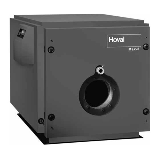
TECHNICAL INFORMATION Technical information Description of the boiler The Max-3 plus boiler is a three pass design. The flue gases flow from the cylindrical combustion chamber into the water cooled reversing elbows and through the second pass compartment into the front reversing chamber. The th- ird pass compartment comprises a bank of special dimpled Rillenrohre tubes through which the flue gases are con- ducted to the flue gas collector. -
Page 20: Technical Data Max-3 Plus (420-2700)
Maximum safety temperature for boiler control U3.1: 110 °C; for U3.2 : 120 °C. Flow resistance boiler in mbar = volume flow (m /h) x z Excludes weight of burner. Possible operating conditions: l i o ° ° Return temperature control (not by Hoval) 4 214 283 / 00... - Page 21 Maximum safety temperature for boiler control U3.1: 110 °C; for U3.2 : 120 °C. Flow resistance boiler in mbar = volume flow (m /h) x z Excludes weight of burner. Possible operating conditions: l i o ° ° Return temperature control required required (not by Hoval) 4 214 283 / 00...
-
Page 22: Dimensions Max-3 Plus (420-1250)
TECHNICAL INFORMATION Dimensions Max-3 plus (420 -1250) (Dimensions in mm) Dimensions Max-3 plus (1500-2700) (Dimensions in mm) 1 Flow (420-530) DN 100, PN 6 2 Return (420-530) DN 100, PN 6 Flue gas outlet (620-750) DN 125, PN 6 (620-750) DN 125, PN 6 Cleaning opening (1000-1250) -
Page 23: Dimensions Without Thermal Insulation And Casing Max-3 Plus (420-2700)
TECHNICAL INFORMATION Dimensions without thermal insulation and casing Max-3 plus (420-2700) (Dimensions in mm) 1 Flow 2 Return 3 Flue gas outlet 4 Drain Max-3 plus Type 1920 1770 2222 1060 1180 1060 1376 2077 1072 (420-530) 2195 2045 2498 1180 1300 1180... -
Page 24: Installation
The pressurisation unit control should also be interlo- In ALL cases the necessary ventilation to the Hoval Max-3 cked with the boiler(s) controls to safely close the burner plus boiler must be in line with the requirements set out in down in the event of malfunction. -
Page 25: Fan Dilution Systems - General Guidelines
) . C u r r e n t regulations for NOx limits (1993) are maximum 260 mg/kWh (148ppm IMPORTANT A condensate trap must also be fitted on at 0% O2). Burners supplied with Hoval boilers fully the boiler flue outlet to prevent condensa- meet this requirement. te entering the boiler. -
Page 26: Installing The Burner Max-3 Plus
INSTALLATION Installing the burner Max-3 plus Type (420-530) Type (620-2700) 15˚ 60˚ 45˚ 15˚ Type (420–530) Type (620–750) 4 x M12 (45°) 6 x M12 (15°) 4 x M12 (15°) Type (1000–2700) 6 x M16 (15°) Opening of the boiler door boiler door opens to the right or left (Dimensions in mm) Dimensions... -
Page 27: Combustion Chamber S E T S I N A E C X A L P S U
Seal this gap with the ceramic strip The boiler will normally be supplied by Hoval complete supplied. with a burner which is CE marked and is CE approved •... -
Page 28: Fuel
INSTALLATION Fuel Important! A single phase 230V supply is required for the control panel operation. Single phase The boiler is only to be operated with the fuel stated burners are electrically supplied via the on the boiler rating plate. control panel. Three phase burners requi- re a separate three phase isolated supply Max-3 plus boilers are normally suitable for burning the (by the installer) direct to the burner, in-... -
Page 29: Minimum Value Limiting Of Boiler Return Temperature
INSTALLATION Minimum value limiting of boiler return temperature Hydraulic and technical control measures are to be imple- Flue gas mented to ensure that the minimum boiler feed and return temperature sensor temperatures are not fallen below. Setting the temperature controller Boiler temperature controller, selectable TR 65-85°C The basic setting is made by the heating installer. - Page 30 INSTALLATION • Before running the booster the machine should be cle- • For the same reasons, connecting pipework needs to aned thoroughly, taking particular care to make sure be accurately aligned and properly supported. The use that pulleys and the belt are free from abrasive dust etc, which may have settled on the machine during in- booster and pipework is strongly recommended.
-
Page 31: Commissioning
• Filling and replacement water cording to EN 14868). • For a plant using Hoval boilers untreated drinking water ing and replacement water. However, as not all drinking • Plants with - continuous oxygen intake (e.g. underfloor heating systems without diffusion proof plastic piping) or - intermittent oxygen intake (e.g. -
Page 32: Filling The Heating System
• controls are proved and stats are adjusted in line with Hoval Service Engineers normally commission all temperature indicated on the boiler thermometer. new boilers and they will check the following: •... -
Page 33: Commissioning Report
COMMISSIONING 5.4.1 Commissioning Report All settings both on boiler and burner will be recorded on a commissioning report which will be supplied to the cus- tomers representative. Fig. 23 Hand-over to the user/safe-keeping Obtain from the user a written statement that operating and maintenance instructions have been explained to him and he has received the relevant operating instruc- tions (see page 60 for a standard statement). -
Page 34: Maintenance
OVERVIEW OF SETTINGS Maintenance Information for combustion controller/chimney sweep regarding emission monitor key All other control elements of the control unit are described in the operating instructions. The emission monitor key can also be used to change over to manual operating mode. Emission monitor key / Manual operation against invalid overheating during emis- sion monitoring / manual operation it is... -
Page 35: Operating Instructions
OVERVIEW OF SETTINGS Operating Instructions Sequencing of boilers under BMS control. When a bank of boilers are sequenced to operate un- der the dictates of a BMS control system, it is very im- PLEASE READ: Important Notes for the portant that on-line boilers are properly matched to Boiler Attendant the available heating load at any one time. -
Page 36: Inspection & Servicing
OVERVIEW OF SETTINGS Inspection & Servicing • which may be drawn into the burner and cause dama- red to carry out work other than the following: boiler • Examine all fuel and water valves, connection and bur- cleaning, inspection of components for damage, star- ner etc, for obvious signs of damage or leakage, and for security. -
Page 37: Boiler & Burner Servicing
Hoval. Any serious damage must be reported to the Service Engineer for repair. Filler 2. Switch OFF electrical supply to the burner. Where a material can be repaired similarly. -
Page 38: Summer Shut Down
OVERVIEW OF SETTINGS 13. Check boiler door is effectively closed (ineffective • Starting and Stopping closure will be detectable by sight or smell). • Emergency Stop 14. It is recommended that, when the boiler has beco- The burner can be stopped in an emergency by switching off the mains isolating switch provided on the made by the Service Engineer. - Page 39 OVERVIEW OF SETTINGS • Motor Keep the burner motor clean and dry. Any deposits of dust or lint should be blown out occasionally. On motors provided with oiling holes, a few drops of high quality SAE 20 oil should be injected every six months. Surplus lubricant spreading from the bearings should be wiped away.
-
Page 40: Oil Burner Fault Finding Chart
OVERVIEW OF SETTINGS Oil Burner Fault Finding Chart NOTE: Symptom Possible Cause Action Check the following: Burner will not start Electrical supply failure a. Main isolating switch of the bur- ner is on. b. Overload protective device of the burner motor. Control thermostat time or water Check that power is available at the pressure switches or other boiler... - Page 41 OVERVIEW OF SETTINGS Symptom Possible Cause Action Air inlet damper accidently masked 1. Clear obstruction. mes from burner. Flame shape alters from nor- mal. Boiler door beco- mes hotter than usual. Alteration to air inlet damper Reset damper and make a com- sition.
-
Page 42: Gas Burner Fault Finding Chart
OVERVIEW OF SETTINGS Gas Burner Fault Finding Chart NOTE: Symptom Possible Cause Action E lectrical supply failure Check: Burner will not start a. Main isolator switch is on and power is available at the control panel. b. Overload protective devices of Air pressure switch on burner not Switch contacts must be in the bur- operating. - Page 43 OVERVIEW OF SETTINGS Symptom Possible Cause Action Burner lights on pilot but Ultra-violet cell faulty As B3 burner locks out after 3 - Ultra-violet cell is not receiving a 2. Clean cell and check correctly in- 4 seconds. Smell of gas local to the Leakage from pipe line joints or pi- Switch OFF burner and check pipe appliance.
-
Page 44: Cleaning
OVERVIEW OF SETTINGS Cleaning Inadequate cleaning not only results in increased fuel consumption but also shortens the life of the boiler. The boiler is to be cleaned by a specialist twice a year • Switch off the main switch • Remove burner plug and switch off the fuel supply •... -
Page 45: Adjusting The Hinged Flange
OVERVIEW OF SETTINGS Adjusting the hinged flange After a long period of use, the contact pressure between boiler doors and boiler body can diminish. This impairs The boiler is therefore to be periodically checked for leaks Procedure: With the boiler door closed, screw lock nut (1, Fig. 27) forward and tighten;... -
Page 46: Overview Of Settings Table Of Parameters
OVERVIEW OF SETTINGS Overview of settings Table of parameters Regulator Setting range / Designation Factory Setting values Type of device: DHW: Address: Surface operation Key : Heating curve HC OFF, 0,20 ..3,5 Heating curve MC1 OFF, 0,20 ..3,5 Heating curve MC2 OFF, 0,20 .. - Page 47 OVERVIEW OF SETTINGS Table for Time programs DHW circuit Time program P1 Time program P2 Time program P3 Cycle 1 Cycle 2 Cycle 3 Cycle 1 Cycle 2 Cycle 3 Cycle 1 Cycle 2 Cycle 3 from from from from from from from...
- Page 48 OVERVIEW OF SETTINGS HYDRAULIC Par. Designation Factory Lev. Function allocation of the output DHW charging pump Function allocation of the output Mixer circuit 1 Function allocation of the output Mixer circuit 2 Function allocation of the output Direct circuit Pump Function allocation of the variable output 1 Function allocation of the variable output 2 OFF/ 4/ 43...
- Page 49 OVERVIEW OF SETTINGS Par. Designation Factory Lev. DHW-NIGHT DHW - economy temperature 40/ 45 °C DHW-legionella protection-day DHW-egionella protection-time 2:00 50/ 55/ 65/ DHW-legionella protection-temperature 70 °C DHW-temperature recording 50/ 55/ 65/ DHW-maximum temperature limit 70 °C DHW-mode of operation DHW-tank discharge protection ON/ OFF DHW-charging temperature excess...
- Page 50 OVERVIEW OF SETTINGS MIX. VALVE-1 Par. Designation Factory Lev. Type of reduced operation ECO/ ABS Heating system (exponent) MK= 1,10 Room override (in connection with room sensor) Room factor 100 % Adaptation heating curve Switch-on optimisation Heating limit Room frost protection limit 10 °C Room thermostat function Outside temperature allocation...
- Page 51 OVERVIEW OF SETTINGS MIX. VALVE-2 Par. Designation Factory Lev. Type of reduced operation ECO/ ABS Heating system (exponent) MK= 1,10 Room override (in connection with room sensor) Room factor 100 % Adaptation heating curve Switch-on optimisation Heating limit Room frost protection limit 10 °C Room thermostat function Outside temperature allocation...
- Page 52 OVERVIEW OF SETTINGS HEAT GENER. Par. Designation Factory Lev. H-GEN model 1/ 2/ 5 Start-up protection H-GEN OFF/ 3 5/ 48/ 65/ 75 Minimum temperature limit H-GEN °C Maximum temperature limit H-GEN 75/ 85 °C Mode of action minimum temperature limit H-GEN Sensor mode operation for H-GEN Minimum burner running time 2 min...
- Page 53 OVERVIEW OF SETTINGS RETURN CONTR Par. Designation Factory Lev. Minimum limit return temperature / reference value return 38 °C temperature Switch-off difference Pump follow-on time 1 min SOLAR Par. Designation Factory Lev. Switch-on difference 10 K Switch-off difference Minimum running time SOP 3 min Solar collector maximum temperature 100 °C...
- Page 54 OVERVIEW OF SETTINGS BUFFER Par. Designation Factory Lev. Minimum temperature 5/ 20 °C Maximum temperature 95 °C Temperature elevation, H-GEN 8/ 10/ 12K Switching difference 2/ 5/ 10K Forced discharge Skimming function switch-on difference 10 K Skimming function switch-off difference Start-up protection Discharge protection Buffer mode of operation...
- Page 55 OVERVIEW OF SETTINGS SERVICE Par. Designation Factory Lev. Service 1 (Cleaning ST1 ) Suspend message «CLEANING ST-1» for X days Cleaning according to cleaning counter Reset cleaning display 1 Service 2 (Cleaning ST2) Suspend message «CLEANING ST-2» for X days Cleaning according to cleaning counter Reset cleaning display 2 Service 3 (maintenance ST1 )
- Page 56 OVERVIEW OF SETTINGS FAULT REPORTING OVERVIEW TopTronic ® Status Designation Fault type Code Remark System External sensor Interruption 10-0 System External sensor Short-circuit 10-1 System Boiler sensor Interruption 11-0 System Boiler sensor Short-circuit 11-1 System Flow sensor 1 Interruption 12-0 MC1=off, YK1=no current System Flow sensor 1...
- Page 57 Regulator with address 10 is System Activity 70-8 missing System Activity Data bus error 70-9 No Hoval regulator System HP return sensor Return min. temp. below setpoint 85-4 System HP return sensor Return max. temp. exceeded 85-5 Heat source min. temp. below...
- Page 58 Hoval Limited, Northgate, Newark, Notts NG24 1JN Telephone: 01636 593413 Fax: 01636 673532 e-mail: spares@hoval.co.uk or service@hoval.co.uk Web Site: www.hoval.co.uk Hoval follows a policy of continued improvement and reserves the right to change specifications without notice. 4 214 283 / 00...
- Page 59 4 214 283 / 00...
- Page 60 COPY FOR PLANT USER Confirmation The user (owner) of the system herewith con rms that • he has received adequate instruction in the operating and maintenance of the installation, • received and taken note of the operating and maintenance instructions and, where applicable other documents con- cerning the heat generator and any further components.
Need help?
Do you have a question about the Max-3 plus Series and is the answer not in the manual?
Questions and answers