Table of Contents
Advertisement
Technical information
Assembly instructions
UltraGas
(250D-2000D)
®
Condensing gas heating boilers
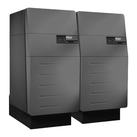
Hoval double boiler
Hoval products must be installed and commissioned
only by appropriately qualified experts. These instruc-
tions are intended exclusively for the specialist. Elec-
trical installations may only be carried out by a qualified
electrician.
Subject to modifi cations
|
4 210 527 / 03 - 10/13
Rated output levels at 40/30ºC and for
natural gas
30-UltraGas
®
30-UltraGas
®
30-UltraGas
®
30-UltraGas
®
30-UltraGas
®
30-UltraGas
®
30/31-UltraGas
30/31-UltraGas
30/31-UltraGas
30/31-UltraGas
30/31-UltraGas
30/31-UltraGas
30-UltraGas
®
30-UltraGas
®
The floor standing gas condensing boiler UltraGas
(250D-2000D) are designed and approved for use as
heat generators for hot water heating systems with a
permissible flow temperature of up to 90 ºC
cordance with EN 483 and EN 677. They are designed
for continuously adjustable reduced output operation in
heating systems.
see section technical data
1)
(250D)
28 - 246 kW
(300D)
28 - 300 kW
(400D)
44 - 400 kW
(500D)
49 - 500 kW
(600D)
57 - 600 kW
(700D)
58 - 700 kW
(800D)
97 - 800 kW
®
(900D)
97 - 900 kW
®
(1000D)
97 - 1000 kW
®
(1150D)
136 - 1150 kW
®
(1300D)
136 - 1300 kW
®
(1440D)
142 - 1440 kW
®
(1700D)
166 - 1700 kW
(2000D)
224 - 2000 kW
, in ac-
1)
EN
®
Advertisement
Table of Contents

Subscribe to Our Youtube Channel
Related Manuals for Hoval 30-UltraGas (250D)


Summary of Contents for Hoval 30-UltraGas (250D)
- Page 1 ® 30-UltraGas (2000D) 224 - 2000 kW ® Hoval products must be installed and commissioned The floor standing gas condensing boiler UltraGas ® only by appropriately qualified experts. These instruc- (250D-2000D) are designed and approved for use as tions are intended exclusively for the specialist. Elec-...
-
Page 2: Table Of Contents
TABLE OF CONTENTS Safety instructions Key to symbols used ................................3 Assembly Procedure way ..................................3 Technical Information Dimensions ..................................4 Space requirements ................................5 Technical data UltraGas (250D-700D) ..........................7 ® Technical data UltraGas (800D-1300D) ..........................8 ® Technical data UltraGas (1440D-2000D) ..........................9 ® Boiler flow resistence ................................10 Installation Room air-dependent Installation............................ -
Page 3: Safety Instructions
• Operating instructions 3. See separate instructions for the mounting of the flue It is imperative for the boiler commission- gas overpressure set! ing to be carried out by a Hoval service engineer or a trained Hoval partner. 4. Optional: Mounting of the hydraulic pipeline connection set (common flow and return). -
Page 4: Technical Information
..11 Boiler foot adjustable up to 20-80mm ........ Notes: Data for pipe connection (option) to Hoval UltraGas (250D-2000D) For detailed measurements and measurements for installation as in- ® * DN = nominal diameter , PN = nominal pressure, S = number of screw,... -
Page 5: Space Requirements
TECHNICAL INFORMATION Space requirements (All dimensions in mm) For swing out of burner this clearance must be ensured Install gas line straight to the back with hydraulic connection set UltraGas ® Type A minimal H minimal (250D, 300D) 1770 1237 981 1823 1711 (400D-600D) - Page 6 TECHNICAL INFORMATION UltraGas with shortened boiler feet ® (All dimensions in mm) UltraGas ® Type (250D, 300D) 1723 - 1783 (400D - 600D) 1823 - 1883 (700D - 1000D) 1970 - 2030 (1150D - 1440D) 1986 - 2046 (1700D, 2000D) 2039 - 2099 1 Neutralisation box 2 Condensate pump...
-
Page 7: Technical Data Ultragas ® (250D-700D)
TECHNICAL INFORMATION Technical data UltraGas (250D-700D) ® Type (250D) (300D) (400D) (500D) (600D) (700D) • Nominal output 80/60 °C with natural gas 25-226 25-276 39-370 44-454 51-546 51-636 • Nominal output 40/30 °C with natural gas 28-246 28-300 44-400 49-500 57-600 58-700 •... -
Page 8: Technical Data Ultragas ® (800D-1300D)
TECHNICAL INFORMATION Technical data UltraGas (800D-1300D) ® Type (800D) (900D) (1000D) (1150D) (1300D) • Nominal output 80/60 °C with natural gas 87-728 87-820 87-910 122-1048 122-1184 • Nominal output 40/30 °C with natural gas 97-800 97-900 97-1000 136-1150 136-1300 • Nominal output 80/60 °C with propane gas 139-728 139-820 139-910... -
Page 9: Technical Data Ultragas ® (1440D-2000D)
TECHNICAL INFORMATION Technical data UltraGas (1440D-2000D) ® Type (1440D) (1700D) (2000D) • Nominal output 80/60 °C with natural gas 127-1310 148-1552 199-1824 • Nominal output 40/30 °C with natural gas 142-1440 166-1700 224-2000 • Nominal output 80/60 °C with propane gas 169-1310 •... -
Page 10: Boiler Flow Resistence
TECHNICAL INFORMATION Boiler flow resistence UltraGas (250D, 300D) UltraGas (400D-600D) ® ® [mbar] [mbar] one boiler flowing one boiler flowing both boiler flowing both boiler flowing UltraGas (700D-1000D) UltraGas (1150D-1440D) ® ® [mbar] [mbar] one boiler flowing one boiler flowing both boiler flowing both boiler flowing Volumenstrom [m3/h] UltraGas (1700D, 2000D) ® [mbar] one boiler flowing both boiler flowing /h = Through put flow rate mbar = Flow resistance 4 210 527 / 03... -
Page 11: Installation
INSTALLATION Installation Room air-dependent Installation No binding values for the size of the intake air apertures are quoted in most relevant regulations. The sole require- ment is that no vacuum occurs in the boiler room in ex- cess of 3 N/mm Room air-independent Installation The UltraGas twin boilers are fitted with intake flaps. An... -
Page 12: Flue Gas Line Dimensions (Overpressure)
INSTALLATION Flue gas line dimensions (overpressure) Principles • Height above sea level max. 1000 m. • The first 2 m of the flue gas line are to be executed in the same dimensions as the flue gas connectors. • Combustion air: - In the case of room air-independent operation (ac- cessories optional) the air pipe must be at least the same dimension as the flue gas pipe. -
Page 13: Hydraulic Connection
INSTALLATION Hydraulic connection • Ensure that the boilers are in each case connected in the Tichelmann system. • Please comply with separate installation instructions if the optional hydraulic set is used. • When using the high temperature-return, install this so that the connection socket is located on the same size (see chapter 3.1). -
Page 14: Application Without Main Pump (System Kba010)
INSTALLATION 4.6.2 Application without main pump (system KBA010) Boiler sequential controller circuit double boiler by TTT TopTronic T TopTronic T VF 2 VF 2 VF 3 V F4 V F4 M K 1 M K 2 M K 2 M K 3 M K 4 M K 4 Y10.1... - Page 15 INSTALLATION Kessel 2, boiler 2, caldaia 2, chaudière 2 400V Versorgung ab UltraGas 1000 erforderlich BUS-Verbindung zu Klemmen Kessel 1,2,... , Alimentation de 400V nécessaire à partir de l'UltraGas 1000 BUS-Connection to terminal block boiler 1,2, ..., 400V di alimentazione, richiesti a partire dall'UltraGas 1000 BUS-Collegamento a morsettiera pompa di caldaia 1,2,...
-
Page 16: Application Without Main Pump (System Kba020)
INSTALLATION 4.6.3 Application without main pump (system KBA020) Boiler sequential controller circuit double boiler by GLT 1 x 0-10V module operating both boilers Temperature control 0-10V TopTronic T TopTronic T Modul Y10.1 Y10.2 Dies Dies unerlaubter Weg! unerlaubter Weg! Gehen einen Gehen einen... - Page 17 INSTALLATION Kessel 1, boiler 1, caldaia 1, chaudière 1 400V Versorgung ab UltraGas 1000 erforderlich BUS-Verbindung zu Klemmen Kessel 1,2,... , Alimentation de 400V nécessaire à partir de l'UltraGas 1000 BUS-Connection to terminal block boiler 1,2, ..., 400V di alimentazione, richiesti a partire dall'UltraGas 1000 BUS-Collegamento a morsettiera pompa di caldaia 1,2,...
- Page 18 INSTALLATION Kessel 2, boiler 2, caldaia 2, chaudière 2 400V Versorgung ab UltraGas 1000 erforderlich BUS-Verbindung zu Klemmen Kessel 1,2,... , Alimentation de 400V nécessaire à partir de l'UltraGas 1000 400V di alimentazione, richiesti a partire dall'UltraGas 1000 BUS-Connection to terminal block boiler 1,2, ..., 400V supply required from UltraGas 1000 BUS-Collegamento a morsettiera pompa di caldaia 1,2,...
-
Page 19: Application Without Main Pump (System Kba030)
INSTALLATION 4.6.4 Application without main pump (system KBA030) Boiler sequential controller circuit double boiler by GLT 2 x 0-10V modul operating each boiler separately Power control 0-10V 0-10V TopTronic T TopTronic T Modul Modul Y10.1 Y10.2 Dies Dies unerlaubter Weg! unerlaubter Weg! Gehen einen... - Page 20 INSTALLATION Kessel 1, boiler 1, caldaia 1, chaudière 1 400V Versorgung ab UltraGas 1000 erforderlich Alimentation de 400V nécessaire à partir de l'UltraGas 1000 400V di alimentazione, richiesti a partire dall'UltraGas 1000 400V supply required from UltraGas 1000 230V / 10AT 3 x 400V / 10AT Netz/Power supply Netz /Power supply...
- Page 21 INSTALLATION Kessel 2, boiler 2, caldaia 2, chaudière 2 400V Versorgung ab UltraGas 1000 erforderlich Alimentation de 400V nécessaire à partir de l'UltraGas 1000 400V di alimentazione, richiesti a partire dall'UltraGas 1000 400V supply required from UltraGas 1000 230V / 10AT 3 x 400V / 10AT Netz/Power supply Netz /Power supply...
-
Page 22: Application With Main Pump (System Kbb010)
INSTALLATION 4.6.5 Application with main pump (system KBB010) Boiler sequential controller circuit double boiler by TTT TopTronic T TopTronic T VF 2 V F2 V F3 M K 1 M K 2 M K 2 M K 3 M K 4 M K 4 Y10.1 Y10.2... - Page 23 INSTALLATION Kessel 2, boiler 2, caldaia 2, chaudière 2 400V Versorgung ab UltraGas 1000 erforderlich BUS-Verbindung zu Klemmen Kessel 1,2,... , Alimentation de 400V nécessaire à partir de l'UltraGas 1000 400V di alimentazione, richiesti a partire dall'UltraGas 1000 BUS-Connection to terminal block boiler 1,2, ..., 400V supply required from UltraGas 1000 BUS-Collegamento a morsettiera pompa di caldaia 1,2,...
-
Page 24: Application With Main Pump (System Kbb020)
INSTALLATION 4.6.6 Application with main pump (system KBB020) Boiler sequential controller circuit double boiler by GLT 1 x 0-10V module operating both boilers Temperature control 0-10V TopTronic T TopTronic T Modul Y10.1 Y10.2 SVLF M5.1 M5.2 Dies Dies unerlaubter Weg! unerlaubter Weg! Gehen einen... - Page 25 INSTALLATION GLT Modul 0-10V (im Kessel 1, in boiler 1, in caldaia 1, en chaudière 1) Temperaturregelung extern mit 0 - 10 V (V in1) : External temperature control with 0 - 10 V (V in1) : Regolazione temperatura esterno con 0- 10 V (V in1) : Régulation externe de la température avec 0 - 10 V (V in1): Interne Verdrahtung / Internal electrical wiring / 0 - 1 V ...
- Page 26 INSTALLATION PARAMETER /PARAMETER /PARAMETRO /PARAMETRE: SW ≧ 3.1 OPTION / OPZIONE: 1) Minimalwertbegrenzung: REGLER 10, CONTROLER 10, REGLER 20, CONTROLER 20, Minimum flow temperature limit: REGULATORE 10, REGULATEUR 10 REGULATORE 20, REGULATEUR 20 Limitazione minima temperatura: Limite de la température minimale: HYDRAULIK / HYDRAULIC / SYSTEM / SYSTEM / 2) WW-Überhöhung: IDRAULICA / HYDRAULIQUE:...
-
Page 27: Application With Main Pump (System Kbb030)
INSTALLATION 4.6.7 Application with main pump (system KBB030) Boiler sequential controller circuit double boiler by GLT 2 x 0-10V modul operating each boiler separately Power control 0-10V 0-10V TopTronic T TopTronic T Modul Modul Y10.1 Y10.2 M5.1 M5.2 Dies Dies unerlaubter Weg! unerlaubter Weg! Gehen... - Page 28 INSTALLATION Kessel 1, boiler 1, caldaia 1, chaudière 1 400V Versorgung ab UltraGas 1000 erforderlich Alimentation de 400V nécessaire à partir de l'UltraGas 1000 400V di alimentazione, richiesti a partire dall'UltraGas 1000 400V supply required from UltraGas 1000 230V / 10AT 3 x 400V / 10AT Netz/Power supply Netz /Power supply...
- Page 29 INSTALLATION Kessel 2, boiler 2, caldaia 2, chaudière 2 400V Versorgung ab UltraGas 1000 erforderlich Alimentation de 400V nécessaire à partir de l'UltraGas 1000 400V di alimentazione, richiesti a partire dall'UltraGas 1000 400V supply required from UltraGas 1000 230V / 10AT 3 x 400V / 10AT Netz/Power supply Netz /Power supply...
-
Page 30: 4.6.8 Legend
INSTALLATION 4.6.8 Legend 4 210 527 / 03... - Page 31 4 210 527 / 03...
- Page 32 Conservation of Energy - Protection of the Environment...
Need help?
Do you have a question about the 30-UltraGas (250D) and is the answer not in the manual?
Questions and answers