Table of Contents
Advertisement
Technical information
Installation instructions
UltraOil
(16-35)
®
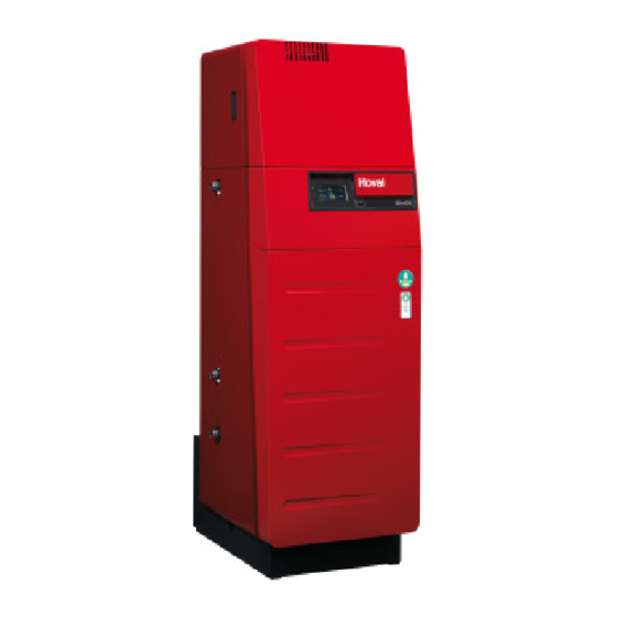
Oil condensing boiler
This appliance is
only suitable for
operation with
heating oil EL
(low sulphur)
Hoval products must be installed and commissioned
only by appropriately qualified experts. These instruc-
tions are intended exclusively for the specialist. Elec-
trical installations may only be carried out by a qualified
electrician.
Subject to modifi cations
|
4 213 784 / 00 - 02/15
These instructions are applicable to the
following types:
Rated output levels at 40/30 ºC
41-UltraOil
(16)
®
41-UltraOil
(20)
®
41-UltraOil
(25)
®
41-UltraOil
(35)
®
with TopTronic
The 41-UltraOil
heating boiler is suitable for and ap-
®
proved as a heating unit for hot-water systems with
permitted flow temperatures up to 90 °C
ned primarily for closed circuits, but is equally suitable
for installation in open circuits.
see point 3.2
1)
E controller
®
. It is desig-
1)
EN
Advertisement
Table of Contents

Related Manuals for Hoval UltraOil


Summary of Contents for Hoval UltraOil
- Page 1 This appliance is only suitable for operation with heating oil EL (low sulphur) Hoval products must be installed and commissioned The 41-UltraOil heating boiler is suitable for and ap- ® only by appropriately qualified experts. These instruc- proved as a heating unit for hot-water systems with tions are intended exclusively for the specialist.
-
Page 2: Table Of Contents
Boiler room requirements ..............................19 Flue gas connection and chimney ............................19 4.2.1 Project planning instructions ............................19 Example of a flue gas conduit (Hoval flue gas system) ........................20 Fuel ....................................20 Electrical connection .................................21 4.5.1 Safety measures relating to EMC assembly ........................22 Flue gas performance diagrams ............................23... - Page 3 TABLE OF CONTENTS Maintenance Information for combustion controller/chimney sweep regarding emission monitor key ..........29 Renewing fuse ...................................30 Cleaning the boiler and leakage test ..........................30 6.3.1 Preparations for cleaning the boiler and burner .......................30 6.3.2 Re-assembling the boiler ..............................30 6.3.3 Cleaning the combustion chamber and the aluFer pipes ....................32 ®...
-
Page 4: Important Information Other Instructions
All instructions relevant to your system can be found in formation of scale in hot water systems. the Hoval system manual! In exceptional cases, the inst- • DIN 57 116 / VDI 0116 Electrical equipment in combus- ructions can be found in the documentation for the com- tion systems (VDE regulations). -
Page 5: Assembly
ASSEMBLY Assembly Fitting the burner 1. Remove the absorber hood (1, Fig. 02), after first re- Set-up, levelling leasing the lateral locking bolt (2) (turn approx. ¼ turn The boiler is fixed to wooden transport chocks. For trans- to the left and pull out as far as the stop). port up and down stairs, it is wise to leave these timbers in place under the boiler. - Page 6 ASSEMBLY Assembly aid: To simplify installation, the sealing on the burner flange can be lubricated using a heat-resistant paste (e.g. Kluberpaste UH1 84-201). Screw head Fig. 06 6. Fix the burner in position by tightening the screw (3, Fig. 03). Fill the cavity between burner pipe and boiler door with the fireproof fibre provided.
- Page 7 ASSEMBLY 7. Close the boiler flange with the burner again. 8. The oil lines can be routed through the absorber hood on the right or left side. 9. Establish the plug-in connections (4, Fig. 08). Pull the plug cables out further by releasing the high-strength cable glands (5).
-
Page 8: Condensate Discharge
ASSEMBLY Condensate discharge Possibility 3 -see chapter 2.6 • Siphon and condensate delivery pump • Without neutralisation, condensate discharge into high- The condensate discharge must be ma- er drain line. nufactured of corrosion-resistant materi- al. The following materials are suitable for the condensate discharge: PVC, PE, PP, ABS Local regulations pertaining to the con-... -
Page 9: Fitting The Condensate Drain (Standard Design)
ASSEMBLY Fitting the condensate drain (standard 5. Fit drain (5) on siphon (3) and lead it outwards (optio- nally left or right side) through the aperture (5a). design) 6. Fit connecting line (5) to the drain line (2m hose enc- 1. -
Page 10: Fitting The Neutralisation Box (Option)
ASSEMBLY Fitting the neutralisation box (Option) 5. Fit jubilee clip (5) approx. 20mm from the upper end of the hose and tighten slightly. The hose (5a) of the 1. Remove the neutralisation box from its packaging. connection eccentric (5b) must be aligned towards Remove the front and rear cover of the neutralisation the left. -
Page 11: Fitting The Condensate Delivery Pump (Option)
ASSEMBLY Fitting the condensate delivery pump (Op- tion) Install the condensate delivery pump (11, Fig. 22) as shown in the drawing. Fig. 19 8. Slightly loosen the jubilee clip (8, Fig. 20) and push it upwards. Firmly tighten the jubilee clip (connection must be sealed). -
Page 12: Fitting The Neutralisation Box And The Condensate Delivery Pump (Option)
ASSEMBLY Fitting the neutralisation box and the con- 3. Remove front cover (2a, Fig. 25). Release lateral lo- cking bolt (2) (turn approx. ¼ to the left and pull out as densate delivery pump (option) far as the stop). Lift the front cover straight upwards and remove towards the front. - Page 13 ASSEMBLY 7. Slide the neutralisation box (6, Fig. 27) into the boiler 10. Fill the neutralisation box with water. until the hose of the siphon (5a, Fig. 26) is directly 11. Fit the front cover (9, Fig. 30) of the neutralisation beneath the drain connection.
-
Page 14: Fitting The Flue Gas Silencer (Option)
ASSEMBLY Fitting the flue gas silencer (Option) The silencer must be installed vertically. The maximum permissible angle of incli- nation is 45°! Fig. 31 4 213 784 / 00... -
Page 15: Technical Information
Substitute measures can be used in the case of boilers with an output of up to 300 kW. On boilers of type UltraOil (16-35), the safety disconnec- tion function during operation without water was tested. The test was performed successfully. -
Page 16: Technical Data
Data without sound absorber. Reduction by installation of a sound absorber possible Depending on the number of controller modules/module expansions fitted, there is an increase in the max. electrical power consumption. Flue gas silencer Connection Diameter to Hoval UltraOil on both sides Total length external Attenuation... -
Page 17: Dimensions Ultraoil (16-35)
TECHNICAL INFORMATION Dimensions UltraOil (16-35) ® (All dimensions in mm) Heating flow / safety flow R1" Low-temperature return R1" High-temperature return R1" Flue gas outlet DN80 Control panel Fig. 33 Condensate drain (left or right) incl. siphon DN25 and 2 m PVC continuous-flow tube inner Ø 19 x 4... -
Page 18: Space Requirement Ultraoil (16-35)
TECHNICAL INFORMATION Space requirement UltraOil (16-35) ® min. 50 mm with silencer Fig. 34 Boiler door incl. burner swings upward and to the left or outward. minimal 150 mm * Brennerserviceposition vorne - Kesselreini- gung von rechts optimum 300 mm *... -
Page 19: Installation
120 °C. Not dependent upon room air • The flue gas system must be suitable for operation at As a unit of type C53 or C63, the UltraOil can be set up ® pressure. -
Page 20: Example Of A Flue Gas Conduit (Hoval Flue Gas System)
Inspektions-T- - Eco heating oil low-sulphur SN 181 160-2 / 2008 T-piece Stück einzusetzen If an existing oil heating installation is replaced by a Hoval UltraOil , the following instructions regarding the oil tank ® and its refilling must be observed:... -
Page 21: Electrical Connection
INSTALLATION Electrical connection 1. Remove noise damping cover (1, Fig. 37). Release lateral locking bolt (2) (approx. ¼ turn to the left). 2. Remove front cover (3) Release lateral locking bolt A qualified technician must install the (4) (approx. ¼ turn to the left). electrical supply to the equipment. -
Page 22: 4.5.1 Safety Measures Relating To Emc Assembly
INSTALLATION Cable grip Protect all cables against strain with the enclosed cable grips when the controller is folded open. Mains supply 230V Fig. 38 Controller modules are only connected with 3 lines (no +) of the bus system. Control modules are connected with 4 li- nes because these have to be supplied. -
Page 23: Flue Gas Performance Diagrams
INSTALLATION Flue gas performance diagrams The diagrams show the flue gas temperature characteristics with Hoval burners. UltraOil (16) ® Flow 80 °C/ return flow 60 °C Flow 40 °C/ return flow 30 °C °C °C UltraOil (20) ® Flow 80 °C/ return flow 60 °C Flow 40 °C/ return flow 30 °C... -
Page 24: Hydraulic Integration
120 kW drained together with domestic waste water from a private household. For the UltraOil , the fuel used must be hea- ® ting oil EL low-sulphur. As a rule, neutralisati- on of the condensate is not necessary. -
Page 25: Commissioning
8.3 and 9.5 after 6-12 weeks of heating operation. In particular, attention must be paid to the following stipu- lations: • Hoval boilers and calorifi ers are designed for heating Filling and replacement water plants without signifi cant oxygen intake (plant type I ac- cording to EN 14868). -
Page 26: Filling The Heating System
COMMISSIONING Filling the heating system Filling of the heating system must be carried out by trai- ned personnel. The fill and make-up water must com- ply with the quality requirements in the relevant state or country (see chapter 5.1). Filling the water heater (if fitted) The heating boiler may be put into operation even when the water heater is not filled. -
Page 27: Record - Activation Of Screed Function
COMMISSIONING Record - Activation of screed function Description of function The control module of the TopTronic E contains a functional sequence used for drying out screed fl oors. To start the ® screed drying, it is necessary for the individual functions to be set accordingly. Flow temperature Heating-up phase Inertia phase... - Page 28 COMMISSIONING Function display Icon Function Screed drying active Various settings can be made as well. Prioritisation of the screed func- tion means the settings are only ac- tive at the end of the function. Information remaining run time Request of the active function phase, the ACT temperature as well as the remaining run time.
-
Page 29: Maintenance
MAINTENANCE Maintenance Information for combustion controller/chimney sweep regarding emission monitor key This chapter is exclusively intended to describe the function of emissions and manual operation settings for the fi ring monitoring technician / chimney sweep. All operating elements are described in the operating instructions. Danger of scalding with hot water, since the hot water temperature can exceed the target setpoint temperature. -
Page 30: Renewing Fuse
For a detailed ® tenance contract with Hoval customer service, or with an description of how to clean the combustion chamber authorised specialist dealer. and the aluFer pipes, see chapter 6.3.3. - Page 31 MAINTENANCE Fig. 41 Design with condensate discharge Design with neutralisation box (if fitted) Mount hose for Fig. 42 Fig. 43 wet cleaning 4 213 784 / 00...
-
Page 32: Cleaning The Combustion Chamber And The Alufer ® Pipes
• A special cleaning set (contains four cleaning scrap- ers) to remove stubborn dirt build-up is available from Hoval, Art. No. 6022 844. • Before removing the drain hose, all dirt particles must be adequately rinsed out of the condensate drip tray. -
Page 33: Servicing The Neutralisation Installation (If Fitted)
Neutralisation granulate for refi lling can be ordered from Hoval under the following item no.: • 1 pack (3 kg) neutralisation granules Part no. 2028 906 Procedure for servicing the neutralisation installation •... -
Page 34: Safety Temperature Limiter - Reset
MAINTENANCE Safety temperature limiter - Reset If the boiler temperature rises too high (>100 °C), the system is switched off by the safety temperature limiter (STL) by means of a mechanical lockout. The malfunction must first be unlocked on the safety temperature limiter, then on the control panel. 1. - Page 35 4 213 784 / 00...
- Page 36 COPY FOR PLANT USER Confirmation The user (owner) of the system herewith confi rms that • he has received adequate instruction in the operating and maintenance of the installation, • received and taken note of the operating and maintenance instructions and, where applicable other documents con- cerning the heat generator and any further components.
Need help?
Do you have a question about the UltraOil and is the answer not in the manual?
Questions and answers