Table of Contents
Advertisement
Technical information
Installation instructions
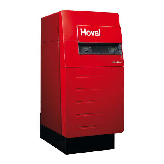
UltraGas
(125-1000)
®
Condensing gas heating boilers
for natural gas and liquid gas
for modulating operation
Hoval products must be installed and commissioned
only by appropriately qualified experts. These instruc-
tions are intended exclusively for the specialist. Electri-
cal installations may only be carried out by a qualified
electrician.
Subject to modifi cations
|
4 210 267 / 04 - 10/13
Rated output levels at 40/30ºC and for
natural gas
30-UltraGas
®
30-UltraGas
®
30-UltraGas
®
30-UltraGas
®
30-UltraGas
®
30-UltraGas
®
30/31-UltraGas
30/31-UltraGas
30/31-UltraGas
30/31-UltraGas
30/31-UltraGas
30/31-UltraGas
30-UltraGas
®
30-UltraGas
®
The floor standing gas condensing boiler UltraGas
(125-1000) are designed and approved for use as
heat generators for hot water heating systems with a
permissible flow temperature of up to 90°C
ance with EN 483 and EN 677. They are designed for
continuously adjustable reduced output operation in
heating systems.
see technical data
1)
(125)
28 - 123 kW
(150)
28 - 150 kW
(200)
44 - 200 kW
(250)
49 - 250 kW
(300)
57 - 300 kW
(350)
58 - 350 kW
(400)
97 - 400 kW
®
(450)
97 - 450 kW
®
(500)
97 - 500 kW
®
(575)
136 - 575 kW
®
(650)
136 - 650 kW
®
(720)
142 - 720 kW
®
(850)
166 - 850 kW
(1000)
224 - 1000 kW
), in accord-
1
EN
®
Advertisement
Table of Contents

Related Manuals for Hoval UltraGas Series


Summary of Contents for Hoval UltraGas Series
- Page 1 ® 30-UltraGas (1000) 224 - 1000 kW ® Hoval products must be installed and commissioned The floor standing gas condensing boiler UltraGas ® only by appropriately qualified experts. These instruc- (125-1000) are designed and approved for use as tions are intended exclusively for the specialist. Electri-...
-
Page 2: Table Of Contents
Safety instructions Key to symbols used ..........................4 Important notes Acceptance of delivery .......................... 5 Scope of guarantee ..........................5 Instruction manuals ..........................5 Regulations, official permits ........................5 2.4.1 Germany ..............................6 2.4.2 Austria ............................... 6 2.4.3 Switzerland ............................... 6 Assembly Placement .............................. -
Page 3: Table Of Contents
Maintenance Safety information ..........................41 Bleeding ..............................41 Water refilling ............................41 Information for combustion controller/chimney sweep regarding emission monitor key ..... 42 Cleaning ..............................43 7.5.1 Cleaning the burner cylinder (inside and outside) ................... 43 7.5.2 Cleaning the exterior of the combustion chamber and burner cylinder ..........44 7.5.3 Cleaning/adjusting the ignition and ionisation device ................ -
Page 4: Safety Instructions
Safety instructions The system shall not be put into operation until all relevant standards and safety regulations are met. For a test run, the following minimum conditions must be satisfied: - Safety valve installed (closed system) - Controls operative (connected to power supply) - Sensor for safety temperature limiter is connected (= boiler temperature sensor) - System filled with water... -
Page 5: Important Notes
- corrosion through nonconforming water quality Instruction manuals A summary of all the instruction manuals relevant to this system can be found in the Hoval System User Guide! In exceptional cases the instructions are kept with the respective components! Additional sources of information:... -
Page 6: Germany
§ 2.4.1 Germany DIN EN 12831 Heating systems in buildings - Methods for calculating the design heat load DIN EN 13384 Flue gas systems - Heat and flow calculation methods DIN EN 12828 Heating systems in buildings - Planning of hot water heating systems. DIN 4755 Oil fired combustion systems. -
Page 7: Assembly
Assembly Placement Space requirements UltraGas (125-1000) ® Make sure that the cable does not touch any hot locations! Dimensions (mm) For swing out of burner this clearence must be ensured Install gas line straight to the back Fig. 01 UltraGas ®... - Page 8 UltraGas with shortened boiler feet ® (All measurements in mm) UltraGas ® Type (125, 150) 1723 - 1783 (200 - 300) 1823 - 1883 (350 - 500) 1970 - 2030 (575 - 720) 1986 - 2046 (850, 1000) 2039 - 2099 1 Neutralisation box 2 Condensate pump 3 Masonry base...
- Page 9 Procedure: 1. Remove the two upper threaded elements (1) on the boiler base (1a). 2. Take off the front wooden beam. 3. Raise the front of the boiler with a jack (3). 4. Move aside the side beam (4) at the front (see fig. 2) Introduce the front feet and screw in place. 5.
-
Page 10: Mounting Of Heat Insulation
Mounting of heat insulation 1. Place the insulation blanket (1) around the UltraGas boiler and fix with plastic bands (1a) and clips (1b) ® - tension springs (1c) are used for additional fixing - do not fit the band too tightly (reduces insulation value). Fig. -
Page 11: Mounting The Casing
Mounting the casing 1. Attach the cable channels (2) left and right to the pins and fix with the hexagon nuts and washers (3a, fig. 4a) already mounted to the boiler. Turn side wall supports (2b, fig. 4b) laterally to the outside. 2. - Page 12 Secure service platform (7c, fig. 4d) in folded-up position using bolt (1b, fig. 3)! S e i t e n w a n d s t ü t z e 2 1 - U l t r a G a s ( 8 5 0 ) Illustrated without burner Fig.
- Page 13 Types (850,1000) two-pieces Type (125,720) one-piece Burner wiring Type (125-850); 2 connector plugs Type (1000); 3 connector plugs Boiler tempe- rature sensor Ignition cable Flue gas sensor Line cord Condensate box Water pressure (if available) sensor Fig. 04 4 210 267 / 04 Assembly...
-
Page 14: Mounting Of Base Casing
Mounting of base casing Mount the siphon (13) delivered loose, incl. double nipple (13a, fig. 5). 2. Position the condensate box (option) under the boiler and make the electrical connection. Create con- densate outlet, resp. connection line according to separate instructions. For UltraGas (575,650,720,850,1000): ®... -
Page 15: Adjusting The Length Of The Ladder Types (850,1000)
Fig. 06 Adjusting the length of the ladder types (850,1000) only type UG (850,1000) If the option with shortened boiler feet is being applied or if the boiler is put on a concrete base, the ladder supplied must be shortened (cut away at the notch) resp. -
Page 16: Technical Information
The Hoval UltraGas has a vertically utilised for the heating circuit. The gas burner is in the ®... -
Page 17: Technical Data
Wobbe coefficient of 12.0 up to 15.7 kWh/m is possible (a readjustment may be necessary). See also notes at „Engineering“. Details for multi-boiler plants (cascade) with common flue gas line: see Hoval UltraGas ® (250D-2000D). • Boiler flow resistence see separate page. - Page 18 Wobbe coefficient of 12.0 up to 15.7 kWh/m is possible (a readjustment may be necessary). See also notes at „Engineering“. Details for multi-boiler plants (cascade) with common flue gas line: see Hoval UltraGas (250D-2000D).. ® • Boiler flow resistence see separate page.
- Page 19 Wobbe oefficient of 12,0 up to 15,7 kWh/m is possible (a readjustment may be necessary). See also notes at „Engineering“. Details for multi-boiler plants (cascade) with common flue gas line: see Hoval UltraGas (250D-2000D). ® * Data unknown at time of printing •...
-
Page 20: Dimensions / Space Requirements
Ø247/250 * DN = nominal diameter, PN = nominal pressure, example DN65 / PN6 / 4 screws Important: An automatic air vent (AAV) must be fitted before any isolation valve. This is not provided by Hoval. Technical information 4 210 267 / 04... -
Page 21: Opening Dimension
4.3.1 Opening dimension Boiler without casings and insulation wrap UltraGas ® Measurements for installation as individual parts Type (125,150) 1520 1072 1295 1380 1191 1040 (200-300) 1585 1422 1330 1355 1445 1260 1390 (350) 1610 1530 1420 1380 1450 1272 1480 (400-500) 1810... -
Page 22: Hydraulic Resistance
Hydraulic resistance UltraGas (125, 150) UltraGas (200-300) ® ® 9 10 11 12 13 14 15 Volumenstrom [m3/h] Volumenstrom [m3/h] Through put flow rate [m3/h] Through put flow rate [m3/h] UltraGas (350-500) UltraGas (575-720) ® ® 10 15 20 25 30 35 40 45 50 55 60 65 Volumenstrom [m3/h] Volumenstrom [m3/h] Through put flow rate [m3/h]... -
Page 23: Brief Description Of The Automatic Firing Device
Brief description of the automatic firing device The automatic firing device BIC960 of the UltraGas only operates in conjunction with the heating controller ® TopTronic T/UG. For this reason, the automatic firing device only needs to take care of the last remaining ®... -
Page 24: Installation
Installation Safety information Caution! Sharp edges pose a cutting hazard. Handle the casing parts with care and avoid contact with sharp edges. Boiler room requirements § The boiler room must satisfy the applicable local building regulations. § The boiler room ventilation must satisfy the applicable local regulations in this regard. Boilers may not be installed in rooms containing halogen compounds which can be car- §... -
Page 25: Flue Gas Connection And Flue
Flue gas connection and flue Due to the low flue gas temperatures, condensate forms within the flue. For this reason, HOVAL gas heating boilers can not be connected to conventional house chimneys. § The flue gas extraction system must comply with the following directives: DVGW (TRGI) ÖVGW... -
Page 26: Condensate Drainage
Condensate drainage The condensate drainage pipes on the boiler must be made of corrosion resistant material. The following materials are suitable for condensate drainage: The local regulations regarding condensate drainage must be observed. 5.4.1 Execution variants The siphon needs to be instal-led and filled with water before start- ing up the system. -
Page 27: Gas Connection
Variant 5 UltraGas on base without adjustable feet ® The siphon needs to be instal- led and filled with water before starting up the system. The siphon is filled with water through the cleaning aperture. Neutralisation box Condensate pump: Art. Nr. 6015159 Base bricked Condensate pump free standing, with or without high-altitude neutralisation box... -
Page 28: Customer-Side Requirements
5.6.3 Cascade control As a basic principle, the Hoval TopTronic should perform cascade control. This en- sures an environmentally and product-friendly method of operation. However, if an external cascading strategy is planned and boiler performance control is carried out, frequent cycles should be avoided (at least 12 minutes burner running time is required between cycles). -
Page 29: Electrical Connection
Electrical connection Procedure to remove the front covering panel 1. Remove front cover (1, fig. 23a), after first releas- ing the lateral locking bolt (1a) (turn approx. ¼ - The electrical connection must be car- turn to the left and pull out as far as the stop). Lift ried out by an approved electrician. -
Page 30: Commissioning
Fill the heating system slowly. Monitor the water level on the manometer. Use only chemical additives with suppliers’ confirmation of their safe usage. If frost protection agent is being used, please contact the Hoval company to ask for the separate engineering sheet. Commissioning... -
Page 31: Water Quality
8.3 and 9.5 after 6-12 weeks of heating operation. In particular, attention must be paid to the following stipu- lations: • Hoval boilers and calorifi ers are designed for heating Filling and replacement water plants without signifi cant oxygen intake (plant type I ac- cording to EN 14868). -
Page 32: Bleeding The Air From The Gas Line
Bleeding the air from the gas line § Observe the relevant regulations when bleeding the gas line Open the gas shut-off valve. Bleed the air up to the gas armature. Switching on the system Switch on the main switch. Gas inlet pressure The gas flow may only be adjusted and the heating system therefore started up, if the minimum flow pressure values are achieved (see section 6.7 Adjusting the gas flow). -
Page 33: Setting The Gas Flow Rate Co ) And Measurement Of Nox/Co Content In The Flue Gas
Setting the gas flow rate CO ) and measurement of NOx/CO content in the flue 6.7.1 Flue gas measurement UltraGas (125-720) ® Screwdriver, allen key 3 mm, TorxT40 The Honeywell multiple actuator allows measuring the inlet pressure on measuring nipple A. A Measuring nipple gas inlet pressure B Impulse pipe connector C Gas choke... -
Page 34: Flue Gas Measurement Ultragas (850,1000)
6.7.2 Flue gas measurement UltraGas (850,1000) ® Screwdriver, allen key 2,5 mm The Dungs multiple actuator allows measuring the ® inlet pressure on measuring nipple A. A Measuring nipple gas inlet pressure B Impulse pipe connector C Gas choke D Offset screw Use step boards! (see point 7.5.1) Flow setting operation:... -
Page 35: Changing Over To A Different Gas Type
Changing over to a different gas type This changeover may only be carried out by an authorised specialist or by the HOVAL Customer Service. Changeover from natural gas H to natural gas L An emission check is required when changing to a natural gas of lower calorific value;... - Page 36 For UltraGas (400-720) ® only approved for propane 1. With boiler already connected: - close the gas shut-off valve - place the system switch in the operating panel to “0” 2. Take off the boiler hood Fit the aperture aperture The conversion kit contains: Yellow sticker Aperture with seal...
-
Page 37: Type (850,1000) Setting For The Stabilisation Damper (If Necessary)
Type (850,1000) Setting for the stabilisation damper (if necessary) The stabilisation damper reduces the outlet cross-section of the fan during the start- up phase. This optimises the start-up characteristics of the boiler! Factory setting for the stroke: 20 mm. This is the optimum setting under normal flue conditions. If even stronger compression is required, the stroke can be set to a maximum of 22.5 mm using the setscrew. -
Page 38: Handover To The User
6.10 Handover to the user The manufacturer of the unit is responsible for providing operating instructions for the complete system. The following must be carried out during handover to the user: Provide instructions in the operation and maintenance of the system. Handover of all the instruction manuals and documents. -
Page 39: Record - Activation Of Screed Function
6.11 Record - Activation of screed function Cross where applicable; cut out record and fasten to the control during the active screed function. Minimum requirements for the activation of the screed function: Minimum age cement screed 21 days Minimum age calcium sulphate screed 7 days Flow temperature monitor installed and connected For newly laid screed - see „Recommendation of the Federal Association of Radiant Panel Heating“. - Page 40 Parameter 16 „Screed function“ (Parameter HC, MC1 or MC2) Example: Maximum fl ow temperature 40°C 1 Function heating Starting day + 7 days [°C] VLSol 55°C maximum set level! maximal 55°C einstellbar! 1=Funktionsheizen 1 = Function heating Funktionsheizen START DAYS START 1 9 10 11 12 13 14 15 16 17 18 19 20 21 22 23 24 25 26 TAGE] START 1...
-
Page 41: Maintenance
Caution! Danger of injury for unqualified personnel. Maintenance and cleaning work may only be performed by trained personnel or by the Hoval Customer Service. Caution! After repair work respectively exchanging boiler parts, a flue gas measurement according to point 6.7 must be carried out imperatively. -
Page 42: Information For Combustion Controller/Chimney Sweep Regarding Emission Monitor Key
Information for combustion controller/chimney sweep regarding emission monitor key All other control elements of the control unit are described in the operating instructions. The emission monitor key can also be used to change over to manual operating mode. Emission monitor key / Manual operation To protect under fl... -
Page 43: Cleaning
The HOVAL gas heating boiler should be cleaned and maintained once every year. If the HOVAL gas heating boiler was in operation during the building phase, it will be necessary to carry out a check for cleanliness. If the boiler is dirty, clean it. -
Page 44: Cleaning The Exterior Of The Combustion Chamber And Burner Cylinder
7.5.2 Cleaning the exterior of the combustion chamber and burner cylinder Warning! Chemical burn hazard through cleaning agents. Safety gloves and eye protection must be worn when using cleaning agents. Observe the information on the original packaging. Caution! The system can be damaged when using incorrect cleaning agents. Use only cleaning agents approved for gas boilers with aluminium components. -
Page 45: Cleaning/Adjusting The Ignition And Ionisation Device
Cleaning : Spray the combustion chamber and aluFer tubes (3, fig. 13). ® The best results are obtained with a spray gun with a suitable wide jet nozzle (fan or conical jet). We recommend, e.g.: • Desoxin Leave the applied cleaning agent to react as instructed by the manufacturer. Then remove the contamination on the combustion chamber and aluFer tubes by ®... - Page 46 Check all electrode distances and reset where necessary (see fig. 14 and 15). Procedure to readjust: Heat the ignition electrode at the kink with the blowtorch until it glows red. Bend the ignition electrode with the long-nosed pliers until the required distance is set.
-
Page 47: Setting The Gas Flow Rate Co
Setting the gas flow rate CO ) and measurement of NOx/CO content in the flue (according to point 6.7) Clean siphon • Loosen siphon and remove from boiler. • Rinse siphon. • Check if siphon gaskets (1) are not damaged, replace if necessary. Caution: poisoning! 21-UltraGas (850) If siphon is not filled with water or if it is contaminated or obstructed by contami-... - Page 48 Neutralisation granulate for refi lling can be ordered from Hoval under the following item no.: • 1 pack (3 kg) neutralisation granules Part no. 2028 906 One fi lling requires 4 packs of 3 kg each.
-
Page 49: Overview Of Settings
Overview of settings Table of parameters Regulator Setting range / Designation Factory Setting values Type of device: DHW: Address: Surface operation Key : Heating curve HC OFF, 0,20 ..3,5 Heating curve MC1 OFF, 0,20 ..3,5 Heating curve MC2 OFF, 0,20 .. - Page 50 Table for Time programs DHW circuit Time program P1 Time program P2 Time program P3 Cycle 1 Cycle 2 Cycle 3 Cycle 1 Cycle 2 Cycle 3 Cycle 1 Cycle 2 Cycle 3 from from from from from from from from from Direct circuit...
- Page 51 HYDRAULIC Par. Designation Factory Lev. Function allocation of the output DHW charging pump Function allocation of the output Mixer circuit 1 Function allocation of the output Mixer circuit 2 Function allocation of the output Direct circuit Pump Function allocation of the variable output 1 Function allocation of the variable output 2 OFF/ 4/ 43 Function allocation of the variable input 1...
- Page 52 Par. Designation Factory Lev. DHW-NIGHT DHW - economy temperature 40/ 45 °C DHW-legionella protection-day 2:00 DHW-egionella protection-time 50/ 55/ 65/ DHW-legionella protection-temperature 70 °C DHW-temperature recording 50/ 55/ 65/ DHW-maximum temperature limit 70 °C DHW-mode of operation ON/ OFF DHW-tank discharge protection DHW-charging temperature excess 7/ 20 K DHW-switching difference...
- Page 53 MIX. VALVE-1 Par. Designation Factory Lev. Type of reduced operation ECO/ ABS MK= 1,10 Heating system (exponent) Room override (in connection with room sensor) Room factor 100 % Adaptation heating curve Switch-on optimisation Heating limit Room frost protection limit 10 °C Room thermostat function Outside temperature allocation Constant temperature reference value...
- Page 54 MIX. VALVE-2 Par. Designation Factory Lev. Type of reduced operation ECO/ ABS MK= 1,10 Heating system (exponent) Room override (in connection with room sensor) Room factor 100 % Adaptation heating curve Switch-on optimisation Heating limit Room frost protection limit 10 °C Room thermostat function Outside temperature allocation Constant temperature reference value...
- Page 55 HEAT GENER. Par. Designation Factory Lev. H-GEN model 1/ 2/ 5 OFF/ 3 Start-up protection H-GEN 5/ 48/ 65/ 75 Minimum temperature limit H-GEN °C 75/ 85 °C Maximum temperature limit H-GEN Mode of action minimum temperature limit H-GEN Sensor mode operation for H-GEN Minimum burner running time 2 min Burner switching difference I...
- Page 56 AUTOMATIC FIRING DEVICE UltraGas (125-300) ® Designation Blocking temperature °C Maximum setpoint °C 2AD Switch-off hysteresis via setpoint °C Switching difference to switch-off point °C Proportional range °C 2AG Integral part 2AH Differential part Setpoint for bus interrupt °C Maximum temperature rise for low flow temperature °C/s Maximum temperature rise for high flow temperature °C/s...
- Page 57 AUTOMATIC FIRING DEVICE UltraGas (125-300) ® Designation Ignition (0-> internal, 1-> internal + external, 2-> external) 44 2KM Stepped modulation (0-> off, 1-> rising, 2-> rising and falling) Action mode fault relays 2NA ADC/4 value at 0 bar 2NB *ADC/4-value at 6/10 bar (V3) 145/ 145/ 145/...
- Page 58 AUTOMATIC FIRING DEVICE UltraGas (350-575) ® Designation 22 2DG Blocking pressure max - hysteresis 23 2DH Lock-out pressure max Max boiler output for pressure warning 2EC Ionisation warning µA Number of Hall pulses per rotation Fan speed first phase pre-vent 5600 3600 4000 4400 4200 –1 2FG Start rpm...
- Page 59 AUTOMATIC FIRING DEVICE UltraGas (650-1000) ® Designation Blocking temperature °C Maximum setpoint °C Switch-off hysteresis via setpoint °C Switching difference to switch-off point °C Proportional range °C Integral part Differential part Setpoint for bus interrupt °C Maximum temperature rise for low flow temperature °C/s Maximum temperature rise for high flow temperature °C/s...
- Page 60 AUTOMATIC FIRING DEVICE UltraGas (650-1000) ® Designation Fan speed first phase pre-vent 4800 4800 4700 5600 –1 Start rpm 1600 1600 1700 1700 –1 4800 4800 4700 5600 Maximum fan speed –1 Minimum fan speed –1 1000 1000 1200 Fan ramp-up during purge /s OEM –1 Fan ramp-down during purge...
- Page 61 RETURN CONTR Par. Designation Factory Lev. Minimum limit return temperature / reference value return 38 °C temperature Switch-off difference Pump follow-on time 1 min SOLAR Par. Designation Factory Lev. 10 K Switch-on difference Switch-off difference Minimum running time SOP 3 min Solar collector maximum temperature 100 °C Solar tank maximum limit (KSPF)
- Page 62 BUFFER Par. Designation Factory Lev. Minimum temperature 5/ 20 °C 95 °C Maximum temperature 8/ 10/ 12K Temperature elevation, H-GEN Switching difference 2/ 5/ 10K Forced discharge Skimming function switch-on difference 10 K Skimming function switch-off difference Start-up protection Discharge protection Buffer mode of operation 2/ 3 Pump follow-on time...
-
Page 63: Fault Reporting Overview Toptronic
SERVICE Par. Designation Factory Lev. Service 1 (Cleaning ST1 ) Suspend message «CLEANING ST-1» for X days Cleaning according to fi xed date Cleaning according to fi xed interval Cleaning according to cleaning counter Reset cleaning display 1 Service 2 (Cleaning ST2) Suspend message «CLEANING ST-2»... - Page 64 FAULT REPORTING OVERVIEW TopTronic ® Status Designation Fault type Code Remark System External sensor Interruption 10-0 System External sensor Short-circuit 10-1 System Boiler sensor Interruption 11-0 System Boiler sensor Short-circuit 11-1 System Flow sensor 1 Interruption 12-0 MC1=off, YK1=no current System Flow sensor 1 Short-circuit...
-
Page 65: Automatic Firing Device (Warning, Blocking, Lock-Out)
Regulator with address 10 is System Activity 70-8 missing System Activity Data bus error 70-9 No Hoval regulator System HP return sensor Return min. temp. below setpoint 85-4 System HP return sensor Return max. temp. exceeded 85-5 Heat source min. temp. below... - Page 66 Automatic firing device (Warning, Blocking, Lock-out) Failure Code Description Type W:01 Warning Water pressure too low W:02 Warning Ionisation too low B:03 Blocking Gas pressure too low/ Gas pressure switch defective/ external blockings B:04 Blocking *Main gas valve (possibly LPG- valve)/ Heating room fan B:05 Blocking Water pressure outside of limits...
- Page 67 4 210 267 / 04...
- Page 68 COPY FOR PLANT USER Confirmation The user (owner) of the system herewith confi rms that • he has received adequate instruction in the operating and maintenance of the installation, • received and taken note of the operating and maintenance instructions and, where applicable other documents con- cerning the heat generator and any further components.
Need help?
Do you have a question about the UltraGas Series and is the answer not in the manual?
Questions and answers