
Subscribe to Our Youtube Channel
Related Manuals for Hoval SR-plus 500


Summary of Contents for Hoval SR-plus 500
- Page 1 Operating and Installation Instructions for the SR-plus hot water boiler 0088 Issued By TECHNICAL DEPT Dated: August 2014 Approved...
-
Page 2: Table Of Contents
Boiler Efficiency Directive (92/42/EEC) Certification No. CE-0085 . Material in this publication may not be reproduced without the company's written permission. Hoval Ltd, Northgate, Newark, Notts, NG24 1JN, Tel: 01636 672711 Fax: 01636 673532 e-mail: service@hoval.co.uk Hoval reserve the right to change specifications without notice. -
Page 3: Introduction
I.E.E. Regulations, relevant British Standard and Codes of Practice, Building Regulations and Local Authority Bylaws. Commissioning/Combustion Report Hoval Engineers will normally commission the boiler and if the heating engineer is present at the time, he will be instructed on the day-to-day operation of the boiler. If this is not possible, or additional training is required, this can be arranged through Hoval. -
Page 4: Gas Safety(Installation & Use)
Failure to install appliances correctly could lead to prosecution. It is in your own interest, and that of safety, to ensure that the law is complied with. The Hoval SR-plus range, with both standard and low NOx burners, have been Certified against the requirements of prEN676 for natural gas. -
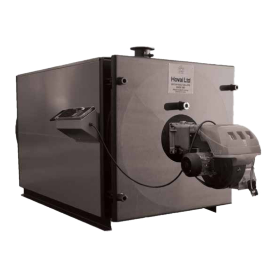
Page 5: Description Of The Sr-Plus Boiler
The hinged side door nuts are supplied with a locknut The third pass water jacketed gas passage ways with at the back of the door boss. Hoval should be advised turbulators provide an effective secondary heating of the door and gas burner handing when the boiler is surface. -
Page 6: Technical & Performance Details
SR-plus Technical & Performance Details SR-plus 500 - 1500 Type 1200 1500 • Maximum output 1000 1250 1500 • Minimum output • Boiler input at maximum output 546.45 656.50 818.77 1094.09 1366.12 1646.54 • Boiler input at minimum output 240.60 322.23... -
Page 7: Technical & Performance Details
SR-plus Technical & Performance Details Dimensions and Technical Information SR-plus heating boiler (models 500 to 900) Control panels are mounted on top of the boiler as standard up to SR-plus 900. Side mounting (left or right) can also be accommodated. Burner Burner Rear view... - Page 8 SR-plus Technical & Performance Details Dimensions and Technical Information SR-plus heating boiler (models 1200 to 4000) Control panel can be mounted on left or right hand side. Burner Burner Rear view Elevation view A single phase 230V supply is required for the control panel operation.
-
Page 9: Installation
Boiler Plant Noise Levels This is a specialist subject and where noise due to vibration, combustion or mechanical sources is likely to be a problem, Hoval should be advised. Measures can be adopted to reduce noise levels if it The following are sound and vibration control measures... -
Page 10: Ventilation
A safety valve should be installed in a tee piece as near to the boiler as possible with no intervening Hoval recommend that a Level Probe Switch is fitted valve. It should be sized to the relevant British in the flow pipe rising from the boiler. It should be Standard. -
Page 11: Flues & Chimneys
CIBSE and HVCA guides and also HovalTechnical In this case a vertical balanced flue can be helpful. Data Sheets. Flues should conform to the relevant Refer to Hoval for further details. British Standards, Codes of Practice etc. Fan Dilution Systems - General Guidelines... -
Page 12: Filling The System With Water/ Water Treatment
CIBSE/BSRIA guidelines. the effects of hardness salts and corrosion. Hoval advise contact directly with major specialists on water treatment such as Grace & Dearborn or Houseman.. August 2014... -
Page 13: Burner Matching , Fitting The Burner
Burner matching The boiler will normally be supplied by Hoval complete with a burner which is CE marked and is CE approved for firing with the boiler. Where it is required to fit an alternative burner, to comply with CE Directives, the boiler must only be used with a burner having CE marking in accordance with Directive 90/396/EEC and Standard EN 676 (Gas) or EN 267 (Oil). -
Page 14: Control Details
The control panel (as illustrated) is generally supplied for mounting on top of the boiler casing by the installer. For normal high/low operation the control stat is set by the Hoval commissioning engineer at the required lev- el e.g. 80 C . -
Page 15: Boosters
Installation - Gas Boosters Gas Boosters A booster is required when the gas pressure at the burner is below the value specified by the burner manufacturer at the flow rate attained at maximum burner rating. Important If a vital function is served, install a standby gas booster. -
Page 16: Commissioning
Commissioning Commissioning It is essential that the following points are completed by the Heating Engineer before commissioning is requested through Hoval. • System full of water and vented • Boiler flue box drain pipework is fitted • Spirals fitted where appropriate •... -
Page 17: Commissioning
Commissioning • commissioning is in accordance with burner makers requirements. • controls are proved and stats are adjusted in line with temperature indicated on the boiler thermometer. • that the boiler is fired up at a rate allowing the door refractory to reach a uniform temperature through its thickness thereby preventing any damage. -
Page 18: Operating Instructions, Including Sequencing Of Boilers Under Bms Control
Operating Instructions Operating Instructions Starting up after cleaning the boiler or PLEASE READ: Important Notes for the Boiler Attendant a Summer shut down. These instructions are the minimum necessary to enable an Ensure that fuel lines are fully purged and that fuel operator to start, run and stop the boiler. -
Page 19: Maintenance
Maintenance - Inspection & Servicing Inspection & Servicing A qualified boiler/burner service engineer will be required to carry out work other than the follow- ing: boiler cleaning, inspection of components for damage, starting up the boiler, and the specified testing and minor fault rectification. -
Page 20: Boiler & Burner Servicing
These checks must be made by a qualified boiler/burner service engineer, ideally under an annual sevice and maintenance contract. Hoval Service Department normally provides this service and will be pleased to provide a written quotation on request. This would typically cover the operation, cleanliness, combustion efficiency etc., of the fuel burner and associated controls. -
Page 21: Summer Shutdown
13) It is recommended that, when the boiler has in normal use but in the unlikely event please become thoroughly hot, a combustion efficiency consult Hoval. Any serious damage must be check is made by the Service Engineer. reported to the Service Engineer for repair. Filler material can be repaired similarly. -
Page 22: Burner Maintenance
Maintenance - Burners Burner Maintenance Before carrying out any work on the burner ensure that the main electrical isolating switch is Impor- in the OFF position and the fuel isolating valve closed. These instructions are provided for the benefit of the CAUTION: Do not place any items in the boiler combustion chamber as it is not operator and are intended to be of assistance in making... -
Page 23: Oil Burner Fault Finding Chart
Oil Burner Fault Finding Chart Oil Burner Fault Finding Chart NOTE: Rectification of any internal burner component must be done by a qualified burner engineer. Symptom Possible Cause Action Burner will not start 1. Electrical supply failure 1. Check the following: a) Main isolating switch of the burner is on. -
Page 24: Oil Burner Fault Finding Chart
Oil Burner Fault Finding Chart Oil Burner Fault Finding Chart / 2 Symptom Possible Cause Action Smok y flame and/or 1. Air inlet damper accidently 1. Clear obstruction. f u m e s f r o m b u r n e r. masked or other obstruction to Flame shape alters from airflow. -
Page 25: Gas Burner Fault Finding Chart
Gas Burner Fault Finding Chart Gas Burner Fault Finding Chart NOTE: Rectification of any internal burner component must be done by a qualified burner engineer. Symptom Possible Cause Action Burner will not start 1. Electrical supply failure. 1. Check: a) Main isolator switch is on and power is available at the control panel. - Page 26 Gas Burner Fault Finding Chart Gas Burner Fault Finding Chart / 2 Symptoms Possible Cause Action Burner lights on pilot but 1. Ultra-violet cell faulty 1. As B3 burner locks out after 3 - 4 seconds. 2. Ultra-violet cell is not receiving a 2.
- Page 27 Conservation of Energy Protection of the Environment Hoval Limited, Northgate, Newark, Notts NG24 1JN Telephone: 01636 672711 Fax: 01636 673532 e-mail: service@hoval.co.uk Web Site: www.hoval.co.uk...
Need help?
Do you have a question about the SR-plus 500 and is the answer not in the manual?
Questions and answers