Table of Contents
Advertisement
Quick Links
Technical information
Installation instructions
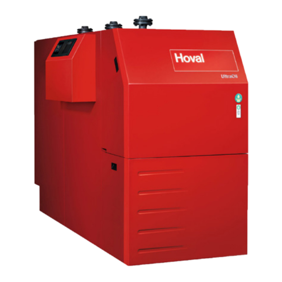
UltraOil
(110-300)
®
Oil condensing boiler
Hoval products may only be installed and commissi-
oned by appropriately qualified experts. These ins-
tructions are intended exclusively for the specialist.
Electrical installation must be performed by a licensed
electrical company.
Subject to modifi cations
|
4 214 858 / 01 - 04/20
These instructions apply to the following
types:
42-UltraOil
(110)
®
42-UltraOil
(130)
®
42-UltraOil
(160)
®
42-UltraOil
(200)
®
42-UltraOil
(250)
®
42-UltraOil
(300)
®
with TopTronic
This appliance is
only suitable for
operation with
heating oil EL
(low sulphur)
The UltraOil
boiler is designed and licensed for use
®
as a heat generator for hot water heating systems with
permissible flow temperatures of up to 90 °C
signed primarily for closed circuits, but is equally suita-
ble for installation in open circuits.
see point 3.2
1)
E controller
®
. It is de-
1)
EN
Advertisement
Table of Contents

Related Manuals for Hoval 42-UltraOil 110


Summary of Contents for Hoval 42-UltraOil 110
- Page 1 This appliance is only suitable for operation with heating oil EL (low sulphur) Hoval products may only be installed and commissi- The UltraOil boiler is designed and licensed for use ® oned by appropriately qualified experts. These ins- as a heat generator for hot water heating systems with tructions are intended exclusively for the specialist.
-
Page 2: Table Of Contents
TABLE OF CONTENTS Important information Safety instructions ................................4 1.1.1 Warnings ..................................4 1.1.2 Symbols ....................................4 Warranty ....................................5 Other instructions ................................5 Regulations, official approvals ............................6 Assembly Installation position, transport ............................7 2.1.1 Transport ..................................7 2.1.2 Vertical installation in case of space problems ........................7 Setting up, levelling ................................7 2.2.1 Boiler door pivotable to the left ............................8... - Page 3 TABLE OF CONTENTS Maintenance Information for combustion controller/chimney sweep regarding emission monitor key ..........33 Safety temperature limiter - Reset ............................34 Cleaning the boiler ................................35 6.3.1 Preparations for cleaning the boiler and burner .......................35 6.3.2 Re-assembling the boiler ..............................35 6.3.3 Cleaning the boiler room ..............................35 Cleaning the combustion chamber and the aluFer pipes ....................37 ®...
-
Page 4: Important Information Safety Instructions
IMPORTANT INFORMATION Important information 1.1.1 Warnings Safety instructions DANGER The system may only be put into operation if ... indicates a situation of immediate danger all relevant standards and safety regulations which will lead to serious or fatal injuries if have been complied with. -
Page 5: Warranty
Other instructions All instructions relevant to your system can be found in the Hoval system manual! In exceptional cases, the inst- ructions can be found in the documentation for the com- ponents! Further sources of information:... -
Page 6: Regulations, Official Approvals
IMPORTANT INFORMATION Regulations, official approvals Switzerland For installation and operation of the system, the following - VKF - Association of Cantonal Fire Insurers regulations must be observed: § - Fire prevention authority regulations - SN EN 12831 Heating systems in buil- Germany dings - Procedure for calculation of the standard heating load. -
Page 7: Assembly
2.1.2 Vertical installation in case of space problems the boiler door, incl. the burner. A special installation kit is available from Hoval for vertical installation (see chapter 3.5.2). To make it easier to transport into confined spaces, the There must always be enough space between... -
Page 8: Boiler Door Pivotable To The Left
ASSEMBLY 2.2.1 Boiler door pivotable to the left 1. Remove the top and bottom hinge nut (1, Fig. 01). 2. Fit the screw (2, Fig. 01) (pivot point) on the other It is possible to change the attachment of the boiler door side of the door. -
Page 9: Fitting The Thermal Insulation
ASSEMBLY Fitting the thermal insulation - there are also tension springs (4, Fig. 02) for addi- tional attachment 1. Check that the size of the right and left casing sup- - Do not pull the tapes too tight (this would reduce the port rail (1, Fig. -
Page 10: Fitting The Casing
ASSEMBLY Fitting the casing Installation of boiler control 1. Hook the electrical box (14, Fig. 07) into the side wall CAUTION (8, Fig. 07) with the recesses for the special screws The cable must not touch any hot parts. and secure it with two self-tapping screws Ø3.5x6.5 (13, Fig. - Page 11 ASSEMBLY 4 214 858 / 01...
-
Page 12: Installation Of Burner Cover
ASSEMBLY Installation of burner cover Cover front top UltraOil (110-200) ® - Installation sequence as per drawing Cover front bottom UltraOil (110-300) ® Fig. 10 Fig. 08 Cover front top UltraOil (250-300) ® Fig. 09 4 214 858 / 01... -
Page 13: Fitting The Siphon
ASSEMBLY Fitting the siphon Place the condensate box (option) (41, Fig. 11) behind the boiler and establish the electrical connection. WARNING Fit connecting line between siphon and condensate box. Attach the siphon (40, Fig. 11), which is sup- plied loose. Before commissioning, the siphon and the neutralisation box (if fitted) must be filled with water in order to prevent flue gas leakage. -
Page 14: Installation Of Burner
ASSEMBLY Installation of burner For installation of the burner see the enclosed 1. Open the boiler flange (4 locking screws) and check ”HO F30E1-2 / F35E1- 2 oil burner” installa- the installation position of the combustion chamber tion manual. unit. Don›t forget to insulate the intermediate spa- NOTICE ce between the burner tube and boiler flange... -
Page 15: Technical Information
® the following directives + standards Description of the boiler We hereby declare that the product described, as an in- The Hoval UltraOil is a low-pollutant and energy-saving ® dividual unit, complies with the standards, directives and oil-fired condensing boiler. It has a tilted combustion technical specifications listed. -
Page 16: Technical Data
TECHNICAL INFORMATION Technical data Type (110) (130) (160) • Nominal output 80/60 °C • Nominal output 40/30 °C • 78 - 105.0 99 - 124.0 114 -152.0 Range of output 80/60 °C 83 - 110.0 104 - 130.0 119 -160.0 •... - Page 17 TECHNICAL INFORMATION Type (200) (250) (300) • Nominal output 80/60 °C • Nominal output 40/30 °C 133 - 190 180 - 238 215 - 286 • Range of output 80/60 °C 140 - 200 189 - 250 227 - 300 •...
-
Page 18: Dimensions Ultraoil (110-300)
TECHNICAL INFORMATION Dimensions UltraOil (110-300) ® (All dimensions in mm) Return Flow Fig. 15 UltraOil (110-200) UltraOil (250,300) ® ® Flow heating/safety flow DN 65/PN 6 DN 65/PN 6 Low temperature return DN 65/PN 6 DN 65/PN 6 High temperature return DN 65/PN 6 DN 65/PN 6 Flue gas outlet (plastic) -
Page 19: Space Requirements Ultraoil (110-300)
TECHNICAL INFORMATION Space requirements UltraOil (110-300) ® (All dimensions in mm) Fig. 16 * Important: there must be 700 mm space on the left or right of the boiler so that the boiler door can be swivelled out with the burner. UltraOil (110-160) 2353... -
Page 20: Opening Dimension Ultraoil (110-300)
TECHNICAL INFORMATION Opening dimension UltraOil (110-300) ® 3.5.1 Mass without thermal insulation and casing (All dimensions in mm) Fig. 17 UltraOil (110-160) 1524 1882 1362 1533 ® UltraOil (200) 1722 2073 1362 1533 ® UltraOil (250,300) 1820 2174 1434 1642 ®... -
Page 21: Vertical Installation In Case Of Space Problems
TECHNICAL INFORMATION 3.5.2 Vertical installation in case of space problems (All dimensions in mm) Fig. 19 UltraOil (110-160) 1230 1751 2000 2002 2027 ® UltraOil (200) 1264 1951 2195 2182 2220 ® UltraOil (250,300) 1372 2050 2299 2304 2317 ® 4 214 858 / 01... -
Page 22: Installation
INSTALLATION Installation As a result of the water vapour in the flue gas and the low flue gas temperature, condensate forms in the chimney. Boiler room requirements This means that oil condensing boilers cannot be connec- Regarding the building specifications for boiler rooms ted to conventional domestic chimneys. -
Page 23: Flue Gas Conduits Approved Under Building Law
- Eco heating oil low-sulphur SN 181 160-2 / 2008 quirements of building law must be observed. We recom- mend that you consult the regional chimney inspector in If an existing oil heating installation is replaced by a Hoval good time. UltraOil , the following instructions regarding the oil tank ®... -
Page 24: Electrical Connection
INSTALLATION Electrical connection Important! A main switch must be installed on-site in the supply line Electrical connections must be established by which performs an all-poles cut-out and has a clearance a licensed and qualified electrician. of at least 3 mm between the open contacts. The connection diagram is located in the ter- minal box of the heat generator;... -
Page 25: Safety Measures Relating To Emc-Compliant Assembly
INSTALLATION 4.4.1 Safety measures relating to EMC-compli- • Measures must be taken in the building and on electri- cal equipment to protect the units against overvoltage ant assembly caused by lightning strikes. • The mains connection for the heating system must be •... -
Page 26: Recommended Cable Cross Sections And Permissible Maximum Length Of Cable
INSTALLATION 4.4.2 Recommended cable cross sections and permissible maximum length of cable Line type Cross-section Length Power supply of the min. 1.5 mm unlimited m heat generator (230 V) with 13 A fuse Cables carrying mains supply voltages from min. 1,0 mm unlimited m actuators Cables carrying low... -
Page 27: Flue Gas Performance Diagrams
INSTALLATION Flue gas performance diagrams The diagrams show the flue gas temperature characteristics with Hoval burners. UltraOil (110) UltraOil (200) ® ® Abgaskurve UltraOil (110) 81°C Flow Return flow 80°C 60°C 65°C Flow Return flow 80°C 60°C 60°C 38°C Flow Return flow 40°C... -
Page 28: Hydraulic Integration
INSTALLATION Hydraulic integration Condensate discharge The boiler condensate drain must be made of corrosi- Examples on-resistant material. Direct heating circuit The following materials are suitable for the condensate drain: - PVC, PE, PP, ABS WARNING The minimum inner diameter of the conden- sate drain must be 15 mm. -
Page 29: Commissioning
In particular, attention must be paid to the following stipu- lations: Filling and replacement water • Hoval boilers and calorifi ers are designed for heating • For a plant using Hoval boilers untreated drinking water plants without signifi cant oxygen intake (plant type I ac- is generally best suited as heating medium, i.e. -
Page 30: Filling The Heating System
COMMISSIONING Filling the heating system Filling of the heating system must be carried out by trained personnel. The fill and make-up water must comply with the quality requirements in the relevant state or country (see chapter 5.1). Filling the water heater (if fitted) The heating boiler may be put into operation even when the water heater is not filled. -
Page 31: Record - Activation Of Screed Function
COMMISSIONING Record - Activation of screed function Description of function The control module of the TopTronic E contains a functional sequence used for drying out screed fl oors. To start the ® screed drying, it is necessary for the individual functions to be set accordingly. Flow temperature Heating-up phase Inertia phase... - Page 32 COMMISSIONING Function display Icon Function Screed drying active Various settings can be made as well. Prioritisation of the screed func- tion means the settings are only ac- tive at the end of the function. Information remaining run time Request of the active function phase, the ACT temperature as well as the remaining run time.
-
Page 33: Maintenance
MAINTENANCE Maintenance Information for combustion controller/chimney sweep regarding emission monitor key This chapter is exclusively intended to describe the function of emissions and manual operation settings for the fi ring monitoring technician / chimney sweep. All operating elements are described in the operating instructions. CAUTION Danger of scalding with hot water, since the hot water temperature can exceed the target setpoint temperature. -
Page 34: Safety Temperature Limiter - Reset
MAINTENANCE Safety temperature limiter - Reset Boiler water temperature limiter - Reset WARNING The heat generator can only be de-energised by disconnection from the mains (e.g. all-po- le switch). WARNING All electric power supply circuits must be switched off before accessing the terminals. If the boiler temperature rises too high (>100 °C), the system is switched off by the safety temperature limiter (STL) by means of a mechanical lockout. -
Page 35: Cleaning The Boiler
- Install the combustion chamber unit For this purpose, we recommend that you conclude a NOTICE maintenance contract with Hoval customer service, or Make sure the assembly is correct during with an authorised specialist dealer. installation – securing in the aluFer pipe is ®... - Page 36 MAINTENANCE UltraOil (110-200) cover ® Fig. 25 UltraOil (250-300) cover ® Fig. 26 UltraOil (110-300) siphon ® Fig. 27 4 214 858 / 01...
-
Page 37: Cleaning The Combustion Chamber And The Alufer ® Pipes
MAINTENANCE Cleaning the combustion chamber and Cleaning scraper Bevelled cleaning scraper the aluFer pipes ® in the case of light dirt build-up Carry out mechanical wet cleaning of the combustion chamber and the aluFer pipes. ® • The narrow cleaning scrapers (2 pieces) are used for the outer, the other two for the middle fl ow ducts. -
Page 38: Servicing The Neutralisation Installation For Types 23 And 24 (If Fitted)
(check the ph-value if appropriate with litmus paper test). Neutralisation granulate for refi lling can be ordered from Hoval under the following item no.: • 1 pack (3 kg) neutralisation granules Part no. 2028 906 One fi lling requires 4 packs of 3 kg each. - Page 39 4 214 858 / 01...
- Page 40 COPY FOR PLANT USER Confirmation The user (owner) of the system herewith confi rms that • he has received adequate instruction in the operating and maintenance of the installation, • received and taken note of the operating and maintenance instructions and, where applicable other documents con- cerning the heat generator and any further components.
Need help?
Do you have a question about the 42-UltraOil 110 and is the answer not in the manual?
Questions and answers