Hoval TopGas 80 Installation Instructions Manual
Technical information
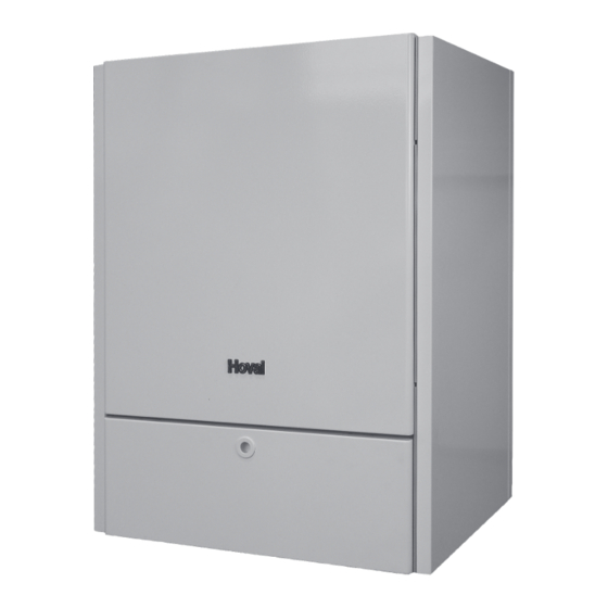
gas condensing boiler for natural and liquid gas
Hide thumbs
Also See for TopGas 80:
- Installation instructions manual (38 pages) ,
- Operating instructions manual (12 pages)
Table of Contents
Advertisement
Quick Links
EN
Technical Information
Installation Instructions
Gas condensing boiler
TopGas
(80)
®
for natural and liquid gas
Hoval gas boilers are only to be installed and
placed in operation by technicians; these instruc-
tions are therefore intended for the specialist.
Electrical installation work is only to be carried
out by an electrician.
Rated output levels at 40/30°C and
natural gas
2-TopGas
(80)
®
Wall-mounted gas boilers TopGas
ing to DIN 4702, DIN EN 483 and DIN EN 677
are suitable and approved as heat producers for
hot water heating systems with a permissible
flow temperature of up to 85°C). They are de-
signed for a flexibly reduced operation in heating
systems according.
4 207 803 / 01 - 11/09
17,3 - 80,0 kW
(80) accord-
®
Subject to modifications
Advertisement
Table of Contents

Related Manuals for Hoval TopGas 80


Summary of Contents for Hoval TopGas 80
-
Page 1: Installation Instructions
TopGas (80) ® for natural and liquid gas Hoval gas boilers are only to be installed and placed in operation by technicians; these instruc- tions are therefore intended for the specialist. Electrical installation work is only to be carried out by an electrician. -
Page 2: Table Of Contents
Boiler flow resistance ....................8 Short description of the automatic firing unit BIC 335 ..........8 Control of the boiler ....................9 Adjustable parameters ....................11 Installation ..................... 13 Description of the Hoval TopGas ................13 ® 3.1.1 Diaphragm expansion tank ..................13 3.1.2... - Page 3 Contents 4 207 803 / 01 Commissioning ..................... 22 Setting the control ..................... 22 Water quality ......................22 4.2.1 Heating water ......................23 4.2.2 Filling and replacement water ..................23 4.2.3 Filling up the system ....................24 Gas adjustment ......................24 4.3.1 Bleeding the gas pipeline ....................
-
Page 4: General Information
/ maintenance work. and cleaning agents. - Do not exceed the maximum operating pressure Hoval gas boilers are only to be installed by and temperature of the gas boiler (see identifica- approved specialists. No modifications are to tion plate). -
Page 5: Regulations, Official Approvals
The appliance is only to be transported and stored • M 7459, Gas appliances with gas-air compound only in its original packing. Interim storage of Hoval controller gas boilers is only to take place in weather protected •... -
Page 6: Technical Information
2. Technical Information 4 207 803 / 01 Technical Information Technical Data Type (80) • Nominal output 80/60 °C with natural gas 15,8 - 72,4 • Nominal output 40/30 °C with natural gas 17,3 - 80,0 • Nominal output 80/60 °C with propane gas 19,5 - 72,4 •... -
Page 7: Dimensions
2. Technical Information 4 207 803 / 01 Dimensions Measurements (mm) • Distance from the side 50 mm • Distance from the ceiling dependent on the utilised flue gas pipeline system • In the front 500 mm View from bottom View from top 1 Gas connection Rp ¾"... -
Page 8: Boiler Flow Resistance
2. Technical Information 4 207 803 / 01 Boiler flow resistance Boiler incl. con- nection kit Boiler only Flow rate [m Short description of the automatic firing unit BIC 335 The automatic firing unit operates both without con- - Interface to display troller (TTT/N) and also without room station (RS- - OpenTherm- interface (RS-OT, TTT/N) OT). -
Page 9: Control Of The Boiler
2. Technical Information 4 207 803 / 01 Control of the boiler Control elements on the boiler control panel / Basic control N4.1 Usually, no settings of the basic control have to be made by the user. All settings have been made by the installer or by the manufacturer. - Page 10 2. Technical Information 4 207 803 / 01 Function Meaning, Description It is possible to read monetary values Current flow temperature z.B. 45° from here (Heating water temperature) Current return temperature z.B. 40° Current temperature in water heater z.B. 60° Current outdoor temerature z.B.
-
Page 11: Adjustable Parameters
2. Technical Information 4 207 803 / 01 Adjustable parameters Parameter 7 (2AH) – Set point DHW charging temperature – Using this parameter the reference value for the DHW temperature can be set where there is no room con- trol unit or other regulatory device installed. If a reference value is transmitted via an OT bus, the latter (value via OT) will always override this parameter. - Page 12 2. Technical Information 4 207 803 / 01 Parameter 24 (2BN) – Pump after-run time (heating operation – During the time which can be set using this parameter the pump continues to run after a phase of heating demand. Parameter 25 (2BO) – Maximum fan speed in heating operation mode – This parameter is used to set the maximum permitted fan speed in % in heating operation mode.
-
Page 13: Installation
4 207 803 / 01 Installation Description of the Hoval TopGas 3.1.3 Gas fittings ® The heat exchanger of the Hoval TopGas (80) com- Honeywell VK4125V gas controller for the automatic ® prises a corrosion-resistant aluminum casting, through regulation of the gas/combustion air ratio, see sec- which the heating water flows in series-parallel fashion tion 4.3.4. -
Page 14: Topgas Component Designation
3. Installation 4 207 803 / 01 3.1.8 TopGas component designation ® Figure 3.1.8-1 1 Burner viewing window 2 Fan 3 Flue gas air inlet 4 Water pressure deflector 5 Flue gas temperature sensor 6 Flow temperature sensor 7 Return temperature sensor 8 Ignition/ionisation electrode 9 Heat exchanger 10 Gas fitting... -
Page 15: Boiler Installation Room
For suitable hydraulic connections, please note the 3.4.4 Minimum flow rate instructions in the Hoval project planning documen- During the burner operation a circulation pump must tation. always be in operation too. The minimum flow rate... -
Page 16: To Be Provided By Customer
3. Installation 4 207 803 / 01 3.4.5 To be provided by customer A pressure expansion tank adapted to heating system, water volume and static height. 3.4.6 Examples of hydraulic interconnection TopGas (80) with water heater and direct heating ® circuit TopTronic T RS-T... -
Page 17: Flue Gas Connection, Chimney And Condensate Pipeline
The use of specially approved flue gas pipelines, Your Hoval agent can supply a suitable and approved b) Use of damp-insensitive flues, approved for flue flue gas system for your TopGas ®... -
Page 18: Natural Ventilation Flue Example
3. Installation 4 207 803 / 01 • When installing the pipes in a shaft, spacer ele- 3.5.3 Natural ventilation flue example ments must be mounted every 2 m. For the vertical supporting of the chimney pipeline, the very bottom element must be permanently fixed (mounting rail or pipe clip). -
Page 19: Flue Gas System For Room Sealed Operation
3. Installation 4 207 803 / 01 3.5.4 Flue gas system for room sealed operation 3.5.5 Roof heating centre concentric flue (room sealed) combustion air Verbrennungsluft combustion air Verbrennungsluft if necessary an Falls erforderlich ist inspection-T-piece is ein Inspektions-T- to attach Stück einzusetzen if necessary an inspection-T-piece... -
Page 20: Wall Outlet
3. Installation 4 207 803 / 01 3.5.6 Wall outlet TopGas... -
Page 21: Connection Of Pipelines
3. Installation 4 207 803 / 01 3.5.7 Connection of pipelines On of the boiler installation the pipelines are connected The provisions of the relevant national regulations directly to the feed and the return connectors. Please (SVGW directives, ÖVGW directives, DVGW-TRGI note the designations for the pipeline connectors in 86-96, DIN 4750) as well as local regulations of gas section 2.2. -
Page 22: Electrical Connection (Mains) 230 V, 50 Hz
3.6.2 Electrical connection (mains) 230 V, 50 Hz Your Hoval agent will provide you with a detailed The boiler is wired ready for connection. It is fitted with description of the power outputs of this type of con- a connector cable of approx. -
Page 23: Heating Water
4.2.2 Filling and replacement water The European Standard EN 14868 and the Directive For a plant using Hoval boilers untreated drink ing wa- VDI 2035 must be observed. In par ticular, attention ter is generally best suited as fil ling and replacement must be paid to the following stipulations: water. -
Page 24: Filling Up The System
4.3.4 Gas fitting Example: maximum fill-up quantity (as in table 1) The Hoval TopGas is equipped with a Honeywell ® 1600 l, maximum fill-up and make-up water content pneumatic modulating multiple setting device. scope during lifetime 4800 l. -
Page 25: Setting The Gas Flow Rate
4. Commissioning 4 207 803 / 01 4.3.5 Setting the gas flow rate Heat load NB Setting value = Important basic information: Operation Calorific value H If the minimum connection pressure (section 4.3.3) (kW/m is too low (e.g. because of clogged gas filter, under- = NB x 1000 dimensioned gas supply), the boiler will not achieve... -
Page 26: Handing Over To The User
4. Commissioning / 5. Decommissioning 4 207 803 / 01 Changeover from natural gas H to natural gas L F) with boiler already connected: The changeover to a low caloric natural gas is simple. - open the gas valve Only a check or correction of the CO ) value at max. -
Page 27: Decommissioning
6. System maintenance and cleaning 4 207 803 / 01 Decommissioning The following steps are to be taken if the compact - Remove the burner plate and bat-wing burners heating controller is to be placed out of operation (Figure 6.4.2a+b) for several weeks: - Wet clean the heat exchanger (do not use steel wire brushes) (Fig. - Page 28 6. System maintenance and cleaning 4 207 803 / 01 Mounting opening Plug connections Gas screw connection Burner plate Bolting burner plate Figure 6.4.1 Figure 6.4.2a Figure 6.4.2b - Fan must be remove first (Figure 6.4.2a) - The cleaning cover below is for visual control only and must be closed during cleaning process (Figure 6.4.3).
-
Page 29: Faults
7. Faults 4 207 803 / 01 Faults If a fault occurs the boiler will be shut down immediately. There is a differentiation between blocking and locking. Blocking means that the boiler can restart itself when there is no more failure. After repairing locking fault it is necessary to press the Reset-key to confirm, so the boiler can start again. - Page 30 7. Faults 4 207 803 / 01 P 52 Flue gas temperature blocking If the limiting temperature (parameter 58 (2GC) is exceeded, a blocking occurs. See drawing 5. Instead of the flue gas temperature the boiler body is observed. Locking: E 01 Flow sensor short-circuit If the temperature is higher than 125°C the connected flow sensor seems as short-circuit and responds...
- Page 31 7. Faults 4 207 803 / 01 E 12 Fan speed out of the limits If the fan actual-speed is out of a range of the fan set-speed for more than 15 seconds, a locking is oc- cured. A maximum variation is 20 % of the set value. E 13 Parameter programming After loading of a parameter from the laptop to the automatic firing unit the boiler will be locked automati-...
-
Page 32: Automatic Firing Unit Bic 335-Parameter List
4 207 803 / 01 Adjustment on the BIC 335 may only be Automatic firing unit BIC 335-Parameter list executed by authorised Hoval after-sales service personnel. The following data-sheet is only for information for the Hoval after sales service personnel! Description DHW Operation P2AA flow temperature surplus (DHW) 1°C... - Page 33 8. Automatic firing unit BIC 335-Parameter list 4 207 803 / 01 P2EB fan decrement value 5(00) –1 P2EC maximum fan speed 60(00) 64(00) –1 P2ED fan speed – second phase of pre-ventilation 30(00) 32(00) –1 P2EE fan speed following false start 60(00) 64(00) –1...
- Page 34 Copy for plant user C O N F I R M A T I O N The user (owner) of the system herewith confirms that - he has received adequate instruction in the operating and maintenance of the installation, - received and taken note of the operating and maintenance instructions and, where applicable other documents concerning the heat generator and any further components.
Need help?
Do you have a question about the TopGas 80 and is the answer not in the manual?
Questions and answers