Table of Contents
Advertisement
Quick Links
Advertisement
Chapters
Table of Contents
Troubleshooting

Related Manuals for Mitsubishi Electric PUHY-M200YNW-A1


Summary of Contents for Mitsubishi Electric PUHY-M200YNW-A1
- Page 2 It may also be in violation of applicable laws. Doing so may result in electric shock, malfunction, or fire. MITSUBISHI ELECTRIC CORPORATION cannot be held responsible for malfunctions or accidents result- Do not touch the refrigerant pipes and re- ing from the use of the wrong type of refrigerant.
- Page 3 Periodically check the unit base for dam- Install, operate, and store the unit in a space age. with as much floor area as indicated in the figure at right, and be sure to take safety If the damage is left uncorrected, the unit will fall and measures.
- Page 4 [2] Transportation and Installation Transportation and Installation When lifting the unit, pass the slings through the four designated sling holes. Improper lifting will cause the unit to topple or fall, re- sulting in serious injury. Do not lift the unit with the PP bands that are Observe the restrictions on the maximum used on some products.
- Page 5 [4] Piping Work Piping Work Piping work shall be kept to a minimum. When installing or relocating the unit, do not allow air or any substance other than The pipes shall be protected from physical the specified refrigerant to enter the refrig- damage.
- Page 6 After the wiring work has been completed, measure the insulation resistance, and make sure that it reads at least 1 MΩ. Failure to do so may result in electric leakage, malfunc- tion, or fire. Relocation and Repairs Relocation and Repairs Only qualified personnel must relocate or Check for refrigerant leaks before service.
- Page 7 Place a wet towel on the service valves be- Do not use existing refrigerant piping. fore brazing the pipes to keep the tempera- The old refrigerant and refrigerant oil in the existing pip- ture of the valves from rising above 120ºC ing contain a large amount of chlorine, which will cause (248ºF).
-
Page 8: Table Of Contents
CONTENTS Chapter 1 Check Before Servicing Preparation for Piping Work........................1 Handling and Characteristics of Piping Materials, Refrigerant, and Refrigerant Oil ....... 3 Working with Refrigerant Piping......................14 Water piping............................19 Precautions for Wiring ......................... 22 Cautionary notes on installation environment and maintenance............ 24 Chapter 2 Restrictions System Configurations .......................... - Page 9 CONTENTS Chapter 7 Troubleshooting Using Error Codes Error Code and Preliminary Error Code Lists ..................1 Error Code Definitions and Solutions: Codes [0 - 999]............... 8 Error Code Definitions and Solutions: Codes [1000 - 1999]............. 10 Error Code Definitions and Solutions: Codes [2000 - 2999]............. 14 Error Code Definitions and Solutions: Codes [3000 - 3999].............
- Page 10 Chapter 1 Check Before Servicing Preparation for Piping Work ........................ 1 1-1-1 Read before Servicing ..........................1 1-1-2 Tool Preparation ............................. 2 Handling and Characteristics of Piping Materials, Refrigerant, and Refrigerant Oil...... 3 1-2-1 Piping Materials ............................3 1-2-2 Storage of Piping Materials........................4 1-2-3 Characteristics of the New and Conventional Refrigerants ..............
- Page 11 GB_BS_01_G...
-
Page 12: Preparation For Piping Work
[1-1 Preparation for Piping Work ] Preparation for Piping Work 1 Check Before Servicing 1-1-1 Read before Servicing 1. Check the type of refrigerant used in the system to be serviced. Refrigerant Type Multi air conditioner for building application CITY MULTI:R32 2. -
Page 13: Tool Preparation
[1-1 Preparation for Piping Work ] 1-1-2 Tool Preparation Prepare the following tools and materials necessary for installing and servicing the unit. Tools for use with R32 (Adaptability of tools that are for use with R410A, R22, or R407C) 1. To be used exclusively with R32 (not to be used if used with R410A, R22, or R407C) Tools/Materials Notes Gauge Manifold... -
Page 14: Handling And Characteristics Of Piping Materials, Refrigerant, And Refrigerant Oil
[1-2 Handling and Characteristics of Piping Materials, Refrigerant, and Refrigerant Oil ] Handling and Characteristics of Piping Materials, Refrigerant, and Refrigerant Oil 1-2-1 Piping Materials Do not use the existing piping! 1. Copper pipe materials O-material (Annealed) Soft copper pipes (annealed copper pipes). They can easily be bent with hands. 1/2H-material (Drawn) Hard copper pipes (straight pipes). -
Page 15: Storage Of Piping Materials
[1-2 Handling and Characteristics of Piping Materials, Refrigerant, and Refrigerant Oil ] 1-2-2 Storage of Piping Materials 1. Storage location Store the pipes to be used indoors. (Warehouse at site or owner's warehouse) If they are left outdoors, dust, dirt, or moisture may infiltrate and contaminate the pipe. 2. -
Page 16: Characteristics Of The New And Conventional Refrigerants
[1-2 Handling and Characteristics of Piping Materials, Refrigerant, and Refrigerant Oil ] 1-2-3 Characteristics of the New and Conventional Refrigerants 1. Chemical property The new refrigerant R32 is as low in toxicity and slightly flammable refrigerant. However, because the specific gravity of vapor refrigerant is greater than that of air, leaked refrigerant in a closed room will accumulate at the bottom of the room and may cause hypoxia. -
Page 17: Precautions For Handling Equipment Using R32
[1-2 Handling and Characteristics of Piping Materials, Refrigerant, and Refrigerant Oil ] 1-2-4 Precautions for handling equipment using R32 When handling the units that use R32 refrigerant, observe the following notes. (The notes are based on the precautions re- garding R32 refrigerant contained in IEC 60335-2-40.) 1. - Page 18 Where electrical components are being changed, they shall be fit for the purpose and to the correct specification. At all times the MITSUBISHI ELECTRIC's Installation Manual and Service Handbook shall be followed. If in doubt, consult the dealer's technical department for assistance.
- Page 19 5) Pump down refrigerant system, if possible. 6) Make sure that cylinder is situated on the scales before recovery takes place. 7) Start the recovery machine and operate in accordance with MITSUBISHI ELECTRIC's instructions. 8) Do not overfill cylinders. (No more than 80% volume liquid charge) 9) Do not exceed the maximum working pressure of the cylinder, even temporarily.
- Page 20 [1-2 Handling and Characteristics of Piping Materials, Refrigerant, and Refrigerant Oil ] 10. Appropriate refrigerant recovery method 1) When removing refrigerant from a system, either for repairing or decommissioning, it is recommended good practice that all refrigerants are removed safely. 2) When transferring refrigerant into cylinders, ensure that only appropriate refrigerant recovery cylinders are employed.
- Page 21 [1-2 Handling and Characteristics of Piping Materials, Refrigerant, and Refrigerant Oil ] Repair 1) Portable equipment shall be repaired outside or in a workshop specially equipped for servicing units with slightly flammable refrigerants. 2) Ensure sufficient ventilation at the repair place. 3) Be aware that malfunction of the equipment may be caused by refrigerant loss and a refrigerant leak is possible.
- Page 22 [1-2 Handling and Characteristics of Piping Materials, Refrigerant, and Refrigerant Oil ] 12. Installation restrictions for outdoor units Do not install the unit where combustible gas may leak. - If combustible gas accumulates around the unit, fire or explosion may result. •...
- Page 23 [1-2 Handling and Characteristics of Piping Materials, Refrigerant, and Refrigerant Oil ] C: Create an appropriate ventilation open area. Good Longitudinal direction Opening: • Must occupy 80% of the longitudinal side of a space. • Must have an opening ratio of Height of an opening ≥...
-
Page 24: Refrigerant Oil
[1-2 Handling and Characteristics of Piping Materials, Refrigerant, and Refrigerant Oil ] 1-2-5 Refrigerant Oil 1. Refrigerating machine oil in the HFC refrigerant system HFC type refrigerants use a refrigerating machine oil different from that used in the R22 system. Note that the ester oil used in the system has properties that are different from commercially available ester oil. -
Page 25: Working With Refrigerant Piping
[1-3 Working with Refrigerant Piping ] Working with Refrigerant Piping 1-3-1 Pipe Brazing No changes have been made in the brazing procedures. Perform brazing with special care to keep foreign objects (such as oxide scale, water, and dust) out of the refrigerant system. Example: Inside the brazed connection Use of no inert gas during brazing Use of inert gas during brazing... -
Page 26: Air Tightness Test
[1-3 Working with Refrigerant Piping ] 1-3-2 Air Tightness Test No changes have been made in the detection method. Note that a refrigerant leak detector for R22 will not detect an R32 leak. Halide torch R22 leakage detector 1. Items to be strictly observed Pressurize the equipment with nitrogen up to the design pressure (4.15MPa[601psi]), and then judge the equipment's air tight- ness, taking temperature variations into account. -
Page 27: Vacuum Drying
[1-3 Working with Refrigerant Piping ] 1-3-3 Vacuum Drying (Photo1) 15010H (Photo2) 14010 Recommended vacuum gauge: ROBINAIR 14010 Thermistor Vacuum Gauge 1. Vacuum pump with a reverse-flow check valve (Photo1) To prevent the vacuum pump oil from flowing into the refrigerant circuit during power OFF or power failure, use a vacuum pump with a reverse-flow check valve. - Page 28 [1-3 Working with Refrigerant Piping ] 7. Notes To evacuate air from the entire system Applying a vacuum through the check joints at the refrigerant service valve on the high and low pressure sides (BV1 and 2) is not enough to attain the desired vacuum pressure. Be sure to apply a vacuum through the check joints at the refrigerant service valve on the high and low pressure sides (BV1 and 2) and also through the check joints on the high and low pressure sides (CJ1 and 2).
-
Page 29: Refrigerant Charging
[1-3 Working with Refrigerant Piping ] 1-3-4 Refrigerant Charging Cylinder with a siphon Cylinder without a siphon Cylin- Cylin- Cylinder color R32 is light blue. Refrigerant charging in the liquid state Valve Valve liquid liquid 1. Reasons R32 is a single refrigerant with a boiling point of -52°C (-62°F) and can be handled in a similar manner as with other single refrigerants, such as R22. -
Page 30: Water Piping
[1-4 Water piping ] Water piping 1. Precautions for water piping Consider the following when installing a water piping system. (1) Design pressure of the water piping Use a water pipe that can withstand pressure of at least 0.8 MPa. (2) Water pipe type Use copper, plastic, steel, or stainless steel pipes for the water circuit. - Page 31 [1-4 Water piping ] 2. Notes on corrosion (1) Water quality It is important to check the water quality beforehand. See table below (Circulating water/Makeup Water Quality Standards). Lower mid-range Tendency temperature water system Recirculating Items water Make-up Scale- Corrosive [20<T<60°C] water forming...
- Page 32 [1-4 Water piping ] 3. Correction by antifreeze-liquid concentration In HYBRID CITY MULTI system, antifreeze-liquid should be used to prevent the system from freezing. Refer to the following graphs for the capacity correction by antifreeze-liquid. Refer to (1) for antifreeze-liquid concentration, (2) and (3) for capacity correction by antifreeze-liquid concentration.
-
Page 33: Precautions For Wiring
[1-5 Precautions for Wiring ] Precautions for Wiring Control boxes house high-voltage and high-temperature electrical parts. They may still remain energized or hot after the power is turned off. When opening or closing the front cover of the control box, keep out of contact with the internal parts. Before inspecting the inside of the control box, turn off the power, leave the unit turned off for at least 10 minutes, and check that the voltage across pins 1 and 5 of connector RYPN has dropped to 20 VDC or less. - Page 34 [1-5 Precautions for Wiring ] 2) Check the wires are securely fastened to the screw terminals. Screw the screws straight down so as not to damage the screw threads. Hold the two round terminals back to back to ensure that the screw will screw down straight. After tightening the screw, mark a line through the screw head, washer, and terminals with a permanent marker.
-
Page 35: Cautionary Notes On Installation Environment And Maintenance
[1-6 Cautionary notes on installation environment and maintenance ] Cautionary notes on installation environment and maintenance Salt-resistant unit is resistant to salt corrosion, but not salt-proof. Please note the following when installing and maintaining outdoor units in marine atmosphere. 1) Install the salt-resistant unit out of direct exposure to sea breeze, and minimize the exposure to salt water mist. 2) Avoid installing a sun shade over the outdoor unit, so that rain will wash away salt deposits off the unit. -
Page 36: Chapter 2 Restrictions
Chapter 2 Restrictions System Configurations......................... 1 Types and Maximum Allowable Length of Cables................2 Switch Settings ............................. 3 M-NET Address Settings ........................4 2-4-1 Address Settings List ..........................4 2-4-2 Outdoor Unit Power Jumper Connector Connection................5 2-4-3 Outdoor Unit Centralized Controller Switch Setting ................5 2-4-4 Room Temperature Detection Position Selection ................... - Page 37 GB_BS_02_E...
-
Page 38: System Configurations
[2-1 System Configurations ] System Configurations 2 Restrictions 1. Table of compatible indoor units The table below summarizes the types of indoor units that are compatible with different types of outdoor units. (1) Standard series Outdoor units Composing units Maximum total Maximum Types of connectable capacity of con-... -
Page 39: Types And Maximum Allowable Length Of Cables
[2-2 Types and Maximum Allowable Length of Cables ] Types and Maximum Allowable Length of Cables 1. Wiring work (1) Notes 1) Have all electrical work performed by an authorized electrician according to the local regulations and instructions in this man- ual. -
Page 40: Switch Settings
[2-3 Switch Settings ] 2) Remote controller wiring MA remote controller ME remote controller Type VCTF, VCTFK, CVV, CVS, VVR, VVF, VCT Shielded cables CVVS, CPEVS, and MVVS Number of 2-core cable 2-core cable cores Cable type 2 *3 0.3 to 1.25mm 2 *3 *5 0.3 to 1.25mm Cable size... -
Page 41: M-Net Address Settings
[2-4 M-NET Address Settings ] M-NET Address Settings 2-4-1 Address Settings List 1. M-NET Address settings (1) Address settings table The need for address settings and the range of address setting depend on the configuration of the system. Unit or controller Address setting Setting method Facto-... -
Page 42: Outdoor Unit Power Jumper Connector Connection
[2-4 M-NET Address Settings ] 2-4-2 Outdoor Unit Power Jumper Connector Connection There are limitations on the total number of units that are connectable to each refrigerant system. Refer to the DATABOOK for details. System configu- Connection to Power supply unit Group operation Power supply switch connector connection ration... -
Page 43: Start/Stop Control Of Indoor Units
[2-4 M-NET Address Settings ] 2-4-5 Start/Stop Control of Indoor Units Each indoor unit (or group of indoor units) can be controlled individually by setting SW 1-9 and 1-10. *4 *5 Setting (SW1) Operation of the indoor unit when the operation is resumed after the unit was Function stopped Power ON/OFF by... -
Page 44: Miscellaneous Settings
[2-4 M-NET Address Settings ] 2-4-6 Miscellaneous Settings Cooling-only setting for the indoor unit: Cooling only model (Factory setting: SW3-1 "OFF.") When using indoor unit as a cooling-only unit, set SW3-1 to ON. 2-4-7 Various Control Methods Using the Signal Input/Output Connector on Outdoor Unit (1) Various connection options Terminal... - Page 45 [2-4 M-NET Address Settings ] (1) CN51 (2) CN3S Outdoor unit External input Relay circuit adapter External input control board Distant control Relay circuit adapter 1 Outdoor unit board CN3S control board CN51 Preparations in the field Maximum cable Preparations length is 10m Maximum cable in the field...
-
Page 46: Demand Control Overview
[2-5 Demand Control Overview ] Demand Control Overview (1) General outline of control Demand control is performed by using the external signal input to the 1-2 and 1-3 pins of CN3D on the outdoor units (OC). Between 2 and 4 steps of demand control is possible by setting DIP SW6-8 on the outdoor units (OC). DipSW6-8 Demand control switch Input to CN3D *2... -
Page 47: System Connection Example
[2-6 System Connection Example ] System Connection Example Examples of typical system connection are shown below. Refer to the Installation Manual that came with each device or controller for details. (1) An example of a system to which an MA remote controller is connected System Address start up for in- Connection to the system controller... -
Page 48: Example System With An Ma Remote Controller
[2-7 Example System with an MA Remote Controller ] Example System with an MA Remote Controller 2-7-1 Single Refrigerant System (Automatic Indoor/Outdoor Address Startup) (1) Sample control wiring Interlock operation with the ventilation unit Leave the male Group Group connector on CN41 as it is. - Page 49 [2-7 Example System with an MA Remote Controller ] Group operation of indoor units (4) Wiring method To perform a group operation of indoor units (IC), daisy- 1) Indoor/outdoor transmission line chain terminals 1 and 2 on the terminal block (TB15) on all indoor units (IC) in the same group, and then connect Daisy-chain terminals M1 and M2 of the terminal block terminals 1 and 2 on the terminal block (TB15) on the in-...
-
Page 50: Single Refrigerant System With Two Or More Lossnay Units
[2-7 Example System with an MA Remote Controller ] 2-7-2 Single Refrigerant System with Two or More LOSSNAY Units (1) Sample control wiring Interlock operation with the ventilation unit Leave the male Group Group connector on CN41 as it is. SW5-1 OFF TB15 TB15... - Page 51 [2-7 Example System with an MA Remote Controller ] 4) LOSSNAY connection (4) Wiring method Connect terminals M1 and M2 on the terminal block 1) Indoor/outdoor transmission line (TB5) on the indoor unit (IC) to the appropriate terminals Same as 2-7-1 on the terminal block (TB5) on LOSSNAY (LC).
-
Page 52: Grouped Operation Of Units In Separate Refrigerant Circuits
[2-7 Example System with an MA Remote Controller ] 2-7-3 Grouped Operation of Units in Separate Refrigerant Circuits (1) Sample control wiring Interlock operation with the ventilation unit Move the male connector Group Group Group from CN41 to CN40. SW5-1 OFF TB15 TB15 TB15... - Page 53 [2-7 Example System with an MA Remote Controller ] Shielded cable connection (4) Wiring method Daisy-chain the S terminal on the terminal block (TB7) on 1) Indoor/outdoor transmission line the outdoor units (OC) with the shield wire of the shielded cable.
-
Page 54: System With A Connection Of System Controller To Centralized Control Transmission Line
[2-7 Example System with an MA Remote Controller ] 2-7-4 System with a Connection of System Controller to Centralized Control Transmission Line (1) Sample control wiring An example of a system in which a system controller is connected to the transmission cable for the centralized control system and the power is supplied from the outdoor unit Interlock operation with the ventilation unit... - Page 55 [2-7 Example System with an MA Remote Controller ] (OC) in different refrigerant circuits. Short-circuit the (4) Wiring method earth terminal ( ) and the S terminal on the terminal 1) Indoor/outdoor transmission line block (TB7) on the outdoor unit whose power jumper connector is mated with CN40.
-
Page 56: System With A Connection Of System Controller To Indoor-Outdoor Transmission Line
[2-7 Example System with an MA Remote Controller ] 2-7-5 System with a Connection of System Controller to Indoor-Outdoor Transmission Line (1) Sample control wiring Interlock operation with the ventilation unit Move the male connector from CN41 to CN40. SW5-1 OFF ON Group Group Group... - Page 57 [2-7 Example System with an MA Remote Controller ] Shielded cable connection (4) Wiring method Daisy-chain the S terminal on the terminal block (TB7) on 1) Indoor/outdoor transmission line the outdoor units (OC) with the shield wire of the shielded cable.
-
Page 58: Example System With An Me Remote Controller
[2-8 Example System with an ME Remote Controller ] Example System with an ME Remote Controller 2-8-1 System with a Connection of System Controller to Centralized Control Transmission Line (1) Sample control wiring Interlock operation with the ventilation unit Move the male connector from CN41 to CN40. - Page 59 [2-8 Example System with an ME Remote Controller ] When 2 remote controllers are connected to the sys- (4) Wiring method 1) Indoor/outdoor transmission line Refer to the section on Switch Setting. Performing a group operation (including the group Same as 2-7-1 operation of units in different refrigerant circuits).
-
Page 60: Example System With An Ma And An Me Remote Controller
[2-9 Example System with an MA and an ME Remote Controller ] Example System with an MA and an ME Remote Controller 2-9-1 System with a Connection of System Controller to Centralized Control Transmission Line (1) Sample control wiring Move the male connector from CN41 to CN40. - Page 61 [2-9 Example System with an MA and an ME Remote Controller ] Same as 2-7-1 (4) Wiring method Group operation of indoor units 1) Indoor/outdoor transmission line Same as 2-7-1 Same as 2-7-1 4) ME remote controller wiring Shielded cable connection Same as 2-8-1 Same as 2-7-1 When 2 remote controllers are connected to the sys-...
-
Page 62: 2-10 Restrictions On Refrigerant Pipes
[2-10 Restrictions on Refrigerant Pipes ] 2-10 Restrictions on Refrigerant Pipes 2-10-1 Restrictions on Refrigerant Pipe Length (1) (E)M200 - (E)M500YNW models (Connection to the hydro unit (including water piping)) Outdoor unit 1st branching Indoor unit Hydro unit Joint Header branching Refrigerant piping Water piping Unit: m Item Piping in the figure Max. -
Page 63: Restrictions On Refrigerant Pipe Size
[2-10 Restrictions on Refrigerant Pipes ] 2-10-2 Restrictions on Refrigerant Pipe Size (1) Diameter of the refrigerant pipe between the outdoor unit and the first branch (outdoor unit pipe size) Outdoor unit set name Liquid pipe size (mm) [inch] Gas pipe size (mm) [inch] (total capacity) 200 model ø9.52 [3/8"]... -
Page 64: Restrictions On Refrigerant Pipe And Water Pipe Size
[2-10 Restrictions on Refrigerant Pipes ] 2-10-3 Restrictions on Refrigerant Pipe and Water Pipe Size (1) Refrigerant pipe between outdoor unit and Hydro unit (Part A) 1) Hydro units connectable to outdoor units Standard models High-efficient models Hydro unit Hydro unit Unit model Model name Unit model... -
Page 65: Hydro Unit Connection Method
[2-10 Restrictions on Refrigerant Pipes ] (2) Water pipe between Hydro unit and indoor units 1) Hydro unit’s header pipe (Part A’) Hydro unit Model name Inlet pipe size Outlet pipe size CMH-WM250V-A 40A (housing joint) 40A (housing joint) Hydro unit side CMH-WM350V-A 40A (housing joint) 40A (housing joint) -
Page 66: Chapter 3 Major Components, Their Functions And Refrigerant Circuits
Chapter 3 Major Components, Their Functions and Refrigerant Circuits External Appearance and Refrigerant Circuit Components of Outdoor Unit........1 3-1-1 External Appearance of Outdoor Unit ..................... 1 3-1-2 Outdoor Unit Refrigerant Circuits......................4 Outdoor Unit Refrigerant Circuit Diagrams..................9 Functions of the Major Components of Outdoor Unit..............13 Functions of the Major Components of Indoor Unit................ - Page 67 GB_BS_03_E...
-
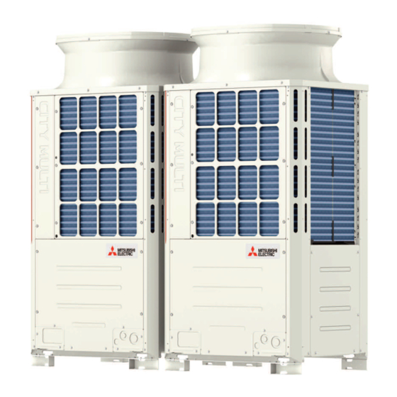
Page 68: External Appearance And Refrigerant Circuit Components Of Outdoor Unit
[3-1 External Appearance and Refrigerant Circuit Components of Outdoor Unit ] External Appearance and Refrigerant Circuit Components of 3 Major Components, Their Functions and Refrigerant Circuits Outdoor Unit 3-1-1 External Appearance of Outdoor Unit (1) PUHY-M200, M250, M300YNW-A1 PUHY-EM200, EM250, EM300YNW-A1 Fan guard Fan guard Front panel... - Page 69 [3-1 External Appearance and Refrigerant Circuit Components of Outdoor Unit ] (2) PUHY-M350, M400, M450YNW-A1 PUHY-EM350, EM400, EM450YNW-A1 Fan guard Fan guard Fin guard Fin guard Heat exchanger Heat exchanger Rear panel Rear panel Side panel Side panel Internal panel Internal panel Internal panel Internal panel...
- Page 70 [3-1 External Appearance and Refrigerant Circuit Components of Outdoor Unit ] (3) PUHY-M500YNW-A1 PUHY-EM500YNW-A1 Fan guard Fan guard Fin guard Fin guard Side panel Side panel Heat exchanger Heat exchanger Rear panel Rear panel Side panel Side panel Control box Control box Internal panel Internal panel...
-
Page 71: Outdoor Unit Refrigerant Circuits
[3-1 External Appearance and Refrigerant Circuit Components of Outdoor Unit ] 3-1-2 Outdoor Unit Refrigerant Circuits (1) PUHY-M200, M250, M300YNW-A1 Check valve (CV1) Solenoid valve (SV1a) Linear expansion valve (LEV1) Gas-liquid separator Low-pressure sensor (63LS) Subcool coil Accumulator Oil separator High-pressure sensor (63HS1) High-pressure switch... - Page 72 [3-1 External Appearance and Refrigerant Circuit Components of Outdoor Unit ] (2) PUHY-EM200, EM250, EM300YNW-A1 Check valve (CV1) Check valve (CV3) Solenoid valve (SV1a) Linear expansion valve (LEV1) Low-pressure sensor (63LS) Subcool coil Gas-liquid separator Accumulator Oil separator High-pressure sensor (63HS1) High-pressure High-pressure switch...
- Page 73 [3-1 External Appearance and Refrigerant Circuit Components of Outdoor Unit ] (3) PUHY-M350, M400, M450YNW-A1 Check valve (CV1) Linear expansion valve (LEV1) Gas-liquid separator Subcool coil Low-pressure sensor (63LS) Oil separator High-pressure sensor (63HS1) High-pressure check joint (CJ1) High-pressure switch (63H1) Accumulator Four-way valve (21S4a)
- Page 74 [3-1 External Appearance and Refrigerant Circuit Components of Outdoor Unit ] (4) PUHY-EM350, EM400, EM450YNW-A1 Check valve (CV1) Check valve (CV3) Linear expansion valve (LEV1) Gas-liquid separator Subcool coil Low-pressure sensor (63LS) Oil separator High-pressure check joint (CJ1) High-pressure sensor (63HS1) Accumulator High-pressure...
- Page 75 [3-1 External Appearance and Refrigerant Circuit Components of Outdoor Unit ] (5) PUHY-(E)M500YNW-A1 High-pressure sensor (63HS1) Four-way valve Linear expansion High-pressure switch (63H1) (21S4c) valve (LEV4) Four-way valve (21S4b) High-pressure check joint (CJ1) Four-way valve Check valve (CV1) (21S4a) Linear expansion Compressor valve (LEV1) Accumulator...
-
Page 76: Outdoor Unit Refrigerant Circuit Diagrams
[3-2 Outdoor Unit Refrigerant Circuit Diagrams ] Outdoor Unit Refrigerant Circuit Diagrams (1) PUHY-M200-M450YNW-A1 BS_03_E chapter 3 -... - Page 77 [3-2 Outdoor Unit Refrigerant Circuit Diagrams ] (2) PUHY-M500YNW-A1 - chapter 3 BS_03_E...
- Page 78 [3-2 Outdoor Unit Refrigerant Circuit Diagrams ] (3) PUHY-EM200-EM450YNW-A1 BS_03_E chapter 3 -...
- Page 79 [3-2 Outdoor Unit Refrigerant Circuit Diagrams ] (4) PUHY-EM500YNW-A1 - chapter 3 BS_03_E...
-
Page 80: Functions Of The Major Components Of Outdoor Unit
[3-3 Functions of the Major Components of Outdoor Unit ] Functions of the Major Components of Outdoor Unit Part Symbols Notes Usage Specifications Check method name (functions) Com- Adjusts the amount of circulating (E)M200 - (E)M350 models pressor (Comp1) refrigerant by adjusting the operat- Low-pressure shell scroll ing frequency based on the oper- compressor... - Page 81 [3-3 Functions of the Major Components of Outdoor Unit ] Part Symbols Notes Usage Specifications Check method name (functions) Thermis- 1) Detects discharge air temper- Degrees Celsius Resistance check (Discharge ature = 7.465k temperature) = 4057 2) Provides high-pressure pro- 25/120 tection 7.465...
- Page 82 [3-3 Functions of the Major Components of Outdoor Unit ] Part Symbols Notes Usage Specifications Check method name (functions) Sole- SV1a 1) High/low pressure bypass at AC220-240V Continuity check noid Discharge- Open while being powered/ with a tester start-up and stopping, and valve suction closed while not being pow-...
- Page 83 [3-3 Functions of the Major Components of Outdoor Unit ] Part Symbols Notes Usage Specifications Check method name (functions) FAN motor FAN mo- Regulates the heat exchanger ca- AC380-400V, 920W motor tor 2 is pacity by adjusting the operating *The (E)M200-300/500 mod- only on frequency and operating the pro- els and (E)M350-450 models...
-
Page 84: Functions Of The Major Components Of Indoor Unit
[3-4 Functions of the Major Components of Indoor Unit ] Functions of the Major Components of Indoor Unit Part Symbol Notes Usage Specification Check method Name (functions) Flow con- Controls the rate of water flow DC12V Refer to the section [8- trol valve to the indoor unit. -
Page 85: External Appearance And Refrigerant Circuit Components Of Hydro Unit
[3-5 External Appearance and Refrigerant Circuit Components of Hydro Unit ] External Appearance and Refrigerant Circuit Components of Hydro Unit 1. Front Refrigerant pipe (Liquid) Refrigerant pipe (Gas) 2. Rear To indoor units Water inlet From indoor units Exp. vessel - chapter 3 BS_03_E... - Page 86 [3-5 External Appearance and Refrigerant Circuit Components of Hydro Unit ] 3. Rear right side Control box Heat exchanger LEV1 Water pump BS_03_E chapter 3 -...
-
Page 87: Hydro Unit Refrigerant Circuit Diagrams
[3-6 Hydro Unit Refrigerant Circuit Diagrams ] Hydro Unit Refrigerant Circuit Diagrams - chapter 3 BS_03_E... -
Page 88: Functions Of The Major Components Of Hydro Unit
[3-7 Functions of the Major Components of Hydro Unit ] Functions of the Major Components of Hydro Unit Part name Symbols Notes Usage Specifications Check method Solenoid Refriger- Opens when the heat exchanger AC220-240V Continuity check valve ant side is not in operation (during freeze Open when energized/ with a tester protection, bypass defrost) - Page 89 [3-7 Functions of the Major Components of Hydro Unit ] - chapter 3 BS_03_E...
-
Page 90: Chapter 4 Electrical Components And Wiring Diagrams
Chapter 4 Electrical Components and Wiring Diagrams Outdoor Unit Circuit Board Arrangement................... 1 4-1-1 Outdoor Unit Control Box........................1 Outdoor Unit Circuit Board Components ................... 6 4-2-1 Control Board............................6 4-2-2 Power-supply board (PS Board) ......................7 4-2-3 Inverter Board (INV Board) ........................9 4-2-4 Fan Board ............................. - Page 91 GB_BS_04_E...
-
Page 92: Outdoor Unit Circuit Board Arrangement
[4-1 Outdoor Unit Circuit Board Arrangement ] Outdoor Unit Circuit Board Arrangement 4 Electrical Components and Wiring Diagrams 4-1-1 Outdoor Unit Control Box <HIGH VOLTAGE WARNING> Control box houses high-voltage parts. When opening or closing the front panel of the control box, do not let it come into contact with any of the internal components. - Page 93 [4-1 Outdoor Unit Circuit Board Arrangement ] MAIN BOX Control board PS board Transmission cable terminal block (TB3, TB7) Note 1) Note 1) Note 1) Connector RYPS1 (white 3pin) RYPS2 (white 5pin) RY63H (white 2pin) 1) Leave the grounding connected during maintenance. chapter 4 BS_04_E...
- Page 94 [4-1 Outdoor Unit Circuit Board Arrangement ] INV BOX Fan board Noise filter Power-supply terminal block INV board RYFAN1 PYPN (1 pin +, 5 pin -) *The figure at left shows the unit seen from the left after the front panel and the left side panel were removed.
- Page 95 [4-1 Outdoor Unit Circuit Board Arrangement ] (2) PUHY-(E)M350, (E)M400, (E)M450YNW-A1 Fan board (right) Noise filter Fan board (left) Control board Capacitor board Power-supply terminal block Capacitor board Connector RYPN (1 pin +, 5 pin -) INV board Transmission cable terminal DC reactor (DCL) Cooling fan block (TB3, TB7)
- Page 96 [4-1 Outdoor Unit Circuit Board Arrangement ] (3) PUHY-(E)M500YNW-A1 Noise filter Fan board (right) Fan board (left) *The figure at left shows the unit seen from the left after the front panel and the left side panel were removed. Control board Power-supply terminal block INV board Connector RYPN...
-
Page 97: Outdoor Unit Circuit Board Components
[4-2 Outdoor Unit Circuit Board Components ] Outdoor Unit Circuit Board Components 4-2-1 Control Board CNPS CN603 Cooling fan control signal output CN4/4A/4B/4C Abbreviated name 5 VDC output Inverter reset signal output Serial communication CN600 Power-supply of connector color signal output CN601 signal output 9 VDC input... -
Page 98: Power-Supply Board (Ps Board)
[4-2 Outdoor Unit Circuit Board Components ] 4-2-2 Power-supply board (PS Board) (1) PUHY-(E)M200, (E)M250, (E)M300YNW-A1 CN100 L2-N Voltage input Ground Ground Ground Ground CNFAN2 FAN2INV power-supply output 17 VDC output CNFAN1 FAN1INV power-supply output 17 VDC output CN303 63H pressure switch input/output CNINV COMPINV... - Page 99 [4-2 Outdoor Unit Circuit Board Components ] (2) PUHY-(E)M350, (E)M400, (E)M450, (E)M500YNW-A1 CN100 L2-N Voltage input Zero-cross output Ground Ground Ground CNFG5 Ground CN300 Booster COMP gate voltage output Ground CNDC MAIN power-supply output 9 VDC output 13 VDC output LED1 Indoor unit system power supply...
-
Page 100: Inverter Board (Inv Board)
[4-2 Outdoor Unit Circuit Board Components ] 4-2-3 Inverter Board (INV Board) (1) PUHY-(E)M200, (E)M250, (E)M300YNW-A1 C700, C701, C705, C706 Smoothing capacitor SC-L2 CN-P, CN-N Input (L2) Connects to connector RYPN SC-P1 SC-L3 DCL terminal Input (L3) CNRY 12 VDC (Power-supply board) SC-L1 SC-PL... - Page 101 [4-2 Outdoor Unit Circuit Board Components ] (2) PUHY-(E)M350, (E)M400, (E)M450YNW-A1 CN-P, CN-N Connects to connector RYPN IGBT (rear) SC-L1 Input (L1) SC-P DCL terminal SC-L2 SC-P1 Input (L2) DCL terminal SC-L3 Input (L3) CNRY 12 VDC GND (Power-supply board) SC-U Inverter output (U) SC-V...
- Page 102 [4-2 Outdoor Unit Circuit Board Components ] (3) PUHY-(E)M500YNW-A1 LED1 Serial communication signal CN-P, CN-N Lit: Inverter operation R127 Signal input Connects to Blinking: Inverter error Overcurrent GND (MAIN circuit board) connector RYPN LED4 detection CNCTIB Signal output Lit: Microcomputer is energized. resistor DC current sensor input GND (MAIN circuit board)
-
Page 103: Fan Board
[4-2 Outdoor Unit Circuit Board Components ] 4-2-4 Fan Board LED01 Lit: Inverter operation CNDCP Blinking: Inverter error LED04 Bus voltage input (N) Lit: Microcomputer in operation RSH03 Current detection resistor RSH02 Current detection resistor RSH01 Current detection resistor CN81 17 VDC input CNINV Inverter output... -
Page 104: Noise Filter
[4-2 Outdoor Unit Circuit Board Components ] 4-2-5 Noise Filter (1) PUHY-(E)M200, (E)M250, (E)M300, (E)M350, (E)M400, (E)M450YNW-A1 Surge absorber circuit Surge absorber circuit Open-phase detection circuit Open-phase detection circuit Ground F1, F2, F3, F4 Fuse 250 VAC 6.3 A TB13 Input (L3) TB12 Input (L2) - Page 105 [4-2 Outdoor Unit Circuit Board Components ] (2) PUHY-(E)M500YNW-A1 TB12 TB11 Input (L2) Input (L1) Ground TB14 Input (N) F1, F2, F3, F4 Fuse 250 VAC 6.3 A TB13 Input (L3) TB33 (L3) TB32 Surge absorber circuit (L2) Surge absorber circuit Open-phase detection circuit TB31 Open-phase detection circuit...
-
Page 106: Filter Board
[4-2 Outdoor Unit Circuit Board Components ] 4-2-6 Filter Board (1) PUHY-(E)M500YNW-A1 CN1B Input CN1A BS_04_E chapter 4 -... -
Page 107: Capacitor Board (Cap Board)
[4-2 Outdoor Unit Circuit Board Components ] 4-2-7 Capacitor Board (CAP Board) (1) PUHY-(E)M350, (E)M400, (E)M450YNW-A1 CN-CAP Connects to CAP05Y FT-P1C Connects to CAP05Y C1-C4 Smoothing capacitor 1) When opening or closing the front panel of the control box, do not let it come into contact with any of the internal components. Before inspecting the inside of the control box, turn off the power, keep the unit off for at least 10 minutes, and confirm that the capacitor voltage (inverter main circuit) has dropped to 20 VDC or less. -
Page 108: Outdoor Unit Electrical Wiring Diagrams
[4-3 Outdoor Unit Electrical Wiring Diagrams ] Outdoor Unit Electrical Wiring Diagrams (1) PUHY-(E)M200, (E)M250, (E)M300YNW-A1 BS_04_E chapter 4 -... - Page 109 [4-3 Outdoor Unit Electrical Wiring Diagrams ] (2) PUHY-(E)M350, (E)M400, (E)M450YNW-A1 18 - chapter 4 BS_04_E...
- Page 110 [4-3 Outdoor Unit Electrical Wiring Diagrams ] (3) PUHY-(E)M500YNW-A1 BS_04_E chapter 4 -...
-
Page 111: Transmission Booster Electrical Wiring Diagrams
[4-4 Transmission Booster Electrical Wiring Diagrams ] Transmission Booster Electrical Wiring Diagrams Terminal block for power supply (TB1) 250V 5A Red Red Red Black White White Green/Yellow 220 - 240VAC Varistor Noise filter Black White White White White Varistor Green Black Stabilized power supply Blue... -
Page 112: Hydro Unit Circuit Board Arrangement
[4-5 Hydro Unit Circuit Board Arrangement ] Hydro Unit Circuit Board Arrangement 4-5-1 Hydro Unit Control Box 1. CMH-WM250, 350, 500V-A Control board Transmission cable terminal block (TB3) RYPN (1pin+, 5pin-) Inverter board AC reactor (ACL) Power supply board Terminal block for power supply RYPN (1pin+, 5pin-) -
Page 113: Hydro Unit Circuit Board Components
[4-6 Hydro Unit Circuit Board Components ] Hydro Unit Circuit Board Components 4-6-1 Control Board SWP 01-03 CN991 SW 001, 002, 011 Dip switch Push switch Battery Box LD 001 Maintenance LED SWU 01, 02 Address Indoor-Outdoor transmission terminal block 22 - chapter 4 BS_04_E... -
Page 114: Power Supply Board (Ps Board)
[4-6 Hydro Unit Circuit Board Components ] 4-6-2 Power supply board (PS Board) LED 01 Lit: Microcomputer is energized Unlit: Microcomputer is not energized LED 02 Lit: Converter operation Blinking: Converter error FT 001, 002 ACL terminal F110 250VAC 6.3A T F111 250VAC 15A T... -
Page 115: Inverter Board (Inv Board)
[4-6 Hydro Unit Circuit Board Components ] 4-6-3 Inverter Board (INV Board) LED 4 Lit: Microcomputer is energized Unlit: Microcomputer is not energized LED 1 Lit: Inverter operation Unlit: Inverter error SC-R Input (L) SC-T Input (N) SC-U SC-W Inverter output (U) SC-V Inverter output (W) Inverter output (V) -
Page 116: Hydro Unit Electrical Wiring Diagrams
[4-7 Hydro Unit Electrical Wiring Diagrams ] Hydro Unit Electrical Wiring Diagrams (1) CMH-WM250, 350, 500V-A models BS_04_E chapter 4 -... - Page 117 [4-7 Hydro Unit Electrical Wiring Diagrams ] 26 - chapter 4 BS_04_E...
-
Page 118: Chapter 5 Control
Chapter 5 Control Dipswitch Functions and Factory Settings ..................1 5-1-1 Outdoor Unit Switch Functions and Factory Settings ................1 5-1-2 Indoor Unit Switch Functions and Factory Settings ................6 5-1-3 Remote Controller Switch Functions and Factory Settings..............7 5-1-4 Switch Functions <Hydro Unit>....................... - Page 119 GB_BS_05_E...
-
Page 120: Dipswitch Functions And Factory Settings
[5-1 Dipswitch Functions and Factory Settings ] Dipswitch Functions and Factory Settings 5 Control 5-1-1 Outdoor Unit Switch Functions and Factory Settings (1) Control board Function according to switch setting Switch Function Switch setting timing Unit address setting Set to 00 or 51-100 with the dial switch Before power on Without connection to With connection to the... - Page 121 [5-1 Dipswitch Functions and Factory Settings ] Function according to switch setting Switch Function Switch setting timing Enables or disables the detec- tion of the following types of inverter compressor errors ACCT, DCCT sensor error (5301 Detail code 115, 116) ACCT, DCCT sensor circuit Error detection dis- Error detection en-...
- Page 122 [5-1 Dipswitch Functions and Factory Settings ] 1) Unless otherwise specified, leave the switch to OFF where indicated by "-," which may be set to OFF for a reason. 2) When set to the performance-priority mode, the low-noise mode will be terminated, and the units will operate in the normal mode.
- Page 123 [5-1 Dipswitch Functions and Factory Settings ] (2) Additional dipswitch settings at time of shipment Function according to switch setting Switch Function Switch setting timing OFF (LED3 Unlit) ON (LED3 Lit) 1-10 Self-diagnosis/operation moni- SW6-10: Anytime after power on 1:ON, 0:OFF Sends a test-run signal No.769 1000000011...
- Page 124 [5-1 Dipswitch Functions and Factory Settings ] To change the settings, set SW6-10 to ON, set SW4, and press and hold SWP3 for 2 seconds or longer (OFF↔ON). LED3 will light up when the switch setting is ON, and lights off when OFF. Use the LED3 display to confirm that the settings are properly made.
-
Page 125: Indoor Unit Switch Functions And Factory Settings
[5-1 Dipswitch Functions and Factory Settings ] 5-1-2 Indoor Unit Switch Functions and Factory Settings (1) Dipswitches 1) SW1,3 Function according to switch setting Switch setting timing Switch Function Notes Room temperature Built-in sensor on Indoor unit inlet detection position the remote controller Not available Clogged filter detection... -
Page 126: Remote Controller Switch Functions And Factory Settings
[5-1 Dipswitch Functions and Factory Settings ] 2) SW2 Model Capacity (model) code setting Model W100 W125 Capacity (model) code setting The figure at left shows that the switches 1 through 5 are set to ON and 6 through 10 are set to OFF. 9 10 The setting timing for SW2 is before power is turned on. - Page 127 [5-1 Dipswitch Functions and Factory Settings ] (2) ME remote controller (PAR-F27MEA) Set the address of the remote controller with the rotary switch. Rotary switch 10's digit 1's digit (left) (right) Remote controller unit Example: In case of address 108 Address setting range Setting method Main remote controller...
-
Page 128: Switch Functions
[5-1 Dipswitch Functions and Factory Settings ] 5-1-4 Switch Functions <Hydro Unit> Function according to switch setting Switch setting tim- Switch Function Availability of freeze- Any time after be- Not available Available up protection heater ing energized SW001 Pressure sensor back- Error codes are sent to out- Error codes are not sent to Any time after be-... - Page 129 [5-1 Dipswitch Functions and Factory Settings ] Function according to switch setting Switch setting tim- Switch Function Opening of the flow control Water valve setting for Any time after be- According to the stop mode valve is fixed on all indoor water charge ing energized units.
-
Page 130: Outdoor Unit Control
[5-2 Outdoor Unit Control ] Outdoor Unit Control 5-2-1 Overview The outdoor units are designated as OC in the order of capacity from large to small (if two or more units have the same ca- pacity, in the order of address from small to large). The setting of outdoor unit can be verified by using the self-diagnosis switch (SW4). -
Page 131: Refrigerant Bypass Control
[5-2 Outdoor Unit Control ] 5-2-4 Refrigerant Bypass Control Bypass solenoid valves (SV1a), which bypass the high- and low- pressure sides, perform the following functions. (1) Bypass solenoid valve (SV1a) (ON = Open), (SV2) (ON = Open), (SV9) (ON = Open) SV1a Operation When starting-up the compressor of each... - Page 132 [5-2 Outdoor Unit Control ] SV10 Operation When Continuous heating (E)M200-450: Front part of heat exchang- Other than on the left mode er is being defrosted. *(E)M200-450: When the rear part of heat (E)M500: Front part of heat exchanger is exchanger is being defrosted, 21S4b will being defrosted.
-
Page 133: Frequency Control
[5-2 Outdoor Unit Control ] 5-2-5 Frequency Control Depending on the capacity required, the frequency of the compressor is controlled to keep constant evaporation temperature (0°C [32°F] = 0.71 MPa [103 psi]) during cooling operation, and condensing temperature (49°C [120°F] = 2.88 MPa [418 psi]) during heating operation. -
Page 134: Defrost Operation Control
[5-2 Outdoor Unit Control ] 5-2-6 Defrost Operation Control (1) Starting the defrost operation The defrost cycle will start when all of the three conditions (outside temperature, cumulative compressor operation time, and pipe temperature) under <Condition 1>, <Condition 2>, or <Condition 3> are met. Condition 1 Condition 2 Condition 3... - Page 135 [5-2 Outdoor Unit Control ] (2) Defrost operation Compressor frequency Model Compressor frequency Standard M200 model 100 Hz M250-300 models 100 Hz M350-400 models 121 Hz M450 model 147 Hz M500 model 147 Hz High COP EM200-300 models 100 Hz EM350 model 121 Hz EM400-450 models...
- Page 136 [5-2 Outdoor Unit Control ] (3) Stopping the defrost operation The defrost cycle ends when 12 minutes have passed since the beginning of the cycle, or when the pipe temperature (TH3) has been continuously detected for 4 minutes (when SW4 (916) is set to OFF) or 2 minutes (when SW4 (916) is set to ON) that exceeds the values in the table below.
-
Page 137: Continuous Heating Mode Control
[5-2 Outdoor Unit Control ] 5-2-7 Continuous heating mode control (1) Continuous heating mode start conditions Continuous heating mode will start when all the conditions listed in the table below are met (outside temperature, cumulative compressor operation time, and piping temperature). SW4 (848) must be set to ON to perform Continuous heating mode. -
Page 138: Refrigerant Recovery Control
[5-2 Outdoor Unit Control ] 5-2-8 Refrigerant Recovery Control Recovery of refrigerant is performed during cooling operation to prevent an excessive amount of refrigerant from accumulating in the outdoor heat exchanger. (1) During cooling operation Starting refrigerant recovery mode The refrigerant recovery mode starts when all the following conditions are met: 30 minutes have passed since the completion of previous refrigerant recovery. -
Page 139: Injection Control (Linear Expansion Valve
[5-2 Outdoor Unit Control ] 5-2-13 Injection Control (Linear Expansion Valve <LEV4>) LEV4 opening is adjusted every 30 seconds to keep the discharge temperature (TH4) within the predetermined range. 5-2-14 Control at Initial Startup When started up for the first time before 12 hours have elapsed after power on, the unit goes into the initial startup mode. At the completion of the initial operation mode on the OC, they will go into the normal control mode.) -
Page 140: Demand Control
[5-2 Outdoor Unit Control ] 5-2-16 Demand Control Cooling/heating operation can be prohibited (Thermo-OFF) by an external input to the indoor units. When DIP SW6-8 is set to ON, the 4-step DEMAND control is enabled. Eight-step demand control is possible in the system with two outdoor units. Twelve-step demand control is possible in the system with three outdoor units. -
Page 141: Hydro Unit Control
[5-3 Hydro Unit Control ] Hydro Unit Control 5-3-1 Water Pump Control Depending on the capacity required, temperature difference on the indoor units is controlled so as to be within a certain range. During normal operation, the changes in specified voltage of the water pump corresponding to the capacity of connectable indoor units are shown in the graph below. -
Page 142: Bypass Control
[5-3 Hydro Unit Control ] 5-3-2 Bypass Control Solenoid valve (SV1) that bypass the high- and low- pressure sides. It performs the following functions. (1) Bypass solenoid valve (SV1) (ON: open) Operation mode Cooling Thermo-ON Always OFF Heating Thermo-ON Always OFF Defrost Always OFF during heat recovery de- ON except to perform heat recovery... -
Page 143: Defrost Operation Control
[5-3 Hydro Unit Control ] 5-3-4 Defrost Operation Control (1) Defrost cycle type The defrost cycle has following two types: Bypass defrost that is the same method as that used in a CITY MULTI series sys- tem and heat recovery defrost (default) that the heat is collected from the water circuit and the defrost cycle ends early. The following figures shows the refrigerant flow for the bypass defrost and the heat recovery defrost. - Page 144 [5-3 Hydro Unit Control ] (2) Starting the defrost operation The defrost cycle will start when all of the three conditions (outside temperature, cumulative compressor operation time, and pipe temperature) under <Condition 1>, <Condition 2>, or <Condition 3> are met. Condition 1 Condition 2 Condition 3...
- Page 145 [5-3 Hydro Unit Control ] (4) Recovering from Defrost The setting of the dip switch 001-10 determines the defrost method (bypass defrost or heat recovery defrost). As shown in the following flow chart, the bypass defrost may be performed during the heat recovery defrost depending on the operation status.
-
Page 146: Refrigerant Recovery Control
[5-3 Hydro Unit Control ] 5-3-5 Refrigerant Recovery Control The refrigerant recovery control function controls the refrigerant flow at the Hydro unit during heating operation to keep the refrigerant from collecting inside the Hydro unit. It is also performed during cooling operation to prevent an excessive amount of refrigerant from accumulating in the outdoor heat exchanger. - Page 147 [5-3 Hydro Unit Control ] - chapter 5 BS_05_E...
-
Page 148: Chapter 6 Test Run
Chapter 6 Test Run Read before Test Run........................... 1 Operation Characteristics and Refrigerant Charge ................2 Evaluating and Adjusting Refrigerant Charge ................... 2 6-3-1 Refrigerant Overcharge and undercharge ....................2 6-3-2 Checking the Refrigerant Charge during Operation................2 6-3-3 Maximum refrigerant charge ........................3 6-3-4 Refrigerant Charge Adjustment Mode .................... - Page 149 GB_BS_06_E...
-
Page 150: Read Before Test Run
[6-1 Read before Test Run ] Read before Test Run 6 Test Run (1) Check for refrigerant leak and loose cables and connectors. (2) When opening or closing the front panel of the control box, do not let it come into contact with any of the internal components. -
Page 151: Operation Characteristics And Refrigerant Charge
[6-2 Operation Characteristics and Refrigerant Charge ] Operation Characteristics and Refrigerant Charge It is important to have a clear understanding of the characteristics of refrigerant and the operating characteristics of air conditioners before attempting to adjust the refrigerant amount in a given system. The following table shows items of particular importance. -
Page 152: Maximum Refrigerant Charge
[6-3 Evaluating and Adjusting Refrigerant Charge ] 6-3-3 Maximum refrigerant charge There is a limit to the amount of refrigerant that can be charged into a unit. Observe the maximum refrigerant charge in the table below. M200-500YNW-A1 Total index of the outdoor units M200 M250 M300... -
Page 153: Refrigerant Charge Adjustment Mode
[6-3 Evaluating and Adjusting Refrigerant Charge ] 6-3-4 Refrigerant Charge Adjustment Mode Follow the procedures below to add or extract refrigerant as necessary depending on the operation mode. When the function switch (SW4 (922)) on the main board on the outdoor unit is turned to ON, the unit goes into the refrigerant amount adjust mode, and operation <A>... - Page 154 [6-3 Evaluating and Adjusting Refrigerant Charge ] Start Turn on SW4 (922) on the OC. Put all indoor units in the test run mode and run the units in cooling mode. Has the initial start-up mode been completed? Has it been at least 30 minutes since start up? Gradually add refrigerant from...
-
Page 155: Calculation Of The Amount Of Additional Refrigerant
[6-3 Evaluating and Adjusting Refrigerant Charge ] 6-3-5 Calculation of the Amount of Additional Refrigerant The amount of refrigerant to be added depends on the size and the total length of the liquid piping. Calculate the amount of refrigerant to be charged according to the formula below. Round up the calculation result to the nearest 0.1 kg (0.1 oz). - Page 156 [6-3 Evaluating and Adjusting Refrigerant Charge ] (2) Units "ft" and "oz" <Formula> When the piping length from the outdoor unit to the farthest hydro unit is 10 m (32 ft) or shorter Amount of ø3/4 total length ø5/8 total length ø1/2 total length ø3/8 total length ø1/4 total length...
-
Page 157: The Following Symptoms Are Normal
[6-4 The Following Symptoms Are Normal ] The Following Symptoms Are Normal Remote controller Symptoms Cause display The indoor unit does not start "Cooling (heating)" The unit cannot perform a heating (cooling) operation when other indoor after starting cooling (heating) icon blinks on the units on the same refrigerant system, are performing a cooling (heating) operation. -
Page 158: Hydro Unit Replacement Instructions
[6-5 Hydro Unit Replacement Instructions ] Hydro Unit Replacement Instructions 6-5-1 Debris removal operation This operation removes the debris that may have been introduced during installation from the water circuit. Perform this operation after completion of water- and refrigerant-piping work, air tightness test, evacuation of refrigerant circuits, refrigerant charging, and electrical work. -
Page 159: The Air Vent Operation
[6-5 Hydro Unit Replacement Instructions ] 6-5-2 The air vent operation This operation removes the air that remains after water is supplied to the water circuit. Perform this operation after completion of water- and refrigerant-piping work, air tightness test, evacuation of refrigerant circuits, and refrigerant charging (and debris removal, if performed). - Page 160 Chapter 7 Troubleshooting Using Error Codes Error Code and Preliminary Error Code Lists ..................1 Error Code Definitions and Solutions: Codes [0 - 999] ..............8 7-2-1 Error Code [0403] ........................... 8 7-2-2 Error Code [0404] ........................... 9 Error Code Definitions and Solutions: Codes [1000 - 1999] ............10 7-3-1 Error Code [1102] ..........................
- Page 161 7-6-21 Error Code [4230] Detail Code 125....................... 41 7-6-22 Error Codes [4235, 4236] Detail Code 125................... 42 7-6-23 Error Code [4230] Detail Code 126....................... 42 7-6-24 Error Codes [4240, 4245, 4246]......................43 7-6-25 Error Codes [4250, 4255, 4256] Detail Code 101................. 44 7-6-26 Error Codes [4250, 4255, 4256] Detail Code 104.................
- Page 162 7-8-20 Error Code [6834] ..........................78 7-8-21 Error Code [6840] ..........................79 7-8-22 Error Code [6841] ..........................79 7-8-23 Error Code [6842] ..........................80 7-8-24 Error Code [6843] ..........................81 7-8-25 Error Code [6846] ..........................82 Error Code Definitions and Solutions: Codes [7000 - 7999] ............83 7-9-1 Error Code [7100] ..........................
- Page 163 GB_BS_07_E...
-
Page 164: Error Code And Preliminary Error Code Lists
[7-1 Error Code and Preliminary Error Code Lists ] Error Code and Preliminary Error Code Lists 7 Troubleshooting Using Error Codes Searched unit Error Prelimi- (prelim- Error nary inary) Error code definition Notes Code error detail code code 4300 4305 0403 Serial communication error/Panel communication error (page 8) - Page 165 [7-1 Error Code and Preliminary Error Code Lists ] Searched unit Error Prelimi- (prelim- Error nary inary) Error code definition Notes Code error detail code code Backup operation [108] Abnormal bus voltage drop (Software detection) (page 35) [109] Abnormal bus voltage rise (Software detection) (page 37) [110] BUS voltage error (Hardware detection)
- Page 166 [7-1 Error Code and Preliminary Error Code Lists ] Searched unit Error Prelimi- (prelim- Error nary inary) Error code definition Notes Code error detail code code Indoor unit gas-side pipe (page 50) temperature (TH23) OA processing unit gas- 5103 1205 Temperature sensor fault side pipe temperature (page 50)
- Page 167 [7-1 Error Code and Preliminary Error Code Lists ] Searched unit Error Prelimi- (prelim- Error nary inary) Error code definition Notes Code error detail code code Backup operation [115] ACCT sensor fault (page 56) [116] DCCT sensor fault (page 56) [117] ACCT sensor circuit fault (page 57)
- Page 168 [7-1 Error Code and Preliminary Error Code Lists ] Searched unit Error Prelimi- (prelim- Error nary inary) Error code definition Notes Code error detail code code 6842 Indoor-outdoor communication: Transmission error (page 80) 6843 A control communication start bit detection error (page 81) 6846 Start-up time over...
- Page 169 [7-1 Error Code and Preliminary Error Code Lists ] Outdoor unit The last digit in the check error codes in the 4000's and 5000's and two-digit detail codes indicate if the codes apply to com- pressor inverter on fan inverter. Example Code 4225 (detail code 108): Bus voltage drop in the fan inverter system Code 4230 : Heatsink overheat protection in the compressor inverter system...
- Page 170 [7-1 Error Code and Preliminary Error Code Lists ] Hydro unit Which errors in the 4000's range apply to the pump inverter or the power-supply board can be determined by the lowest digit of the two-digit detail code. Example 4300 (Detail 01) code→Serial communication error Pump-inverter 4308 (Detail 08) code→Serial communication error Power-supply board The last digit Inverter system...
-
Page 171: Error Code Definitions And Solutions: Codes [0 - 999]
[7-2 Error Code Definitions and Solutions: Codes [0 - 999] ] Error Code Definitions and Solutions: Codes [0 - 999] 7-2-1 Error Code [0403] 1. Error code definition Serial communication error 2. Error definition and error detection method Serial communication error between the control board and the INV board on the compressor, and between the control board and the Fan board Detail code 1: Between the control board and the INV board Detail code 5, 6: Between the control board and the Fan board... -
Page 172: Error Code [0404]
[7-2 Error Code Definitions and Solutions: Codes [0 - 999] ] Hydro unit (1) Faulty wiring Check the following wiring connections. 1) Between the control board and the inverter board (Detail code 1) Control board Inverter board Power-supply board CN17V CN305 CNRST 2) Between the control board and the power-supply board (Detail code 8) -
Page 173: Error Code Definitions And Solutions: Codes [1000 - 1999]
[7-3 Error Code Definitions and Solutions: Codes [1000 - 1999] ] Error Code Definitions and Solutions: Codes [1000 - 1999] 7-3-1 Error Code [1102] 1. Error code definition Discharge temperature fault 2. Error definition and error detection method 1) If the discharge temperature of 120 °C [248°F] or more is detected during the operation (the first detection), the outdoor unit stops once, turns to anti-restart mode for 3 minutes, and restarts after 3 minutes automatically. -
Page 174: Error Code [1301]
[7-3 Error Code Definitions and Solutions: Codes [1000 - 1999] ] 7-3-2 Error Code [1301] 1. Error code definition Low pressure fault 2. Error definition and error detection method When starting the compressor from Stop Mode for the first time if low pressure reads 0.098MPa [14psi] immediately before start-up, the operation immediately stops. -
Page 175: Error Code [1302] (During Operation)
[7-3 Error Code Definitions and Solutions: Codes [1000 - 1999] ] 7-3-3 Error Code [1302] (during operation) 1. Error code definition High pressure fault 1 (Outdoor unit) 2. Error definition and error detection method 1) If the pressure of 3.78MPa [548psi] or higher is detected by the pressure sensor during operation (the first detection), the out- door stops once, turns to antirestart mode for 3 minutes, and restarts after 3 minutes automatically. -
Page 176: Error Code [1302] (At Startup)
[7-3 Error Code Definitions and Solutions: Codes [1000 - 1999] ] (18) Open phase in the power-supply due to improper Refer to item (5) in section [6-1 Read before Test Run]. power-supply wiring 7-3-4 Error Code [1302] (at startup) 1. Error code definition High pressure fault 2 (Outdoor unit) 2. -
Page 177: Error Code Definitions And Solutions: Codes [2000 - 2999]
[7-4 Error Code Definitions and Solutions: Codes [2000 - 2999] ] Error Code Definitions and Solutions: Codes [2000 - 2999] 7-4-1 Error Code [2500] (Models with a drain sensor) 1. Error code definition Drain sensor submergence 2. Error definition and error detection method 1) If an immersion of the drain sensor in the water is detected while the unit is in any mode other than the Cool/Dry mode and when the drain pump goes from OFF to ON, this condition is considered preliminary water leakage. -
Page 178: Error Code [2500] (Models With A Float Switch)
[7-4 Error Code Definitions and Solutions: Codes [2000 - 2999] ] 7-4-2 Error Code [2500] (Models with a float switch) 1. Error code definition Drain sensor submergence 2. Error definition and error detection method 1) If an immersion of the float switch in the water is detected while the unit is in any mode other than the Cool/Dry mode and when the drain pump goes from OFF to ON, this condition is considered preliminary water leakage. -
Page 179: Error Code [2501] (Water Pump Fault)
[7-4 Error Code Definitions and Solutions: Codes [2000 - 2999] ] 7-4-3 Error Code [2501] (Water pump fault) 1. Error code definition Water pump fault 2. Error definition and error detection method When clogged water circuit or water leaks from the water circuit is detected, the water pump is stopped for protection. When the following statuses are detected, the pump will be stopped. -
Page 180: Error Code [2502] (Models With A Drain Sensor)
[7-4 Error Code Definitions and Solutions: Codes [2000 - 2999] ] 7-4-4 Error Code [2502] (Models with a drain sensor) 1. Error code definition Drain pump fault 2. Error definition and error detection method 1) Make the drain sensor thermistor self-heat by passing current through it. If the temperature rise is small, it is interpreted that the sensor is immersed in water. -
Page 181: Error Code [2502] (Models With A Float Switch)
[7-4 Error Code Definitions and Solutions: Codes [2000 - 2999] ] 7-4-5 Error Code [2502] (Models with a float switch) 1. Error code definition Drain pump fault 2. Error definition and error detection method 1) The immersion of sensor tip in water is detected by the ON/OFF signal from the float switch. Submergence of the sensor When it is detected that the float switch has been ON for 15 seconds, it is interpreted that the sensor tip is immersed in water. -
Page 182: Error Code [2503]
[7-4 Error Code Definitions and Solutions: Codes [2000 - 2999] ] 7-4-6 Error Code [2503] 1. Error code definition Drain sensor (Thd) fault 2. Error definition and error detection method If the open or short circuit of the thermistor has been detected for 30 seconds, this condition is considered to be a preliminary error, and the unit goes into the 3-minute restart delay mode. -
Page 183: Error Code [2512] (Control Valve Failure) (Indoor Unit)
[7-4 Error Code Definitions and Solutions: Codes [2000 - 2999] ] 7-4-7 Error Code [2512] (Control valve failure) (Indoor unit) 1. Error code definition Flow control valve fault (indoor unit) 2. Error definition and error detection method Limit signal that is output from flow control valve is not detected or is not reset after it is detected. 3. -
Page 184: Error Code [2520]
[7-4 Error Code Definitions and Solutions: Codes [2000 - 2999] ] 7-4-9 Error Code [2520] 1. Error code definition Abnormal water pressure rise 2. Error definition and error detection method 1) If any of the following is detected for the first time during operation, the water pump turns to antirestart mode for 3 minutes, and automatically restarts after 3 minutes: Indoor unit water pressure of 950 kPa [138 psi] or higher Hydro unit PWD of 650 kPa [94 psi] or higher... -
Page 185: Error Code [2601]
[7-4 Error Code Definitions and Solutions: Codes [2000 - 2999] ] 7-4-10 Error Code [2600] 1. Error code definition Water leakage 2. Cause, check method and remedy Check that water does not leak from the pipes in such as the humidifier. 7-4-11 Error Code [2601] 1. -
Page 186: Error Code Definitions And Solutions: Codes [3000 - 3999]
[7-5 Error Code Definitions and Solutions: Codes [3000 - 3999] ] Error Code Definitions and Solutions: Codes [3000 - 3999] 7-5-1 Error Code [3121] 1. Error code definition Out-of-range outside air temperature 2. Error definition and error detection method When the thermistor temperature of -28°C[-18°F] or below has continuously been detected for 3 minutes during heating op- eration (during compressor operation), the unit makes an error stop and "3121"... -
Page 187: Error Code [3511]
[7-5 Error Code Definitions and Solutions: Codes [3000 - 3999] ] 7-5-2 Error Code [3511] 1. Error code definition Refrigerant overcooling 2. Error definition and error detection method 1) If the condition "THHS ≤ A °C remains true for continuous 6 minutes and 30 seconds" is met (for the first time) during oper- ation, the outdoor unit will stop, go into the three-minute restart delay mode, and then automatically resume operation after three minutes have passed. - Page 188 [7-5 Error Code Definitions and Solutions: Codes [3000 - 3999] ] 7-5-3 Error Code [3512] 1. Error code definition Cooling fan locking 2. Error definition and error detection method The motor on the cooling fan locks during operation. 3. Cause, check method and remedy Cause Check method and remedy Locked cooling fan motor...
-
Page 189: Error Code Definitions And Solutions: Codes [4000 - 4999]
[7-6 Error Code Definitions and Solutions: Codes [4000 - 4999] ] Error Code Definitions and Solutions: Codes [4000 - 4999] 7-6-1 Error Code [4102] 1. Error code definition Open phase 2. Error definition and error detection method An open phase of the power supply (L1 phase, N phase) was detected at power on. The L3 phase current is outside of the specified range. -
Page 190: Error Code [4106]
[7-6 Error Code Definitions and Solutions: Codes [4000 - 4999] ] 7-6-2 Error Code [4106] 1. Error code definition <Transmission power supply fault Error detail code FF (Outdoor unit)> 2. Error definition and error detection method Transmission power output failure 3. -
Page 191: Error Code [4121]
[7-6 Error Code Definitions and Solutions: Codes [4000 - 4999] ] 7-6-4 Error Code [4114] 1. Error code definition Indoor unit fan motor error 2. Error definition and error detection method When the fan motor output from the indoor unit circuit board is ON and when the rotation speed input from the fan motor cannot be detected for 30 seconds or more 3. -
Page 192: Error Code [4129] Detail Code 101
[7-6 Error Code Definitions and Solutions: Codes [4000 - 4999] ] 7-6-5 Error Code [4115] Detail Code 101, 102 1. Error code definition Power supply signal sync error 2. Error definition and error detection method The frequency cannot be determined when the power is switched on. 3. -
Page 193: Error Code [4130]
[7-6 Error Code Definitions and Solutions: Codes [4000 - 4999] ] 7-6-6 Error Code [4116] 1. Error code definition RPM error/Motor error 2. Error definition and error detection method LOSSNAY The motor keep running even if the power is OFF. The thermal overload relay is ON. - Page 194 [7-6 Error Code Definitions and Solutions: Codes [4000 - 4999] ] 7-6-8 Error Code [4124] 1. Error code definition Electric system not operate due to damper abnormality 2. Error definition and error detection method When the damper is not located at the designated position. 3.
- Page 195 [7-6 Error Code Definitions and Solutions: Codes [4000 - 4999] ] 7-6-9 Error Code [4129] Detail Code 101 1. Error code definition Converter error (Detail code 101) 2. Error definition and error detection method Vdc ≥ 420 V or an overcurrent through the converter was detected during inverter operation. 3.
- Page 196 [7-6 Error Code Definitions and Solutions: Codes [4000 - 4999] ] 7-6-11 Error Code [4130] 1. Error code definition Control power supply error 2. Error definition and error detection method No power is supplied to the control board from the power board. 3.
- Page 197 [7-6 Error Code Definitions and Solutions: Codes [4000 - 4999] ] 7-6-12 Error Code [4131] 1. Error code definition Slightly open indoor unit valve during power cut 2. Error definition and error detection method On the indoor units to which no power is supplied, when a temperature difference of 10°C or greater is detected between the return air temperature (TH1) and the inlet water temperature (TH2) continuously for 5 minutes during cooling operation, the error code [4131] will be displayed, and the system will come to an abnormal stop.
- Page 198 [7-6 Error Code Definitions and Solutions: Codes [4000 - 4999] ] 7-6-13 Error Codes [4220, 4225, 4226] Detail Code 108 1. Error code definition Abnormal bus voltage drop (Detail code 108) 2. Error definition and error detection method If Vdc 289V or less is detected during Inverter operation. (S/W detection) (Outdoor unit) If Vdc 150V or less is detected during Inverter operation.
- Page 199 [7-6 Error Code Definitions and Solutions: Codes [4000 - 4999] ] Hydro unit (1) Power supply environment Find out if there was a (momentary) power failure. Check that the power-supply voltage between L and N is 198 V or greater. Check the power supply voltage waveform for distortion.
- Page 200 [7-6 Error Code Definitions and Solutions: Codes [4000 - 4999] ] 7-6-14 Error Codes [4220, 4225, 4226] Detail Code 109 1. Error code definition Abnormal bus voltage rise (Detail code 109) 2. Error definition and error detection method If Vdc 830V is detected during inverter operation.
- Page 201 [7-6 Error Code Definitions and Solutions: Codes [4000 - 4999] ] 7-6-16 Error Codes [4220, 4225, 4226] Detail Code 111, 112 1. Error code definition Logic error (Detail code 111, 112) 2. Error definition and error detection method Hardware error If only the hardware error logic circuit operates, and no identifiable error is detected.
- Page 202 [7-6 Error Code Definitions and Solutions: Codes [4000 - 4999] ] 7-6-18 Error Code [4220] Detail Code 129 1. Error code definition Control power supply error (Detail code 129)(outdoor unit) 2. Error definition and error detection method INV35Y and INV42Y Detection of insufficient drive voltage for relays on INV board INV37YC Detection of insufficient drive voltage for relays on INV board or for IGBT...
- Page 203 [7-6 Error Code Definitions and Solutions: Codes [4000 - 4999] ] 7-6-20 Error Code [4228] Detail Code 101 1. Error code definition BUS voltage error (Software detection) 2. Error definition and error detection method "Vdc ≥ 425V" or "Vdc≤150V" was detected during inverter operation. 3.
- Page 204 [7-6 Error Code Definitions and Solutions: Codes [4000 - 4999] ] 7-6-21 Error Code [4230] Detail Code 125 1. Error code definition Heatsink overheat protection (Detail code 125) 2. Error definition and error detection method Outdoor unit When the heat sink temperature (THHS) remains at or above TOH is detected. models INV35Y, 42Y 100°C...
- Page 205 [7-6 Error Code Definitions and Solutions: Codes [4000 - 4999] ] 7-6-22 Error Codes [4235, 4236] Detail Code 125 1. Error code definition Heatsink overheat protection (Detail code 125) (outdoor unit) 2. Error definition and error detection method Detection of fan INV heatsink temperature (THHS) ≥ 100°C 3.
-
Page 206: Error Codes [4240, 4245, 4246]
[7-6 Error Code Definitions and Solutions: Codes [4000 - 4999] ] 7-6-24 Error Codes [4240, 4245, 4246] 1. Error code definition Overload protection 2. Error definition and error detection method If the output current of "(Iac) >Imax (Arms)" or "THHS > TOL" is continuously detected for 10 minutes during inverter operation. Refer to the following page(s). - Page 207 [7-6 Error Code Definitions and Solutions: Codes [4000 - 4999] ] 7-6-25 Error Codes [4250, 4255, 4256] Detail Code 101 1. Error code definition IPM error (Detail code 101) 2. Error definition and error detection method In the case of 4250 If an overcurrent is detected by the overcurrent detection circuit CT003 (R127 when INV37YC) on the INV board.
- Page 208 [7-6 Error Code Definitions and Solutions: Codes [4000 - 4999] ] 7-6-26 Error Codes [4250, 4255, 4256] Detail Code 104 1. Error code definition Short-circuited IPM/Ground fault (Detail code 104) 2. Error definition and error detection method When IPM/IGBT short damage or grounding on the load side is detected just before starting the inverter. 3.
- Page 209 [7-6 Error Code Definitions and Solutions: Codes [4000 - 4999] ] 7-6-27 Error Codes [4250, 4255, 4256] Detail Code 105 1. Error code definition Overcurrent error due to short-circuited motor (Detail code 105) 2. Error definition and error detection method When a short is detected on the load side just before starting the inverter operation.
-
Page 210: Error Codes [4250, 4255, 4256] Detail Codes 106 And 107
[7-6 Error Code Definitions and Solutions: Codes [4000 - 4999] ] 7-6-28 Error Codes [4250, 4255, 4256] Detail Codes 106 and 107 1. Error code definition Instantaneous overcurrent breaker error (Detail code 106) Overcurrent breaker error (effective value) (Detail code 107) 2. - Page 211 [7-6 Error Code Definitions and Solutions: Codes [4000 - 4999] ] 7-6-29 Error Code [4250] Detail Codes 121, 128, and 122 1. Error code definition DCL overcurrent error (H/W) (Detail code 121 and 128)(outdoor unit) DCL overcurrent error (S/W) (Detail code 122) (outdoor unit) 2.
-
Page 212: Error Code [4260]
[7-6 Error Code Definitions and Solutions: Codes [4000 - 4999] ] 7-6-31 Error Code [4260] 1. Error code definition Heatsink overheat protection at startup 2. Error definition and error detection method Outdoor unit When heatsink temperature (THHS) remains at or above TOH for 10 minutes or longer after inverter startup models INV35Y, 42Y 100˚C... -
Page 213: Error Code Definitions And Solutions: Codes [5000 - 5999]
[7-7 Error Code Definitions and Solutions: Codes [5000 - 5999] ] Error Code Definitions and Solutions: Codes [5000 - 5999] 7-7-1 Error Codes [5101, 5102, 5103, 5104] 1. Error code definition 5101 Return air temperature sensor (TH21) fault (Indoor unit) Return air temperature sensor (TH4) fault (OA processing unit) 5102 Pipe temperature sensor (TH22) fault (Indoor unit) -
Page 214: Error Codes [5102,5103,5104,5105,5106,5107,5115]
[7-7 Error Code Definitions and Solutions: Codes [5000 - 5999] ] 7-7-2 Error Codes [5102,5103,5104,5105,5106,5107,5115] 1. Error code definition 5102 HIC bypass circuit outlet temperature sensor (TH2) fault (Outdoor unit) 5103 Heat exchanger outlet temperature sensor (TH3) fault (Outdoor unit) 5104 Discharge temperature sensor (TH4) fault (Outdoor unit) 5105... -
Page 215: Error Code [5110]
[7-7 Error Code Definitions and Solutions: Codes [5000 - 5999] ] 3. Cause, check method and remedy Cause Check method and remedy Thermistor failure Check thermistor resistance. Pinched lead wire Check for pinched lead wire. Torn wire coating Check for wire coating. A pin on the male connector is missing or Check connector. -
Page 216: Error Code [5111, 5113, 5132, 5135]
[7-7 Error Code Definitions and Solutions: Codes [5000 - 5999] ] 7-7-4 Error Code [5111, 5113, 5132, 5135] 1. Error code definition 5111 - 5113 Temperature sensor fault (Hydro unit) (TH11, TH13) 5132 - 5135 Temperature sensor fault (Hydro unit) (TH32, TH35) 2. -
Page 217: Error Code [5201]
[7-7 Error Code Definitions and Solutions: Codes [5000 - 5999] ] 7-7-6 Error Code [5201] 1. Error code definition 5201 Refrigerant pressure sensor fault (Outdoor unit 63HS1/Hydro unit Prf) 2. Error definition and error detection method When a pressure sensor reading of 4.06 MPa [589 psi] or above is detected, error code "5201" will appear. The unit will continue its operation by using other sensors as a backup. -
Page 218: Error Code [5202, 5203]
[7-7 Error Code Definitions and Solutions: Codes [5000 - 5999] ] 7-7-8 Error Code [5202] 1. Error code definition 5202 Water pressure sensor fault (indoor unit) 2. Error definition and error detection method When a pressure sensor reading of 1.05 MPa [153 psi] or above OR -0.05 MPa [7.3 psi] or below is detected, error code "5202"... - Page 219 [7-7 Error Code Definitions and Solutions: Codes [5000 - 5999] ] 7-7-10 Error Code [5301] Detail Code 115 1. Error code definition ACCT sensor fault (Detail code 115) 2. Error definition and error detection method When the formula "output current < 1.8 Arms" remains satisfied for 10 seconds while the inverter is in operation. When the formula "output current <...
- Page 220 [7-7 Error Code Definitions and Solutions: Codes [5000 - 5999] ] 7-7-11 Error Code [5301] Detail Code 117 1. Error code definition ACCT sensor circuit fault (Detail code 117) 2. Error definition and error detection method When an error value is detected with the ACCT detection circuit just before the inverter starts 3.
- Page 221 [7-7 Error Code Definitions and Solutions: Codes [5000 - 5999] ] 7-7-12 Error Code [5301] Detail Code 119 1. Error code definition Open-circuited IPM/Loose ACCT connector (Detail code 119) 2. Error definition and error detection method Presence of enough current cannot be detected during the self-diagnostic operation immediately before inverter startup. 3.
- Page 222 [7-7 Error Code Definitions and Solutions: Codes [5000 - 5999] ] 7-7-13 Error Code [5301] Detail Code 120 1. Error code definition Faulty ACCT wiring (Detail code 120) 2. Error definition and error detection method Presence of target current cannot be detected during the self-diagnostic operation immediately before startup. 3.
-
Page 223: Error Code [5701]
[7-7 Error Code Definitions and Solutions: Codes [5000 - 5999] ] 7-7-15 Error Codes [5305, 5306] Detail Code 135 1. Error code definition Current sensor fault (Detail code 135) 2. Error definition and error detection method Detection of output current below 0.2 Arms for 10 continuous seconds while fan motor is in operation 3. -
Page 224: Error Code Definitions And Solutions: Codes [6000 - 6999]
[7-8 Error Code Definitions and Solutions: Codes [6000 - 6999] ] Error Code Definitions and Solutions: Codes [6000 - 6999] 7-8-1 Error Code [6201] 1. Error code definition Remote controller board fault (nonvolatile memory error) 2. Error definition and error detection method This error is detected when the data cannot be read out from the built-in nonvolatile memory on the remote controller. -
Page 225: Error Code [6600]
[7-8 Error Code Definitions and Solutions: Codes [6000 - 6999] ] 7-8-3 Error Code [6600] 1. Error code definition Address overlap 2. Error definition and error detection method An error in which signals from more than one indoor units with the same address are received Detail code 001: Detection of overlapped address in centralized control system Detail code 002: Detection of overlapped address in indoor unit system The address and attribute that appear on the remote controller indicate the controller that detected the error. -
Page 226: Error Code [6606]
[7-8 Error Code Definitions and Solutions: Codes [6000 - 6999] ] 7-8-5 Error Code [6602] 1. Error code definition Transmission processor hardware error 2. Error definition and error detection method Although "0" was surely transmitted by the transmission processor, "1" is displayed on the transmission line. Detail code 001: Transmission processor hardware error in centralized control system Detail code 002: Transmission processor hardware error in indoor unit system The address/attribute appeared on the display on the remote controller indicates the controller where an error oc-... - Page 227 [7-8 Error Code Definitions and Solutions: Codes [6000 - 6999] ] 7-8-6 Error Code [6603] 1. Error code definition Transmission line bus busy error 2. Error definition and error detection method Generated error when the command cannot be transmitted for 4-10 minutes in a row due to bus-busy Generated error when the command cannot be transmitted to the transmission line for 4-10 minutes in a row due to noise Detail code 001: Transmission Bus-Busy error in centralized control system Detail code 002: Transmission Bus-Busy error in indoor unit system...
-
Page 228: Error Code [6607] Error Source Address = Outdoor Unit (Oc)
[7-8 Error Code Definitions and Solutions: Codes [6000 - 6999] ] 7-8-8 Error Code [6607] Error Source Address = Outdoor Unit (OC) 1. Error code definition No ACK error 2. Error definition and error detection method The error is detected when no acknowledgement (ACK signal) is received after the transmission. (eg. When the data is trans- mitted six times in a row with 30 seconds interval, the error is detected on the transmission side.) The address/attribute appeared on the display on the remote controller indicates the controller which did not provide the response (ACK). -
Page 229: Error Code [6607] Error Source Address = Indoor Unit (Ic)
[7-8 Error Code Definitions and Solutions: Codes [6000 - 6999] ] 7-8-9 Error Code [6607] Error Source Address = Indoor Unit (IC) 1. Error code definition No ACK error 2. Error definition and error detection method The error is detected when no acknowledgement (ACK signal) is received after the transmission. (eg. When the data is trans- mitted six times in a row with 30 seconds interval, the error is detected on the transmission side.) The address/attribute appeared on the display on the remote controller indicates the controller which did not provide the response (ACK). - Page 230 [7-8 Error Code Definitions and Solutions: Codes [6000 - 6999] ] (2) Troubleshooting problems for indoor units (B) Cause Check method and remedy When the power supply unit for transmission lines is used Check voltage of the transmission line for central- and the male power supply connector is connected to the ized control.
-
Page 231: Error Code [6607] Error Source Address = Hydro Unit (Hu)
[7-8 Error Code Definitions and Solutions: Codes [6000 - 6999] ] 7-8-10 Error Code [6607] Error Source Address = Hydro unit (HU) 1. Error code definition No ACK error 2. Error definition and error detection method The error is detected when no acknowledgement (ACK signal) is received after the transmission. (eg. When the data is trans- mitted six times in a row with 30 seconds interval, the error is detected on the transmission side.) The address/attribute appeared on the display on the remote controller indicates the controller which did not provide the response (ACK). -
Page 232: Error Code [6607] Error Source Address = Lossnay (Lc)
[7-8 Error Code Definitions and Solutions: Codes [6000 - 6999] ] 7-8-11 Error Code [6607] Error Source Address = LOSSNAY (LC) 1. Error code definition No ACK error 2. Error definition and error detection method The error is detected when no acknowledgement (ACK signal) is received after the transmission. (eg. When the data is trans- mitted six times in a row with 30 seconds interval, the error is detected on the transmission side.) The address/attribute appeared on the display on the remote controller indicates the controller which did not provide the response (ACK). -
Page 233: Error Code [6607] Error Source Address = Me Remote Controller
[7-8 Error Code Definitions and Solutions: Codes [6000 - 6999] ] 7-8-12 Error Code [6607] Error Source Address = ME Remote Controller 1. Error code definition No ACK error 2. Error definition and error detection method The error is detected when no acknowledgement (ACK signal) is received after the transmission. (eg. When the data is trans- mitted six times in a row with 30 seconds interval, the error is detected on the transmission side.) The address/attribute appeared on the display on the remote controller indicates the controller which did not provide the response (ACK). -
Page 234: Error Code [6607] Error Source Address = System Controller
[7-8 Error Code Definitions and Solutions: Codes [6000 - 6999] ] 7-8-13 Error Code [6607] Error Source Address = System Controller 1. Error code definition No ACK error 2. Error definition and error detection method The error is detected when no acknowledgement (ACK signal) is received after the transmission. (eg. When the data is trans- mitted six times in a row with 30 seconds interval, the error is detected on the transmission side.) The address/attribute appeared on the display on the remote controller indicates the controller which did not provide the response (ACK). -
Page 235: Error Code [6607] All Error Source Addresses
[7-8 Error Code Definitions and Solutions: Codes [6000 - 6999] ] 7-8-14 Error Code [6607] All Error Source Addresses 1. Error code definition No ACK error 2. Error definition and error detection method The error is detected when no acknowledgement (ACK signal) is received after the transmission. (eg. When the data is trans- mitted six times in a row with 30 seconds interval, the error is detected on the transmission side.) The address/attribute appeared on the display on the remote controller indicates the controller which did not provide the response (ACK). -
Page 236: Error Code [6607] No Error Source Address
[7-8 Error Code Definitions and Solutions: Codes [6000 - 6999] ] 7-8-15 Error Code [6607] No Error Source Address 1. Error code definition No ACK error 2. Error definition and error detection method The error is detected when no acknowledgement (ACK signal) is received after the transmission. (eg. When the data is trans- mitted six times in a row with 30 seconds interval, the error is detected on the transmission side.) The address/attribute appeared on the display on the remote controller indicates the controller which did not provide the response (ACK). -
Page 237: Error Code [6608]
[7-8 Error Code Definitions and Solutions: Codes [6000 - 6999] ] 7-8-16 Error Code [6608] 1. Error code definition No response error 2. Error definition and error detection method When no response command is returned although acknowledgement (ACK) is received after transmission, an error is detect- When the data is transmitted 10 times in a row with 3 seconds interval, an error is detected on the transmission side. -
Page 238: Error Code [6832]
[7-8 Error Code Definitions and Solutions: Codes [6000 - 6999] ] 7-8-17 Error Code [6831] 1. Error code definition MA remote controller signal reception error (No signal reception) 2. Error definition and error detection method Communication between the MA remote controller and the indoor unit is not done properly. No proper data has been received for 3 minutes. -
Page 239: Error Code [6834]
[7-8 Error Code Definitions and Solutions: Codes [6000 - 6999] ] 7-8-18 Error Code [6832] 1. Error code definition MA remote controller signal transmission error (Synchronization error) 2. Error definition and error detection method MA remote controller and the indoor unit is not done properly. Failure to detect opening in the transmission path and unable to send signals Indoor unit: 3 minutes Remote controller: 6 seconds... -
Page 240: Error Code [6841]
[7-8 Error Code Definitions and Solutions: Codes [6000 - 6999] ] 7-8-19 Error Code [6833] 1. Error code definition MA remote controller signal transmission error (Hardware error) 2. Error definition and error detection method Communication between the MA remote controller and the indoor unit is not done properly. An error occurs when the transmitted data and the received data differ for 30 times in a row. -
Page 241: Error Code [6843]
[7-8 Error Code Definitions and Solutions: Codes [6000 - 6999] ] 7-8-20 Error Code [6834] 1. Error code definition MA remote controller signal reception error (Start bit detection error) 2. Error definition and error detection method Communication between the MA remote controller and the indoor unit is not done properly. No proper data has been received for 2 minutes. -
Page 242: Error Code [7100]
[7-8 Error Code Definitions and Solutions: Codes [6000 - 6999] ] 7-8-21 Error Code [6840] 1. Error code definition Indoor-outdoor communication: Reception error 2. Error definition and error detection method Abnormal if indoor controller board could not receive any signal normally for 6 minutes after turning the power on Abnormal if indoor controller board could not receive any signal normally for 3 minutes. -
Page 243: Error Code [7106]
[7-8 Error Code Definitions and Solutions: Codes [6000 - 6999] ] 7-8-23 Error Code [6842] 1. Error code definition Indoor-outdoor communication: Transmission error 2. Error definition and error detection method Indoor/outdoor unit communication error (Transmitting error) Abnormal if "1" receiving is detected 30 times continuously though indoor controller board has transmitted "0". 3. -
Page 244: Error Code [7111]
[7-8 Error Code Definitions and Solutions: Codes [6000 - 6999] ] 7-8-24 Error Code [6843] 1. Error code definition A control communication start bit detection error 2. Error definition and error detection method Indoor/outdoor unit communication error Abnormal if indoor controller board could not receive any signal normally for 6 minutes after turning the power on. Abnormal if indoor controller board could not receive any signal normally for 3 minutes. -
Page 245: Error Code [7117]
[7-8 Error Code Definitions and Solutions: Codes [6000 - 6999] ] 7-8-25 Error Code [6846] 1. Error code definition Start-up time over 2. Error definition and error detection method Start-up time over The unit cannot finish start-up process within 4 minutes after power on. 3. -
Page 246: Error Code Definitions And Solutions: Codes [7000 - 7999]
[7-9 Error Code Definitions and Solutions: Codes [7000 - 7999] ] Error Code Definitions and Solutions: Codes [7000 - 7999] 7-9-1 Error Code [7100] 1. Error code definition Total capacity error 2. Error definition and error detection method The model total of indoor units in the system with one outdoor unit exceeds limitations. 3. - Page 247 [7-9 Error Code Definitions and Solutions: Codes [7000 - 7999] ] 7-9-2 Error Code [7101] 1. Error code definition Capacity code setting error 2. Error definition and error detection method Connection of incompatible (wrong model or capacity code) outdoor units, indoor units, or hydro units. 3.
- Page 248 [7-9 Error Code Definitions and Solutions: Codes [7000 - 7999] ] 7-9-3 Error Code [7102] 1. Error code definition Wrong number of connected units 2. Error definition and error detection method The number of connected indoor units is "0" or exceeds the allowable value. 3.
- Page 249 [7-9 Error Code Definitions and Solutions: Codes [7000 - 7999] ] 7-9-4 Error Code [7105] 1. Error code definition Address setting error 2. Error definition and error detection method Erroneous setting of OC unit address 3. Cause, check method and remedy Error source Cause Check method and remedy...
- Page 250 [7-9 Error Code Definitions and Solutions: Codes [7000 - 7999] ] 7-9-6 Error Code [7110] 1. Error code definition Connection information signal transmission/reception error 2. Error definition and error detection method The given indoor unit is inoperable because it is not properly connected to the outdoor unit in the same system. 3.
- Page 251 [7-9 Error Code Definitions and Solutions: Codes [7000 - 7999] ] 7-9-8 Error Code [7113] 1. Error code definition Function setting error (improper connection of CNTYP) 2. Error source, cause, check method and remedy Error source Cause Check method and remedy Outdoor unit Wiring fault (Detail code 15)
- Page 252 [7-9 Error Code Definitions and Solutions: Codes [7000 - 7999] ] 7-9-9 Error Code [7117] 1. Error code definition Model setting error 2. Error source, cause, check method and remedy Error source Cause Check method and remedy Outdoor unit Wiring fault (Detail code 15) Loose connectors, short-circuit, con- Check the connector CNTYP5 on the control board for...
- Page 253 [7-9 Error Code Definitions and Solutions: Codes [7000 - 7999] ] 7-9-10 Error Code [7130] 1. Error code definition Incompatible unit combination 2. Error definition and error detection method The check code will appear when the indoor units with different refrigerant systems are connected. 3.
-
Page 254: Chapter 8 Troubleshooting Based On Observed Symptoms
Chapter 8 Troubleshooting Based on Observed Symptoms MA Remote Controller Problems......................1 8-1-1 The LCD Does Not Light Up........................1 8-1-2 The LCD Momentarily Lights Up and Then Goes Off................2 8-1-3 "HO" and "PLEASE WAIT" Do Not Go Off the Screen................3 8-1-4 Air Conditioning Units Do Not Operate When the ON Button Is Pressed. - Page 255 8-10-12 Checking the Error-Detection Circuit on the Pump INV Board (Without load) ........49 8-10-13 Checking the Pump INV Board for Damage (Without load)..............49 8-10-14 Checking the Pump INV Board for Damage (During pump operation) ..........50 8-10-15 Checking the Installation Conditions..................... 50 8-10-16 Solutions for the Main Breaker Trip ......................
-
Page 256: Ma Remote Controller Problems
[8-1 MA Remote Controller Problems ] 8 Troubleshooting Based on Observed Symptoms MA Remote Controller Problems 8-1-1 The LCD Does Not Light Up. 1. Phenomena Even if the operation button on the remote controller is pressed, the display remains unlit and the unit does not start running. (Power indicator ( ) is unlit and no lines appear on the remote controller.) 2. -
Page 257: The Lcd Momentarily Lights Up And Then Goes Off
[8-1 MA Remote Controller Problems ] 8-1-2 The LCD Momentarily Lights Up and Then Goes Off. 1. Phenomena When the remote controller operation SW is turned on, the operation status briefly appears on the display, then it goes off, and the display lights out immediately, and the unit stops. 2. -
Page 258: Ho" And "Please Wait" Do Not Go Off The Screen
[8-1 MA Remote Controller Problems ] 8-1-3 "HO" and "PLEASE WAIT" Do Not Go Off the Screen. 1. Phenomena "HO" or "PLEASE WAIT" display on the remote controller does not disappear, and no operation is performed even if the button is pressed. -
Page 259: Air Conditioning Units Do Not Operate When The On Button Is Pressed
[8-1 MA Remote Controller Problems ] 8-1-4 Air Conditioning Units Do Not Operate When the ON Button Is Pressed. 1. Phenomena Even if the operation button on the remote controller is pressed, the indoor and the outdoor units do not start running. 2. -
Page 260: Me Remote Controller Problems
[8-2 ME remote Controller Problems ] ME remote Controller Problems 8-2-1 The LCD Does Not Light Up. 1. Phenomena Even if the operation button on the remote controller is pressed, the display remains unlit and the unit does not start running. (Remote controller is not powered.) 2. -
Page 261: The Lcd Momentarily Lights Up And Then Goes Off
[8-2 ME remote Controller Problems ] 8-2-2 The LCD Momentarily Lights Up and Then Goes Off. 1. Phenomena When the remote controller operation SW is turned on, a temporary operation display is indicated, and the display lights out immediately. 2. Cause 1) The power is not supplied to the indoor unit. -
Page 262: Ho" Or "Waiting For
[8-2 ME remote Controller Problems ] 8-2-3 "HO" or "Waiting for ···" Does Not Go Off the Screen. 1. Phenomena "HO" or "Waiting for ···" display on the remote controller does not disappear, and no operation is performed even if the button is pressed. - Page 263 [8-2 ME remote Controller Problems ] 3. Check method and remedy Without using MELANS Are all the units in the system experiencing the same problem? Check the address of the ME remote controller on which "HO" is displayed. Check the address of the outdoor unit.
-
Page 264: 88", "Request Denied." Appears On The Lcd
[8-2 ME remote Controller Problems ] 8-2-4 "88", "Request denied." Appears on the LCD. 1. Phenomena "88", "Request denied." appears on the remote controller when the address is registered or confirmed. 2. Cause, check method and remedy Cause Check method and remedy An error occurs when the address is registered or con- firmed. -
Page 265: Refrigerant Control Problems
[8-3 Refrigerant Control Problems ] Refrigerant Control Problems 8-3-1 Units in the Cooling Mode Do Not Operate at Expected Capacity. 1. Phenomena Although cooling operation starts with the normal remote controller display, the capacity is not enough 2. Cause, check method and remedy Cause Check method and remedy Compressor frequency does not rise sufficiently. - Page 266 [8-3 Refrigerant Control Problems ] Cause Check method and remedy Actuation failure of the flow-control valve on the in- Refer to the following page(s). [8-8 Troubleshooting door unit LEV, FCV Problems] Failure of the flow-control valve (not sufficiently open) causes a drop in the water flow rate, trigger- ing the protection mechanism and keeps the wa- ter-pump frequency down.
-
Page 267: Units In The Heating Mode Do Not Operate At Expected Capacity
[8-3 Refrigerant Control Problems ] 8-3-2 Units in the Heating Mode Do Not Operate at Expected Capacity. 1. Phenomena Although heating operation starts with the normal remote controller display, the capacity is not enough. 2. Cause, check method and remedy Cause Check method and remedy Compressor frequency does not rise sufficiently. - Page 268 [8-3 Refrigerant Control Problems ] Cause Check method and remedy Actuation failure of the flow-control valve on the in- Refer to the following page(s). [8-8 Troubleshooting door unit LEV, FCV Problems] Insufficient refrigerant flows due to actuation failure of the flow-control valve. Temperature reading error on the indoor unit piping Check the thermistor.
-
Page 269: Outdoor Units Stop At Irregular Times
[8-3 Refrigerant Control Problems ] 8-3-3 Outdoor Units Stop at Irregular Times. 1. Phenomena Outdoor unit stops at times during operation. 2. Cause, check method and remedy Cause Check method and remedy The first stop is not considered as an error, as the Check the mode operated in the past by displaying unit turns to anti-restart mode for 3 minutes as a pre- preliminary error history on LED display with SW4. -
Page 270: Checking Transmission Waveform And For Electrical Noise Interference
[8-4 Checking Transmission Waveform and for Electrical Noise Interference ] Checking Transmission Waveform and for Electrical Noise Interference 8-4-1 M-NET Control is performed by exchanging signals between the outdoor unit and the indoor unit (ME remote controller) through M- NET transmission. Noise interference on the transmission line will interrupt the normal transmission, leading to erroneous op- eration. - Page 271 [8-4 Checking Transmission Waveform and for Electrical Noise Interference ] (3) Check method and remedy 1) Measures against noise Check the followings when noise exists on the wave or the errors described in (1) occur. Error code definition Remedy Check that the wiring 1.
-
Page 272: Ma Remote Controller
[8-4 Checking Transmission Waveform and for Electrical Noise Interference ] 8-4-2 MA Remote Controller The communication between the MA remote controller and the indoor unit is performed with current tone burst. (1) Symptoms caused by noise interference on the transmission line If noise is generated on the transmission line, and the communication between the MA remote controller and the indoor unit is interrupted for 3 minutes in a row, MA transmission error (6831) will occur. -
Page 273: Pressure Sensor Circuit Configuration And Troubleshooting Pressure Sensor Problems
[8-5 Pressure Sensor Circuit Configuration and Troubleshooting Pressure Sensor Problems ] Pressure Sensor Circuit Configuration and Troubleshooting Pressure Sensor Problems 8-5-1 Comparing the High-Pressure Sensor Measurement and Gauge Pressure By configuring the digital display setting switch (SW4 (when SW6-10 is set to OFF)) as shown in the figure below, the pressure as measured by the high-pressure sensor appears on the LED1 on the control board. -
Page 274: High-Pressure Sensor Configuration (63Hs1)
[8-5 Pressure Sensor Circuit Configuration and Troubleshooting Pressure Sensor Problems ] 8-5-2 High-Pressure Sensor Configuration (63HS1) The high pressure sensor consists of the circuit shown in the figure below. If DC 5V is applied between the red and the black wires, voltage corresponding to the pressure between the white and the black wires will be output, and the value of this voltage will be converted by the microcomputer. -
Page 275: Comparing The Low-Pressure Sensor Measurement And Gauge Pressure
[8-5 Pressure Sensor Circuit Configuration and Troubleshooting Pressure Sensor Problems ] 8-5-3 Comparing the Low-Pressure Sensor Measurement and Gauge Pressure By configuring the digital display setting switch (SW4 (when SW6-10 is set to OFF)) as shown in the figure below, the pressure as measured by the low-pressure sensor appears on the LED1 on the control board. -
Page 276: Low-Pressure Sensor Configuration (63Ls)
[8-5 Pressure Sensor Circuit Configuration and Troubleshooting Pressure Sensor Problems ] 8-5-4 Low-Pressure Sensor Configuration (63LS) The low pressure sensor consists of the circuit shown in the figure below. If DC5V is applied between the red and the black wires, voltage corresponding to the pressure between the white and the black wires will be output, and the value of this voltage will be converted by the microcomputer. -
Page 277: Troubleshooting Solenoid Valve Problems
[8-6 Troubleshooting Solenoid Valve Problems ] Troubleshooting Solenoid Valve Problems Check whether the output signal from the control board and the operation of the solenoid valve match. Setting the self-diagnosis switch (SW4) as shown in the figure below causes the ON signal of each relay to be output to the LED's. Each LED shows whether the relays for the following parts are ON or OFF. - Page 278 [8-6 Troubleshooting Solenoid Valve Problems ] (3) SV1a (Bypass valve) This solenoid valve opens when powered (Relay ON). 1) At compressor start-up, the SV1a turns on for 4 minutes, and the operation can be checked by the self-diagnosis LED display and the closing sound.
-
Page 279: Troubleshooting Outdoor Unit Fan Problems
[8-7 Troubleshooting Outdoor Unit Fan Problems ] Troubleshooting Outdoor Unit Fan Problems (1) Fan motor (common items) To check the revolution of the fan, check the inverter output state on the self-diagnosis LED, as the inverter on the outdoor fan controls the revolutions of the fan. When starting the fan, the fan runs at full speed for 5 seconds. -
Page 280: Troubleshooting Lev, Fcv Problems
[8-8 Troubleshooting LEV, FCV Problems ] Troubleshooting LEV, FCV Problems 8-8-1 General Overview on LEV Operation LEV2 (Outdoor unit: Linear expansion valve) is stepping-motor-driven valves that operate by receiving the pulse signals from the outdoor unit control board. (1) Outdoor LEV (LEV2) The valve opening changes according to the number of pulses. - Page 281 [8-8 Troubleshooting LEV, FCV Problems ] (2) Outdoor LEV (LEV1, LEV4, and LEV9) The valve opening changes according to the number of pulses. 1) Connections between the outdoor control board and LEV1 (outdoor expansion valve) Outdoor control board DC 12V Brown Drive circuit Blue...
-
Page 282: General Overview On Lev Operation (Hydro Unit)
[8-8 Troubleshooting LEV, FCV Problems ] 8-8-2 General Overview on LEV Operation (Hydro unit) LEV operation Hydro unit LEV1 (linear expansion valves) is driven by the pulse signal from the control board and are controlled by a stepping motor. (1) Hydro unit LEV The valve opening changes according to the number of pulses. - Page 283 [8-8 Troubleshooting LEV, FCV Problems ] 3) LEV valve closing and opening operation * Upon power on, the Hydro unit circuit board sends 3200 Hz pulse signals to the LEV (Hydro unit LEV1) to determine the valve position and bring the valve to the position as indicated by A in the diagram. When the valve operates smoothly, no sound from LEV or no vibration occurs, however, when the pulses change from E to A in the chart or Valve closed...
-
Page 284: Possible Problems And Solutions
[8-8 Troubleshooting LEV, FCV Problems ] 8-8-3 Possible Problems and Solutions The specifications of the outdoor unit (outdoor LEV) and the Hydro unit (Hydro LEV) differ. Therefore, remedies for each failure may vary. Check the remedy specified for the appropriate LEV as indicated in the below column. Malfunction Judgment method Remedy... -
Page 285: General Overview On Fcv Operation (Indoor Unit)
[8-8 Troubleshooting LEV, FCV Problems ] 8-8-4 General Overview on FCV Operation (Indoor unit) Flow control valve (FCV) operation The FCV is operated by a stepping motor, which operates by receiving a pulse signal from the indoor control board. (1) Indoor FCV The FCV position changes in response to the pulse signal. - Page 286 [8-8 Troubleshooting LEV, FCV Problems ] 3) FCV operation Close Open Fully open valve (85 pulses) Fully close valve (770 pulses) No. of pulses Valve opening degree (2) Judgment methods and possible failure mode Malfunction mode Judgment method Remedy (1) Loose connector Check for connector connection failure.
-
Page 287: Coil Removal Instructions
[8-8 Troubleshooting LEV, FCV Problems ] 8-8-5 Coil Removal Instructions (1) Outdoor unit LEV (LEV1, LEV4, and LEV9) 1) LEV component As shown in the figure, the outdoor LEV is made in such a way that the coils and the body can be separated. Body Coils Stopper... - Page 288 [8-8 Troubleshooting LEV, FCV Problems ] (2) Outdoor unit LEV (LEV2a, LEV2b, LEV2c) 1) Components The outdoor unit LEV consists of a coil and a valve body that can be separated from each other. Body Stopper Coil Lead wire 2) Removing the coil Securely hold the LEV at the bottom (as indicated by A in the figure), and turn the coil.
-
Page 289: Troubleshooting Problems With Major Components On Hydro Unit
[8-9 Troubleshooting Problems with Major Components on Hydro unit ] Troubleshooting Problems with Major Components on Hydro unit 8-9-1 Pressure Sensor Troubleshooting flow chart for pressure sensor START Check the connectors on pressure sensor Prf, Pw1, Pw2 for proper connections. Repair the fault. - Page 290 [8-9 Troubleshooting Problems with Major Components on Hydro unit ] 1) Check the self-diagnosis switch (Outdoor control board SW4 (SW6-10:OFF)). Measurement data Symbol SW4 setting value Outdoor high pressure 63HS1 9 10 Outdoor low pressure 63LS 9 10 The figure at left shows that the switches 1 through 5 are set to ON and 6 through 10 are set to OFF. 9 10 2) Check CNP1 connector on the Hydro unit control board for proper connections.
-
Page 291: Temperature Sensor
[8-9 Troubleshooting Problems with Major Components on Hydro unit ] 8-9-2 Temperature Sensor Troubleshooting instructions for thermistor START Note 1 Pull out the thermistor connector in trouble from the board. Note 2 Measure the temperature of the thermistor in trouble. (actual measurement value) Note 2 Check the thermistor resistor. -
Page 292: Troubleshooting Flowchart For Lev And Solenoid Valves
[8-9 Troubleshooting Problems with Major Components on Hydro unit ] 8-9-3 Troubleshooting Flowchart for LEV and Solenoid Valves (1) LEV No cooling capacity No heating capacity Check whether the electric expansion valve and the solenoid valve connector are not disconnected or not loose. Fault is found. - Page 293 [8-9 Troubleshooting Problems with Major Components on Hydro unit ] Troubleshooting flow chart for solenoid valve body Start Check for pins not fully inserted on the connector and check the colors of the lead wires visually. Intermediate connector Control board When LEV is fully closed : tick sound When LEV is fully open : no sound Brown...
-
Page 294: Water Pump
[8-9 Troubleshooting Problems with Major Components on Hydro unit ] 8-9-4 Water Pump Check the connector and make sure that it is connected properly. If the supply voltages are correct, and the control signal is being sent and the pump will still not operate the likely causes are: Coil failure - replace pump. -
Page 295: 8-10 Troubleshooting Inverter Problems
[8-10 Troubleshooting Inverter Problems ] 8-10 Troubleshooting Inverter Problems 8-10-1 Inverter-Related Problems and Solutions Replace only the compressor if only the compressor is found to be defective. (Overcurrent will flow through the inverter if the compressor is damaged, however, the power supply is automatically cut when overcurrent is detected, protecting the inverter from damage. - Page 296 [8-10 Troubleshooting Inverter Problems ] Error display/failure condition Measure/inspection item Inverter related errors Implement solutions that correspond to the error codes or preliminary 4250, 4255, 4256, 4220, 4225, 4226, 4230, 4240, 4260, 5301, error codes. [7-1 Error Code and Preliminary Error Code Lists] 5305, 5306, 0403 Main power breaker trip Refer to the following page(s).
-
Page 297: Checking The Inverter Board Error Detection Circuit
[8-10 Troubleshooting Inverter Problems ] 8-10-2 Checking the Inverter Board Error Detection Circuit Items to be checked Phenomena Remedy Stop the unit. Overcurrent error Replace the INV board. Remove power supply. Error code: 4250 Detail code: No. 101, 104, 105, 106, and Disconnect the inverter Logic error Replace the INV board. -
Page 298: Checking The Inverter For Damage At No-Load
[8-10 Troubleshooting Inverter Problems ] 8-10-4 Checking the Inverter for Damage at No-Load Items to be checked Phenomena Remedy Stop the unit. Inverter-related problems are detected. Set SW7-1 on the MAIN board to ON, Remove power supply. and go to [8-10-2 Checking the Invert- er Board Error Detection Circuit]. -
Page 299: Checking The Inverter For Damage During Compressor Operation
[8-10 Troubleshooting Inverter Problems ] 8-10-5 Checking the Inverter for Damage during Compressor Operation Items to be checked Phenomena Remedy Put the outdoor unit into opera- Overcurrent-related problems occur im- Check items [8-10-2 Checking the tion. mediately after compressor startup. Inverter Board Error Detection Cir- Check the inverter output volt- Error code : 4250... - Page 300 [8-10 Troubleshooting Inverter Problems ] Items to be checked Phenomena Remedy <INV37YC> An overcurrent error occurs during oper- [8-10-6 Checking the Converter for ation. Damage during Compressor Oper- Error code : 4250 ation] Detail code : 121,122 An overcurrent error occurs immediately Check for refrigerant flooding.
-
Page 301: Checking The Converter For Damage During Compressor Operation
[8-10 Troubleshooting Inverter Problems ] 8-10-6 Checking the Converter for Damage during Compressor Operation Items to be checked Phenomena Remedy Operate the outdoor unit. BUS voltage does not boost (does Replace the inverter board. not change) BUS voltage does not boost to approximately between 650 and 750 VDC, or the following errors are detected. -
Page 302: Checking The Fan Board For Damage At No Load
[8-10 Troubleshooting Inverter Problems ] 8-10-9 Checking the Fan Board for Damage at No Load Items to be checked Phenomena Remedy Stop the unit. An error other than the current sen- Replace the fan board. Turn off the breaker. sor error (5305, 5306 Detail code *Be sure to turn off the power. -
Page 303: Checking The Fan Board For Damage With Load
[8-10 Troubleshooting Inverter Problems ] 8-10-10 Checking the Fan Board for Damage with Load Items to be checked Phenomena Remedy Turn off breaker. The operation stops within 20 seconds Check for fan motor lock. →If locked, change for fan motor. of startup and a step-out error or an overcurrent error occurs. -
Page 304: Checking The Error-Detection Circuit On The Pump Inv Board (Without Load)
[8-10 Troubleshooting Inverter Problems ] 8-10-11 Checking the Pump Motor for Ground Fault and Coil Resistance Problems Items to be checked Phenomena Remedy Remove pump motor winding. Check Pump motor insulation failure. Replace the pump insulation resistance and coil resis- If <... -
Page 305: Checking The Pump Inv Board For Damage (During Pump Operation)
[8-10 Troubleshooting Inverter Problems ] 8-10-14 Checking the Pump INV Board for Damage (During pump operation) Items to be checked Phenomena Remedy Operate the outdoor unit and the Overcurrent-related error occurs im- a. Check that the results of the hydro unit. mediately after the startup of the check items in [8-10-11 Checking Wait until the inverter output frequen-... -
Page 306: Solutions For The Main Earth Leakage Breaker Trip
[8-10 Troubleshooting Inverter Problems ] 8-10-17 Solutions for the Main Earth Leakage Breaker Trip Items to be checked Phenomena Remedy Check the earth leakage breaker Use of a non-specified earth Replace with a regulation earth leakage capacity and the sensitivity cur- leakage breaker breaker. - Page 307 [8-10 Troubleshooting Inverter Problems ] 8-10-18 Simple Check on Inverter Circuit Components Turn off the power to the unit, and leave it turned off for at least 10 minutes. Check that the voltage across pins 1 (+) and 5 (-) of the connector RYPN1 is 20 VDC or less before removing components from the control box. Part name Judgment method IGBT module...
-
Page 308: Troubleshooting Problems With Igbt Module
[8-10 Troubleshooting Inverter Problems ] 8-10-19 Troubleshooting Problems with IGBT Module Measure the resistances between each pair of terminals on the IGBT with a tester, and use the results for troubleshooting. The terminals on the INV board are used for the measurement. 1) Notes on measurement Check the polarity before measuring. - Page 309 [8-10 Troubleshooting Inverter Problems ] <INV35Y> Reference resistance value Black (+) SC-PL CN-N SC-L1 SC-L2 SC-L3 5-200 Ω 5-200 Ω 5-200 Ω SC-PL ∞ ∞ ∞ CN-N ∞ 5-200 Ω Red (-) SC-L1 ∞ 5-200 Ω SC-L2 ∞ 5-200 Ω SC-L3 Black (+) SC-P1L...
- Page 310 [8-10 Troubleshooting Inverter Problems ] <INV42Y> Reference resistance value Black (+) SC-P CN-N SC-L1 SC-L2 SC-L3L 5-200 Ω 5-200 Ω 5-200 Ω SC-P ∞ ∞ ∞ CN-N ∞ 5-200 Ω Red (-) SC-L1 ∞ 5-200 Ω SC-L2 ∞ 5-200 Ω SC-L3 Black (+) SC-P1...
- Page 311 [8-10 Troubleshooting Inverter Problems ] <INV37YC> Reference resistance value Black (+) SC-L1 SC-L2 SC-L3 SC-B SC-L FT100 CN-N ∞ 5-200 Ω SC-L1 ∞ 5-200 Ω SC-L2 ∞ 5-200 Ω SC-L3 ∞ Red (-) SC-B 5-200 Ω 5-200 Ω 5-200 Ω SC-L 5-200 Ω...
- Page 312 [8-10 Troubleshooting Inverter Problems ] <INV32> Reference resistance value Black (+) SC-R SC-T 5-200 Ω 5-200 Ω ∞ ∞ Red (-) ∞ 5-200 Ω SC-R ∞ 5-200 Ω SC-T Black (+) SC-U SC-V SC-W 5-200 Ω 5-200 Ω 5-200 Ω ∞...
-
Page 313: Checking The Fan Inverter Heatsink For Clogging
[8-10 Troubleshooting Inverter Problems ] 8-10-20 Checking the Fan Inverter Heatsink for Clogging Check the fan inverter heatsink for clogging by removing part of the duct and checking inside the duct. To remove the duct, follow the procedures 1) through 3) below. Reassemble the components in the reverse order as they were removed. -
Page 314: 8-11 Control Circuit
[8-11 Control Circuit ] 8-11 Control Circuit 8-11-1 Control Power Supply Function Block 1) PUHY-(E)M200 - (E)M300YNW-A1 Power supply system (380-415 VAC) Control system (5-30 VDC) Inverter board Noise filter board Noise filter Smoothing capacitor Compressor Rectifier Inverter AC Power source Fuse Inverter Fuse... - Page 315 [8-11 Control Circuit ] 2) PUHY-(E)M350 - (E)M450YNW-A1 Power supply system (380-415 VAC) Control system (5-30 VDC) Noise filter board Inverter board Noise filter Rectifier Compressor Smoothing capacitor Inverter AC Power source (380-415 V) Fuse Fuse Power-supply Inverter terminal block drive circuit Surge protector Power-supply...
- Page 316 [8-11 Control Circuit ] 3) PUHY-(E)M500YNW-A1 Power supply system (380-415 VAC) Control system (5-30 VDC) Noise filter board Inverter board Noise filter Rectifier Smoothing capacitor Compressor Inverter AC Power source (380-415 V) Fuse 15 V power supply Converter Fuse Converter Power-supply drive circuit terminal block...
- Page 317 [8-11 Control Circuit ] 4) CMH-WM250 - WM500V-A Power supply system (220-240 VAC, 260-338VDC) Control system (5-30 VDC) Power-supply board Inverter board Fuse Rectifier Smoothing Noise Current Pump Inverter Filter sensor reactor diode capacitor TB01 AC Power source (220-240 VAC) Fuse Fuse Fuse...
-
Page 318: Troubleshooting Problems With Outdoor Unit Transmission Power Supply Circuit
[8-11 Control Circuit ] 8-11-2 Troubleshooting Problems with Outdoor Unit Transmission Power Supply Circuit 1) PUHY-(E)M200 - (E)M450YNW-A1 Check the voltage at the indoor/outdoor transmission terminal block (TB3) of outdoor unit. Check whether the transmission line is disconnected, 24-30 VDC check for contact failure, and repair the problem. - Page 319 [8-11 Control Circuit ] Check for conductivity between TB12 and pin 1 of CN1 and between TB14 and pin 3 of CN1. Is there conductivity between them? Replace the noise filter board. Check the wiring between the noise filter board and TB1 of power-supply board, and also check connectors L2-N of TB1, TB12, and TB14.
- Page 320 [8-11 Control Circuit ] 2) PUHY-(E)M500YNW-A1 Check the voltage at the indoor/outdoor transmission terminal block (TB3) of outdoor unit. Check whether the transmission line is disconnected, 24-30 VDC check for contact failure, and repair the problem. Check the voltage at TB3 after removing transmission line from TB3.
- Page 321 [8-11 Control Circuit ] Check for conductivity between TB12 and pin 1 of CN1 and between TB14 and pin 3 of CN1. Check TB32 and TB34 on the noise filter for Is there conductivity between them? loose screws. Any loose Replace the noise filter screws? Check the wiring between the noise filter board and...
- Page 322 [8-11 Control Circuit ] 3) CMH-WM250 - WM500V-A Check the voltage at the indoor/outdoor transmission terminal block (TB3) of outdoor unit. Check whether the transmission line is disconnected, 24-30 VDC check for contact failure, and repair the problem. Check the voltage at TB3 after removing transmission line from TB3.
- Page 323 [8-11 Control Circuit ] Check for conductivity between TB12 and pin 1 of CN1 and between TB14 and pin 3 of CN1. Check TB32 and TB34 on the noise filter for Is there conductivity between them? loose screws. Any loose Replace the noise filter screws? Check the wiring between the noise filter board and...
-
Page 324: 8-12 Measures For Refrigerant Leakage
[8-12 Measures for Refrigerant Leakage ] 8-12 Measures for Refrigerant Leakage 1. Leak spot: In the case of extension pipe, hydro unit, or optional unit (Cooling season) 1) Mount a pressure gauge on the service check joint (CJ2) on the low-pressure side. 2) Stop all the indoor units, and close the liquid service valve (BV2) inside the outdoor unit while the compressor is stopped. - Page 325 [8-12 Measures for Refrigerant Leakage ] (8) After repairing the leak, replace the dryer with the new one, and perform evacuation inside the outdoor unit and optional unit. (9) To adjust refrigerant amount, open the service valves (BV1 and BV2 when optional unit is in- stalled) inside the outdoor unit.
-
Page 326: 8-13 Parts Replacement Instructions
[8-13 Parts Replacement Instructions ] 8-13 Parts Replacement Instructions 8-13-1 Ensuring Maintenance Space (Preparation for the Maintenance of Refrigerant Circuit Parts) 1. S-module Take the following procedures to ensure sufficient maintenance space and good visibility. (1) Remove the front panel from the unit by unscrewing the eight screws. (See Figure 1.) *Figure 1 shows the unit without the front panel. - Page 327 [8-13 Parts Replacement Instructions ] (10) Loosen the three cable straps holding the motor wiring outside and at the bottom of the main control box, and remove the wire from the two wire saddles. (See Figure 8.) (11) Loosen the two cable straps holding the strong electrical wiring outside the main control box. (See Figure 9.) (12) Cut the cable tie and loosen the two welding clamps holding the strong electrical wiring at the bottom of the main control box.
- Page 328 [8-13 Parts Replacement Instructions ] 2. L-module (1) Remove the front panel from the unit by unscrewing the 14 screws. (See Figure 1.) *Figure 1 shows the unit without the front panel. (2) Remove the fin guard by unscrewing the 12 screws. (See Figure 1.) (3) Remove the cable straps holding the weak and strong electrical wirings.
- Page 329 [8-13 Parts Replacement Instructions ] 3. XL-module Take the following procedures to ensure sufficient maintenance space and good visibility. (1) Remove the front panel from the unit by unscrewing the 14 screws. (See Figure 1.) (2) Remove the external temperature sensor wiring from the left drain pan by cutting the two cable ties. Unhook the pipe cover from the left drain pan.
-
Page 330: Notes On Wiring Installation
[8-13 Parts Replacement Instructions ] 8-13-2 Notes on Wiring Installation If wiring was disconnected during maintenance, reconnect the wiring as follows. Isolate the strong and the weak electrical wiring to avoid noise interference. (1) S-module FRONT VIEW CONTROL BOX CONTROL BOX (MAIN) (INVERTER) Strap the excess wiring. - Page 331 [8-13 Parts Replacement Instructions ] BOTTOM VIEW CONTROL BOX Clamp the wires in place. (MAIN) <HIGH VOLTAGE WIRE> Thread the wires through the edge saddle. <MAIN-INV CONNECTION WIRING (LOW VOLTAGE)> Fix the wiring in Thread the wires through the place with cable ties. <SENSOR WIRE>...
- Page 332 [8-13 Parts Replacement Instructions ] (2) L-module FRONT VIEW PILLAR C CONTROL BOX Fix the wires in place with cable straps. <SENSOR WIRE> Fix the wires in place with <LEV WIRE> cable straps. <HIGH VOLTAGE WIRE> Bundle excess wiring inside the control box, and fix it in place with a Fix the wires in place with cable straps.
- Page 333 [8-13 Parts Replacement Instructions ] (3) XL-module FRONT VIEW CONTROL BOX Fix the wires in place with cable straps. <SENSOR WIRE> Fix the wires in place with <LEV WIRE> cable straps. <HIGH VOLTAGE WIRE> Bundle excess wiring inside the Fix the wires in place with cable control box, and fix it in place with a straps.
-
Page 334: Four-Way Valve And Check Valve Replacement Procedure
[8-13 Parts Replacement Instructions ] 8-13-3 Four-way Valve and Check Valve Replacement Procedure 1. S, L-module (four-way valve (21S4a)) Explained below is the procedure for replacing four-way valve (21S4a) (on the right when seen from the front of the unit). Secure sufficient work space before starting maintenance work. - Page 335 [8-13 Parts Replacement Instructions ] (7) Remove the plastic cover and the coil holding the four-way valve. (See Figure 7.) Four-way valve coil A Figure 7 *Notes on replacing refrigerant circuit components (check valve, four-way valve, solenoid valve, and LEV) Be sure to perform non-oxidized brazing.
- Page 336 [8-13 Parts Replacement Instructions ] (11A) Remove the pipe below four-way valve (21S4a) and on the front by removing the braze at the four areas shown in Figure 11. After being removed, leave the pipes at the bottom inside the unit. (Once removed from the unit, it will be Remove the rubber spacer.
- Page 337 [8-13 Parts Replacement Instructions ] (14A) Remove four-way valve (21S4a) by removing the braze from the area above four-way valve (21S4a) as shown in Figure Figure 14 (15A) Mount a new four-way valve (21S4a). Figure 15 shows how to position a new four-way valve. When seen from above, four-way valves (21S4a and 21S4b) are tilted by 15°.
- Page 338 [8-13 Parts Replacement Instructions ] (18A) Mount four-way valve (21S4a) to the pipe below four-way valve A and in the middle by brazing at the three areas. (See Figure 18.) Figure 18 (19A) Mount four-way valve (21S4a) to the pipe below four-way valve (21S4a) and on the front by brazing at the four areas. (See Figure 19.) Reinstall these pipes.
- Page 339 [8-13 Parts Replacement Instructions ] 2. S, L-module (four-way valve (21S4b)) Explained below is the procedure for replacing four-way valve (21S4b) (on the left when seen from the front of the unit). Secure sufficient work space before starting maintenance work. (See 8-13-1 Ensuring Maintenance Space (Preparation for the Maintenance of Refrigerant Circuit Parts).) (20B) Follow the same procedures ((1) through (8), (9A), and (12A)) for replacing four-way valve (21S4a).
- Page 340 [8-13 Parts Replacement Instructions ] (24B) Mount four-way valve (21S4b) to the pipe below four-way valve (21S4b) and in the middle. A total of five areas require brazing, including the area indicated in (23B) and the areas indicated in Figure 23. Mount four-way valve (21S4b) horizontal to four-way valve (21S4a) as shown in (15A).
- Page 341 [8-13 Parts Replacement Instructions ] 3. Replacing check valve (CV1) (S and L modules) Follow the procedures below to remove check valve (CV1) located in the back of the four-way valve. (1) Follow the steps (1) through (9A) under item 1. S, L-module under 8-12-3 Four-way Valve and Check Valve Replacement Procedure to Create Access to Check Valve (CV1).
- Page 342 [8-13 Parts Replacement Instructions ] 4. XL-module (four-way valve (21S4a, 21S4b, and 21S4c)) Explained below is the procedure for replacing four-way valve (21S4a) (in the center when seen from the front of the unit), four-way valve (21S4b) (on the right when seen from the front of the unit), and four-way valve (21S4c) (on the left when seen from the front of the unit).
- Page 343 [8-13 Parts Replacement Instructions ] (3) Remove the pipe cover and thermal insulation adjacent to the four-way valves. (See Figure 4.) Remove the pipe cover adjacent to four-way valves. *Save the pipe cover for later use. Figure 4 Cut the cable tie here. Cut the cable tie here.
- Page 344 [8-13 Parts Replacement Instructions ] Replacement procedure for four-way valve (21S4a) (5A) Remove the braze from the area above four-way valve (21S4a) as shown in Figure 6. Figure 6 (6A) Remove the braze from the three areas below four-way valve (21S4a) as shown in Figure 7. Figure 7 (7A) Mount a new four-way valve (21S4a).
- Page 345 [8-13 Parts Replacement Instructions ] Replacement procedure for four-way valve (21S4c) (10C) Install a flame-protection plate. (See Figure 9.) Flame-protection plate *Included with the replacement kit that contains four-way valve (21S4c) Figure 9 Remove the plate after replacing four-way valve (21S4c). (11C) Remove the braze from the area above four-way valve (21S4c) as shown in Figure 10.
-
Page 346: Compressor Replacement Procedure
[8-13 Parts Replacement Instructions ] 8-13-4 Compressor Replacement Procedure Explained below are the procedures for replacing the compressor. Secure sufficient work space before starting replacement work. (See 8-13-1 Ensuring maintenance space (Preparation for the Maintenance of Refrigerant Circuit Parts).) (1) Remove the top compressor cover by unscrewing the three screws. (See Figure 1.) Remove the compressor cover by unhooking the hooks on the back. - Page 347 [8-13 Parts Replacement Instructions ] (9) Remove the pipe cover and the damper, and cut the suction pipe where indicated in Figure 9. (10) Remove the pipe covers, and then remove the braze. (See Figure 10.) * Do not force the injection pipe to deform. (11) Remove the compressor discharge pipe by cutting the pipe where indicated in Figure 11 or by removing the braze.
-
Page 348: Removal Instructions For The Control Box
[8-13 Parts Replacement Instructions ] 8-13-5 Removal Instructions for the Control Box 1. S module (INV box) [Removing the left outside panel] [Removing the left inside panel] Unscrew the four screws indicated Unscrew the screw indicated with an with arrows in Figure 1 to remove the arrow in Figure 2-a (located to the left left outside panel. - Page 349 [8-13 Parts Replacement Instructions ] [Removing refrigerant cooling pipes] Remove the braze from the two areas indicated by the arrows in Figure 6-a. Before removing the pipes, collect the refrigerant. Protect the surrounding components from the brazing torch flame as necessary. [Figure 6] [Figure 6-a] [Removing the remaining relevant components]...
- Page 350 [8-13 Parts Replacement Instructions ] 2. L/XL module [Removing the duct] Unscrew the two screws indicated with arrows in Figure 1-a, and pull up the duct to remove it. (Figure 1-b shows the unit after the duct was removed.) *The same procedures apply to both the L and the XL modules.
-
Page 351: Maintenance Procedure For The Drain Pan
[8-13 Parts Replacement Instructions ] 8-13-6 Maintenance Procedure for the Drain Pan 1. S-module [Drain pan removal procedure] (1) Remove the front panel from the unit by unscrewing the eight screws. (See Figure 1.) (2) Cut the cable tie, unscrew the screw, and pull out the drain pan cover toward the right. (See Figure 3.) (3) Remove the two rod holders holding the check joints in place, using a wrench. - Page 352 [8-13 Parts Replacement Instructions ] [Drain pan mounting procedure] *Reuse the drain pan mounting screws that were removed from the replaced drain pan. (M5 x 16 mm with a nylon washer) (1) Screw down the drain pan with two screws. (See Figure 7.) (2) Hold the check joints to the drain pan with two rod holders.
- Page 353 [8-13 Parts Replacement Instructions ] 2. L-module [Drain pan removal procedure] (1) Remove the front panel from the unit by unscrewing the 14 screws. (See Figure 1.) (2) Remove the fin guard and the center pillar by unscrewing the 11 screws shown in Figure 2. Remove the cable straps from the center pillar.
- Page 354 [8-13 Parts Replacement Instructions ] [Drain pan mounting procedure] *Reuse the drain pan mounting screws from the replaced drain pan. (M5 x 16 mm with a nylon washer) (1) Screw down the drain pan with two screws. (See Figure 7.) (2) Hold the check joints to the drain pan with two rod holders.
- Page 355 [8-13 Parts Replacement Instructions ] 3. XL-module [Drain pan removal procedure] (1) Remove the front panel from the unit by unscrewing the 14 screws. (See Figure 1.) (2) Remove the external temperature sensor wiring from the left drain pan by cutting the two cable ties. Unhook the pipe cover from the left drain pan.
- Page 356 [8-13 Parts Replacement Instructions ] [Drain pan mounting procedure] *Reuse the drain pan mounting screws that were removed from the replaced drain pan. (M5 x 16 mm with a nylon washer) (1) Screw down the right drain pan with two screws. (See Figure 7.) (2) Screw down the left drain pan with two screws.
-
Page 357: Maintenance Procedures For The Heat Exchanger
[8-13 Parts Replacement Instructions ] 8-13-7 Maintenance Procedures for the Heat Exchanger 1. S-module Rear heat exchanger Front heat exchanger Front of the unit Figure 1 (1) Remove the front panel from the unit by unscrewing the 8 screws. (See Figure 2.) (2) Remove the fin guard by unscrewing the 6 screws. - Page 358 [8-13 Parts Replacement Instructions ] (8) Remove the fan guard by unscrewing the 6 screws. (See Figure 7.) (9) Insert a spacer between the main control box and the heat exchanger. (10) Remove the motor ASSY by unscrewing the 4 screws, using caution not to damage the motor wiring or the fan. (See Figure 8.) Motor ASSY Fan guard...
- Page 359 [8-13 Parts Replacement Instructions ] (14) To remove the front heat exchanger, first remove the front, left, and right frames by unscrewing the 10 screws. (See Figure 11.) To remove the rear heat exchanger, remove the rear frame in addition to the front, left, and the right frames by unscrewing the 12 screws.
- Page 360 [8-13 Parts Replacement Instructions ] (18) Before removing the front heat exchanger, protect the surrounding electrical components and the pipe cover with a recommended cloth soaked in water, and then remove the braze from six areas. (See Figure 13.) To remove the rear heat exchanger, remove the braze from four areas. (See Figure 14.) Remove the braze from the Remove the braze from the areas encircled in the figure.
- Page 361 [8-13 Parts Replacement Instructions ] (20) Remove the heat exchanger by diagonally lifting it up, using caution not to damage the fins or the pipes. Removing the front heat exchanger Removing the rear heat exchanger (Figure 17) (Figure 18) (21) Re-place the front and the rear heat exchangers in the reverse order as they were removed. Re-place the components that were removed as they were.
- Page 362 [8-13 Parts Replacement Instructions ] 2. L-module Rear heat exchanger Front of the unit Front heat exchanger Figure 1 (1) Remove the two front panels from the unit by unscrewing the 14 screws. (See Figure 2.) (2) Remove the fin guard by unscrewing the 12 screws. (See Figure 2.) (3) Remove the cable straps holding the weak and strong electrical wirings.
- Page 363 [8-13 Parts Replacement Instructions ] (9) Remove the fan guard by unscrewing the 12 screws. (See Figure 7.) (10) Insert a spacer between the control box and the heat exchanger. (11) Remove the motor ASSY by unscrewing the 8 screws, using caution not to damage the motor wiring or the fan. (See Figure 8.) Fan guard Motor ASSY...
- Page 364 [8-13 Parts Replacement Instructions ] (15) To remove the front heat exchanger, first remove the front, left, right, and center frames by unscrewing the 14 screws. (See Figure 11.) To remove the rear heat exchanger, remove the rear frame in addition to the front, left, right, and center frames by unscrewing the 16 screws.
- Page 365 [8-13 Parts Replacement Instructions ] (19) Before removing the front heat exchanger, protect the surrounding electrical components and the pipe cover with a recommended felt soaked in water, and then remove the braze from six areas. (See Figure 13.) To remove the rear heat exchanger, remove the braze from four areas. (See Figure 14.) Remove the braze from the areas encircled in the figure.
- Page 366 [8-13 Parts Replacement Instructions ] (21) Remove the heat exchanger by diagonally lifting it up, using caution not to damage the fins or the pipes. Rear heat exchanger Front heat exchanger Removing the front heat exchanger Removing the rear heat exchanger (Figure 17) (Figure 18) (22) After removing the heat exchangers, dispose of the front and the rear heat exchanger supports.
- Page 367 [8-13 Parts Replacement Instructions ] 3. XL-module Left rear heat exchanger Right rear heat exchanger Front heat exchanger Front of the unit Figure 1 (1) Remove the two front panels from the unit by unscrewing the 14 screws. (See Figure 2.) (2) Remove the fin guard by unscrewing the 12 screws.
- Page 368 [8-13 Parts Replacement Instructions ] (11) Before removing the front heat exchanger, protect the surrounding electrical components and the pipe cover with a recommended felt soaked in water, and then remove the braze from four areas. (See Figure 8.) To remove the right and left rear heat exchangers, remove the braze from four areas. (See Figures 9 and 10.) Remove the braze from the Remove the braze from the Remove the braze from the...
- Page 369 [8-13 Parts Replacement Instructions ] (16) To remove the front heat exchanger, unscrew the screws on the front of the right front pillar. (4 screws on a standard model or 3 screws on a high-efficiency model) (See Figure 14.) To remove the left rear heat exchanger, unscrew the screws on the left side of the left front pillar and the screws on the front of the center pillar (7 screws on a standard model or 8 screws on a high-efficiency model.
- Page 370 [8-13 Parts Replacement Instructions ] (17) Remove the heat exchanger by diagonally lifting it up, using caution not to damage the fins or the pipes. Right rear heat exchanger Left rear heat exchanger Front heat exchanger Removing the front heat exchanger Removing the rear heat exchanger (Figure 18) (Figure 19)
-
Page 371: Accumulator Replacement Procedure
[8-13 Parts Replacement Instructions ] 8-13-8 Accumulator Replacement Procedure 1. S, L-module (1) Remove the front heat exchanger. Refer to 8-13-7 Maintenance Procedures for the Heat Exchanger for details. (2) Remove the top, front, and right compressor covers. Refer to 8-13-4 Compressor Replacement Procedure for details. (3) Remove the duct from the control box. - Page 372 [8-13 Parts Replacement Instructions ] (8) Remove the braze at the four areas on the accumulator inlet and outlet pipes shown in Figure 7. Inlet pipe Suction pipe (Outlet pipe) S-module suction pipe L-module suction pipe Figure 7 (9) Re-place the accumulator in the reverse order as it was removed. Re-place the components that were removed as they were.
- Page 373 [8-13 Parts Replacement Instructions ] 2. XL-module (1) Remove the front heat exchanger. Refer to 8-13-7 Maintenance Procedures for the Heat Exchanger for details. (2) Remove the top, front, and right compressor covers. Refer to 8-13-4 Compressor Replacement Procedure for details. (3) Remove the fixing plate 1 above four-way valve (21S4b), saddle, and rubber spacer by unscrewing the three screws shown in Figure 8.
- Page 374 [8-13 Parts Replacement Instructions ] (7) For the four-pipe piping on the back of the accumulator, follow the procedures below. Remove the braze at the four areas on the four pipes on the back of the accumulator. (See Figure 12.) Remove the braze at the six areas that are located on the right side of the four pipes on the back of the accumulator.
-
Page 375: 8-14 Hydro Unit Maintenance Instructions
[8-14 Hydro Unit Maintenance Instructions ] 8-14 Hydro Unit Maintenance Instructions 8-14-1 Plate Heat Exchanger Replacement Procedure Operation procedures Illustrations 1) Remove all refrigerant from the pipes. 2) Remove the front panel (8 screws) and the rear panel (7 screws). 3) Disconnect all wires connecting the control box to the unit (including the wires added on site). - Page 376 [8-14 Hydro Unit Maintenance Instructions ] Operation procedures Illustrations 6) Remove the braze from the two areas indi- cated with arrows, and remove the two vic- Victaulic joint taulic joints from the water pipe. 7) Pull the plate heat exchanger forward and out.
-
Page 377: Strainer Replacement Procedure
[8-14 Hydro Unit Maintenance Instructions ] 8-14-2 Strainer Replacement Procedure Operation procedures Illustrations 1) Remove all refrigerant from the pipes. 2) Remove the front panel (8 screws). 3) Remove the saddle by unscrewing the screws. 4) Remove the braze from the areas circled in the figure. -
Page 378: Pressure Sensor (Refrigerant) Replacement Procedure
[8-14 Hydro Unit Maintenance Instructions ] 8-14-3 Pressure Sensor (Refrigerant) Replacement Procedure Operation procedures Illustrations 1) Remove all refrigerant from the pipes. 2) Remove the front panel (8 screws) and the rear panel (7 screws). 3) Disconnect all wires connecting the control box and the pressure sensor. -
Page 379: Check Valve Replacement Procedure
[8-14 Hydro Unit Maintenance Instructions ] 8-14-4 Check Valve Replacement Procedure Operation procedures Illustrations 1) Remove all refrigerant from the pipes. 2) Remove the rear panel (7 screws). 3) Remove the braze from the areas circled in the figure. 4) Replace the check valve. Service panel (back) Check valve - chapter 8... -
Page 380: Solenoid Valve And Lev Body Replacement Procedure
[8-14 Hydro Unit Maintenance Instructions ] 8-14-5 Solenoid Valve and LEV Body Replacement Procedure Operation procedures Illustrations 1) Remove all refrigerant from the pipes. 2) Remove the front panel (8 screws). 3) Remove the pipe cover. 4) Disconnect all wires connecting the control box, solenoid valve, and LEV coil. -
Page 381: Pump Replacement Procedure
[8-14 Hydro Unit Maintenance Instructions ] 8-14-6 Pump Replacement Procedure Operation procedures Illustrations 1) Remove the front panel (8 screws) and the rear panel (7 screws). 2) Disconnect the wires connecting the control box and the pump (relay connector and ground wire). - Page 382 [8-14 Hydro Unit Maintenance Instructions ] Operation procedures Illustrations 5) Remove the terminal screws, and remove the connector. 6) Replace the pump. BS_08_E chapter 8 -...
- Page 383 [8-14 Hydro Unit Maintenance Instructions ] 8-14-7 Thermistors Replacement Procedure Operation procedures Illustrations 1) Remove the front panel (8 screws) and the rear panel (7 screws). 2) Disconnect the wires connecting the control box and all thermistors. (TH32 and TH35, and TH13, and TH11 are connected to the same connector.) 3) Install the replacement thermistors as...
-
Page 384: Solenoid Valve Coil Replacement Procedure
[8-14 Hydro Unit Maintenance Instructions ] 8-14-8 Solenoid Valve Coil Replacement Procedure Operation procedures Illustrations 1) Remove the front panel (8 screws). 2) Remove the wires connecting the control box and the solenoid valve coil. 3) Remove the screw from the coil cover, and Solenoid valve coil remove the coil cover and the coil. -
Page 385: Lev Coils Replacement Procedure
[8-14 Hydro Unit Maintenance Instructions ] 8-14-9 LEV Coils Replacement Procedure Operation procedures Illustrations 1) Remove the front panel (8 screws). 2) Remove the wires connecting the control box and the LEV coil. 3) Turn the LEV coil, and pull it up to remove it. LEV coil 4) Install the replacement LEV coil as shown in the figure, and connect it to the control box... -
Page 386: Pressure Sensor (Water) Replacement Procedure
[8-14 Hydro Unit Maintenance Instructions ] 8-14-10 Pressure Sensor (Water) Replacement Procedure Operation procedures Illustrations 1) Remove the front panel (8 screws) and the rear panel (7 screws). 2) Disconnect the wires connecting the control box and the pressure sensor. 3) Remove the flare nuts fixing the pressure sensor with a wrench, replace the pressure sensor, and connect it to the control box... -
Page 387: Water Purge Valve Replacement Procedure
[8-14 Hydro Unit Maintenance Instructions ] 8-14-11 Water Purge Valve Replacement Procedure Operation procedures Illustrations 1) Remove the rear panel (7 screws). 2) Remove the pipe cover from the pipe with the water purge valve. 3) Loosen the flare nuts with a wrench, and re- place the water purge valve. -
Page 388: Safe Valve Replacement Procedure
[8-14 Hydro Unit Maintenance Instructions ] 8-14-12 Safe Valve Replacement Procedure Operation procedures Illustrations 1) Remove the rear panel (7 screws). 2) Remove the clip (see below), and remove the valve assy. Safe valve 3) Remove the tube and the joint. 4) Replace the safety valve. -
Page 389: Troubleshooting Problems Using The Led Status Indicators On The Outdoor Unit
[8-15 Troubleshooting Problems Using the LED Status Indicators on the Outdoor Unit ] 8-15 Troubleshooting Problems Using the LED Status Indicators on the Outdoor Unit If the LED error display appear as follows while all the SW4 switches and SW6-10 are set to OFF, check the items under the ap- plicable item numbers below. -
Page 390: Chapter 9 Usb Function
Chapter 9 USB Function Service Overview ..........................1 9-1-1 Function Overview ..........................1 9-1-2 System Structure ............................ 2 9-1-3 Necessary Materials ..........................3 Operation Data Collection and Storage Functions................4 9-2-1 Preparation ............................. 4 9-2-2 Storing Data on a USB Memory Stick..................... 4 9-2-3 Collecting Operation Data........................ - Page 391 GB_BS_09_C...
-
Page 392: Service Overview
[9-1 Service Overview ] Service Overview 9 USB Function 9-1-1 Function Overview The control board has a USB port that allows the use of the following two functions. 1. Collection and storage of operation data Operation information from indoor units, outdoor units, and other equipment and devices in the system are collected andstored in the flash memory in the control board of the outdoor unit (OC). -
Page 393: System Structure
[9-1 Service Overview ] 9-1-2 System Structure (1) Control board on the outdoor unit CN601 SWP3 Push switch (Function setting) Dip switch SW7-9 SW6-10 LED301 Maintenance LED CNUSB USB memory connector - chapter 9 BS_09_C... -
Page 394: Necessary Materials
[9-1 Service Overview ] 9-1-3 Necessary Materials The use of the USB function requires a USB memory stick and a portable battery charger. See below for the types of USB memory stick and portable charger that can be used. (1) USB memory stick Use a USB memory stick that meets the following specifications. -
Page 395: Operation Data Collection And Storage Functions
[9-2 Operation Data Collection and Storage Functions ] Operation Data Collection and Storage Functions Operation data of the units collected on the outdoor unit can be recorded in the flash memory of the control board. These data canalso be exported to and recorded in a USB memory stick. See Section [9-2-2 Storing Data on a USB Memory Stick] for information on storing data on a USB memory stick. - Page 396 [9-2 Operation Data Collection and Storage Functions ] [Method 2] Storing data on a USB memory stick with the main power to the outdoor unit turned on <Starting up the unit in the data storage mode> Stop the operation of all indoor units. *Although operation data can be collected without stopping all indoor units, doing so may be detected as a communication error.
-
Page 397: Collecting Operation Data
[9-2 Operation Data Collection and Storage Functions ] 9-2-3 Collecting Operation Data This function is used to collect the operation data of the outdoor and indoor units via M-NET, and record the data in the flash memory on the control board. When the memory is full, it is overwritten from the first segment. The settings for checking the status of operation data collection, for starting/ending data collection, and for continuing/stop- ping error-data collection are made, using the switches on the control board. -
Page 398: Precautions
[9-2 Operation Data Collection and Storage Functions ] 9-2-4 Precautions For dealing with display on the maintenance LED and other problems, refer to Section [9-4 Maintenance LED Display and Troubleshooting]. 1. Storage of data in a USB memory stick Take extra care regarding electric shock during the work on the control board, such as the insertion of the USB memory stick. Before starting in Normal Mode, remove the USB memory stick from the control board. -
Page 399: Software Rewrite Function On The Usb
[9-3 Software Rewrite Function on the USB ] Software Rewrite Function on the USB The USB memory stick may be used to rewrite the software of the outdoor unit in the same way as using a ROM writer. 9-3-1 Preparation Prepare a USB memory stick and a portable battery charger. -
Page 400: Precautions
[9-3 Software Rewrite Function on the USB ] 9-3-3 Precautions For dealing with the displays shown on the maintenance LED and other problems, refer to Section [9-4 Maintenance LED Display and Troubleshooting] Take care to choose the correct countermeasure program for the intended model and version. Store only one software rewrite program on the USB memory stick. -
Page 401: Maintenance Led Display And Troubleshooting
[9-4 Maintenance LED Display and Troubleshooting ] Maintenance LED Display and Troubleshooting 9-4-1 Maintenance LED Display Content List The following table shows the maintenance LED displays for each function. When dealing with the errors shown on the display, refer to Section [9-4-2 Troubleshooting] 1. - Page 402 [9-4 Maintenance LED Display and Troubleshooting ] 2. Collecting operation data Switch Meaning Maintenance LED Display Description “ON” OC is collecting operation da- ta. A blinking display indicates that data collection is temporarily sus- Collection in progress pended. No switch setting is neces- sary.
- Page 403 [9-4 Maintenance LED Display and Troubleshooting ] 3. Rewriting software Switch Meaning Maintenance LED Display Description “PRO” Software rewrite mode is ac- tive. Software rewrite is enabled. See Section [9-4-2 Troubleshoot- Rewrite Mode activated ing]3-(1), 3-(2) and 3- (3). Software rewrite is in progress. Bars are displayed in turn.
-
Page 404: Troubleshooting
[9-4 Maintenance LED Display and Troubleshooting ] 9-4-2 Troubleshooting Troubleshooting of USB functions are shown below. The displays on the maintenance LED described in Section [9-4-1 Maintenance LED Display Content List]may also be used as a reference. 1. Storing on a USB memory stick (1) Maintenance LED does not display "USB."... - Page 405 [9-4 Maintenance LED Display and Troubleshooting ] (5) Maintenance LED displays "Er10." (Meaning or Cause) Because there was a problem regarding the control board during data storage, data storage is unfinished. (Solution) Perform data storage again. Remove the USB memory stick from the control board and insert it again. Then conduct data storage using Section [9-2-2 Storing Data on a USB Memory Stick]as a reference.
- Page 406 [9-4 Maintenance LED Display and Troubleshooting ] 3. Rewriting software (1) Maintenance LED does not display "Pro." (Meaning or Cause) The system is not started in Software Rewrite Mode. Switches SW7-9 on the control board may not be in the ON position, or the portable charger may not be charged sufficiently. (Solution) Make sure switches SW7-9 are ON using Section [9-3-2 Rewriting Software]as a reference.
- Page 407 [9-4 Maintenance LED Display and Troubleshooting ] (5) Maintenance LED displays "Er02." (Meaning or Cause) Software rewrite is suspended due to a problem with the USB memory stick during the software rewrite process. For example, if the USB memory stick is disconnected during data storage, this display appears on the maintenance LED. (Solution) Check the connection of the USB memory stick.
- Page 408 Chapter 10 LED Status Indicators 10-1 LED Status Indicators (Outdoor unit) ....................1 10-1-1 How to Read the LED ..........................1 10-1-2 Initial LED Display........................... 2 10-1-3 Clock Memory Function .......................... 3 10-2 LED Status Indicators (Hydro unit) ..................... 4 10-2-1 How to Read the LED ..........................
- Page 409 GB_BS_10_E...
-
Page 410: Led Status Indicators (Outdoor Unit)
[10-1 LED Status Indicators (Outdoor unit) ] 10-1 LED Status Indicators (Outdoor unit) 10 LED Status Indicators 10-1-1 How to Read the LED By setting the DIP SW 4-1 through 4-10 (Set SW6-10 to OFF.)(Switch number 10 is represented by 0), the operating condition of the unit can be monitored on the service monitor. -
Page 411: Initial Led Display
[10-1 LED Status Indicators (Outdoor unit) ] 10-1-2 Initial LED Display From power on until the completion of initial settings, the following information will be displayed on the monitor screen. (Displays No. 1 through No. 4 in order repeatedly.) Item Display Remarks Software version... -
Page 412: Clock Memory Function
[10-1 LED Status Indicators (Outdoor unit) ] 10-1-3 Clock Memory Function The outdoor unit has a simple clock function that enables the unit to calculate the current time with an internal timer by receiv- ing the time set by the system controller, such as AG-150A. If an error (including a preliminary error) occurs, the error history data and the error detection time are stored into the service memory. -
Page 413: Led Status Indicators (Hydro Unit)
[10-2 LED Status Indicators (Hydro unit) ] 10-2 LED Status Indicators (Hydro unit) 10-2-1 How to Read the LED The operation status of the unit can be monitored on the service monitor. The service monitor uses 4-digit 7-segment LED to display flags. There are no check items using dipswitch settings. -
Page 414: Led Status Indicators Table
[10-3 LED Status Indicators Table] BS_10_E chapter 10 -... - Page 415 [10-3 LED Status Indicators Table] - chapter 10 BS_10_E...
- Page 416 [10-3 LED Status Indicators Table] BS_10_E chapter 10 -...
- Page 417 [10-3 LED Status Indicators Table] - chapter 10 BS_10_E...
- Page 418 [10-3 LED Status Indicators Table] BS_10_E chapter 10 -...
- Page 419 [10-3 LED Status Indicators Table] - chapter 10 BS_10_E...
- Page 420 [10-3 LED Status Indicators Table] BS_10_E chapter 10 -...
- Page 421 [10-3 LED Status Indicators Table] - chapter 10 BS_10_E...
- Page 422 [10-3 LED Status Indicators Table] BS_10_E chapter 10 -...
- Page 423 [10-3 LED Status Indicators Table] - chapter 10 BS_10_E...
- Page 424 [10-3 LED Status Indicators Table] BS_10_E chapter 10 -...
- Page 425 [10-3 LED Status Indicators Table] - chapter 10 BS_10_E...
- Page 426 [10-3 LED Status Indicators Table] BS_10_E chapter 10 -...
- Page 427 [10-3 LED Status Indicators Table] - chapter 10 BS_10_E...
- Page 428 [10-3 LED Status Indicators Table] BS_10_E chapter 10 -...
- Page 429 [10-3 LED Status Indicators Table] - chapter 10 BS_10_E...
- Page 430 [10-3 LED Status Indicators Table] BS_10_E chapter 10 -...
- Page 431 [10-3 LED Status Indicators Table] - chapter 10 BS_10_E...
- Page 432 [10-3 LED Status Indicators Table] BS_10_E chapter 10 -...
- Page 433 [10-3 LED Status Indicators Table] - chapter 10 BS_10_E...
- Page 434 [10-3 LED Status Indicators Table] BS_10_E chapter 10 -...
- Page 435 [10-3 LED Status Indicators Table] - chapter 10 BS_10_E...
Need help?
Do you have a question about the PUHY-M200YNW-A1 and is the answer not in the manual?
Questions and answers