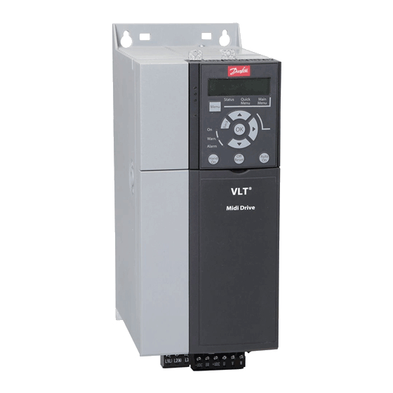
Danfoss VLT Midi Drive FC 280 Design Manual
Hide thumbs
Also See for VLT Midi Drive FC 280:
- Operating manual (146 pages) ,
- Programming manual (139 pages) ,
- Installation manual (96 pages)

Related Manuals for Danfoss VLT Midi Drive FC 280


Summary of Contents for Danfoss VLT Midi Drive FC 280
- Page 1 MAKING MODERN LIVING POSSIBLE Design Guide ® Midi Drive FC 280 vlt-drives.danfoss.com...
-
Page 3: Table Of Contents
2.4.3 Scaling of Analog and Pulse References and Feedback 2.4.4 Dead Band Around Zero 2.5 PID Control 2.5.1 Speed PID Control 2.5.2 Process PID Control 2.5.3 Process Control Relevant Parameters 2.5.4 Example of Process PID Control MG07B102 Danfoss A/S © 03/2016 All rights reserved. - Page 4 4.3.3 STO Commissioning Test 4.3.4 Test for STO Applications in Manual Restart Mode 4.3.5 Test for STO Applications in Automatic Restart Mode 4.4 Maintenance and Service for STO 4.5 STO Technical Data Danfoss A/S © 03/2016 All rights reserved. MG07B102...
- Page 5 5.6.3 Frequency Converter with Modbus RTU 5.7 Network Configuration 5.8 Modbus RTU Message Framing Structure 5.8.1 Introduction 5.8.2 Modbus RTU Telegram Structure 5.8.3 Start/Stop Field 5.8.4 Address Field 5.8.5 Function Field 5.8.6 Data Field MG07B102 Danfoss A/S © 03/2016 All rights reserved.
- Page 6 7.3 Motor Output and Motor Data 7.4 Ambient Conditions 7.5 Cable Specifications 7.6 Control Input/Output and Control Data 7.7 Connection Tightening Torques 7.8 Fuses and Circuit Breakers 7.9 Efficiency 7.10 Acoustic Noise Danfoss A/S © 03/2016 All rights reserved. MG07B102...
- Page 7 Contents Design Guide 7.11 dU/dt Conditions 7.12 Special Conditions 7.12.1 Manual Derating 7.12.2 Automatic Derating Index MG07B102 Danfoss A/S © 03/2016 All rights reserved.
-
Page 8: Introduction
Supplementary publications and manuals are available Maximum motor frequency. from Danfoss. See vlt-drives.danfoss.com/Support/Technical- Documentation/ for listings. Minimum motor frequency. Rated motor frequency (nameplate data). Motor current (actual). Nominal motor current (nameplate data). Danfoss A/S © 03/2016 All rights reserved. MG07B102... -
Page 9: References
24 V DC (maximum 40 mA) signal. A signal transmitted to the analog inputs 53 or 54 can be voltage or current. Digital signal processor. Binary reference A signal transmitted to the serial communication port. MG07B102 Danfoss A/S © 03/2016 All rights reserved. - Page 10 Power factor = Restart is prevented until the cause of the fault has 3 x U x I disappeared, and the trip state is cancelled by activating cosϕ 1 = 1, therefore: For FC 280 frequency converters, Danfoss A/S © 03/2016 All rights reserved. MG07B102...
-
Page 11: Document And Software Version
Variable torque characteristics used for pumps and fans. properly installed, maintained, and used as intended. Danfoss CE labels comply with the Low Voltage Directive, If compared with standard voltage/frequency ratio control, and Danfoss provides a declaration of conformity at... -
Page 12: Safety
Refer to the operating instructions shipped with the unit, and available online for: • Discharge time. • Detailed safety instructions and warnings. Strict adherence to safety precautions and notices is mandatory for safe operation of the frequency converter. Danfoss A/S © 03/2016 All rights reserved. MG07B102... -
Page 13: Product Overview
Power range [kW (hp)] 0.37–1.5 (0.5–2.0) 2.2 (3.0) – – – single- phase 200–240 V Table 2.1 Enclosure Sizes 1) Single-phase and 3-phase 200–240 V products are launched on the market later. MG07B102 Danfoss A/S © 03/2016 All rights reserved. -
Page 14: Electrical Installation
*** Switch S801 (bus terminal) can be used to enable termination on the RS485 port (terminals 68 and 69). **** Refer to chapter 4 Safe Torque Off (STO) for the correct STO wiring. Danfoss A/S © 03/2016 All rights reserved. MG07B102... - Page 15 Motor, 3-phase and PE Output contactor (generally not recommended) 8 Mains, single-phase, 3-phase, and reinforced PE Grounding rail (PE) Control wiring Cable shielding (stripped) Equalizing minimum 16 mm (6 AWG) Illustration 2.2 Typical Electrical Connection MG07B102 Danfoss A/S © 03/2016 All rights reserved.
-
Page 16: Motor Connection
Connect the 3-phase motor wiring to terminals 96 (U), 97 (V), and 98 (W), as shown in Illustration 2.3. Tighten the terminals in accordance with the information provided in chapter 7.7 Connection Tightening Torques. Danfoss A/S © 03/2016 All rights reserved. MG07B102... -
Page 17: Ac Mains Connection
Illustration 2.5 Mains, Motor, and Grounding Connection for 3- RFI filter screw is removed. Removing the RFI phase Units (K1, K2, K3) screw prevents damage to the DC link and reduces ground capacity currents in accordance with IEC 61800-3. MG07B102 Danfoss A/S © 03/2016 All rights reserved. -
Page 18: Control Terminal Types
Parameter 5-12 Ter input, digital minal 27 Digital output, or pulse Input DI [2] Coast output. The Parameter 5-30 Ter inverse default setting is minal 27 Digital DO [0] No digital input. Output operation Danfoss A/S © 03/2016 All rights reserved. MG07B102... -
Page 19: Wiring To Control Terminals
The function is used in mechanically robust applications, but the See chapter 7.5 Cable Specifications for control terminal accuracy is limited. Open-loop torque function cable sizes and chapter 3 Application Examples for typical control cable connections. MG07B102 Danfoss A/S © 03/2016 All rights reserved. - Page 20 PID controller by adding more functions. For example, feed forward control, clamping, reference/feedback filter, and gain scaling. Danfoss A/S © 03/2016 All rights reserved. MG07B102...
-
Page 21: Control Principle
In the configuration shown in Illustration 2.10, parameter 1-01 Motor Control Principle is set to [1] VVC parameter 1-00 Configuration Mode is set to [0] Speed open loop. The resulting reference from the reference handling system MG07B102 Danfoss A/S © 03/2016 All rights reserved. -
Page 22: Internal Current Control In Vvc + Mode
Illustration 2.12 NLCP Control Keys Local reference forces the configuration mode to open loop, independent of the setting in parameter 1-00 Configu- ration Mode. Local reference is restored when the frequency converter powers down. Danfoss A/S © 03/2016 All rights reserved. MG07B102... -
Page 23: Reference Handling
Speed up/ speed down No function P 16-02 Analog ref. 200% Ref. in % Pulse ref. -200% Local bus ref. DigiPot No function Analog ref. Pulse ref. Local bus ref. DigiPot Illustration 2.13 Remote Reference MG07B102 Danfoss A/S © 03/2016 All rights reserved. -
Page 24: Reference Limits
0, unless parameter 1-00 Configuration Mode is set to [3] Process. In that case, the following relations between the resulting reference (after clamping) and the sum of all references are as shown in Illustration 2.16. Danfoss A/S © 03/2016 All rights reserved. MG07B102... -
Page 25: Scaling Of Preset References And Bus References
Min–Max, 0% reference equals minimum reference and 100% reference equals maximum reference. • When parameter 3-00 Reference Range is set to [1] -Max–+Max, -100% reference equals -maximum reference, and 100% reference equals maximum reference. MG07B102 Danfoss A/S © 03/2016 All rights reserved. -
Page 26: Dead Band Around Zero
Illustration 2.18 Size of Dead Band Case 1: Positive reference with dead band, digital input to trigger reverse, part I Illustration 2.19 shows how reference input with limits inside minimum to maximum limits clamps. Danfoss A/S © 03/2016 All rights reserved. MG07B102... - Page 27 High Reversing Limits Speed Setpoint according to min max speed.!!! Motor PID Range: Motor Motor -8 Hz control +8 Hz Illustration 2.19 Clamping of Reference Input with Limits inside Minimum to Maximum MG07B102 Danfoss A/S © 03/2016 All rights reserved.
- Page 28 High Reversing Limits Speed Setpoint according to min max speed.!!! Motor PID Range: Motor Motor –10 Hz control +10 Hz Illustration 2.20 Clamping of Reference Input with Limits outside -Maximum to +Maximum Danfoss A/S © 03/2016 All rights reserved. MG07B102...
-
Page 29: Pid Control
(PPR): Encoder PPR Parameter 7-06 Speed PID Lowpass Filter Time 10 ms 1024 5 ms 2048 2 ms 4096 1 ms Table 2.6 Speed Control Parameters MG07B102 Danfoss A/S © 03/2016 All rights reserved. - Page 30 Check that the ramp settings are within frequency Parameter 3-41 Ramp 1 Default setting converter capabilities and allowed application operating Ramp Up Time specifications. Parameter 3-42 Ramp 1 Default setting Ramp Down Time Danfoss A/S © 03/2016 All rights reserved. MG07B102...
- Page 31 7-0* Speed PID Ctrl. 8) Finish: Parameter 0-50 LCP Copy [1] All to LCP Save the parameter setting to the LCP for safe keeping. Table 2.7 Programming Order for Speed PID Control MG07B102 Danfoss A/S © 03/2016 All rights reserved.
-
Page 32: Process Pid Control
% [unit] [unit] [speed] To motor Scale to control speed -100% *(-1) Feedback 100% Handling % [unit] -100% P 7-30 P 4-10 normal/inverse Motor speed direction Illustration 2.22 Process PID Control Diagram Danfoss A/S © 03/2016 All rights reserved. MG07B102... -
Page 33: Process Control Relevant Parameters
Constant (Analog term. 54) The low-pass filter improves steady state performance, but selecting a too long filter time deteriorates the dynamic performance of the process PID control. Table 2.9 Process Control Parameters MG07B102 Danfoss A/S © 03/2016 All rights reserved. -
Page 34: Example Of Process Pid Control
When the motor is connected to the frequency converter with straight forward phase order as U-U; V-V; W-W, the motor shaft usually turns clockwise seen into shaft end. Press [Hand On]. Check the shaft direction by applying a manual reference. Danfoss A/S © 03/2016 All rights reserved. MG07B102... - Page 35 High Limit [Hz] Parameter 4-19 Max Output Frequency Set parameter 6-19 Terminal 53 mode and parameter 6-29 Terminal 54 mode to voltage or current mode. 5) Scale analog inputs used for reference and feedback: MG07B102 Danfoss A/S © 03/2016 All rights reserved.
-
Page 36: Process Controller Optimization
Lower the proportional gain by 40–60%. Set parameter 7-34 Process PID Integral Time to 20 s and reduce the value until the feedback signal again begins to vary continuously. Increase the Danfoss A/S © 03/2016 All rights reserved. MG07B102... -
Page 37: Ziegler Nichols Tuning Method
PI-control 0.45 x K 0.833 x P – To tune the PID controls of the frequency converter, Danfoss recommends the Ziegler Nichols tuning method. PID tight 0.6 x K 0.5 x P 0.125 x P control NOTICE PID some 0.33 x K... -
Page 38: Emc Emission And Immunity
If placing the shield on a mounting plate for the frequency converter, use a metal mounting plate to convey the shield currents back to the unit. Ensure good electrical contact from the mounting plate through the mounting screws to the frequency converter chassis. Danfoss A/S © 03/2016 All rights reserved. MG07B102... -
Page 39: Emc Emission Requirements
1) Frequency range from 150 kHz to 30 MHz is not harmonized between IEC/EN 61800-3 and EN 55011 and not mandatorily included. 2) Low earth leakage current. Compatible to run on ELCB/IT mains. MG07B102 Danfoss A/S © 03/2016 All rights reserved. -
Page 40: Emc Immunity Requirements
• EN 61000-4-6 (IEC 61000-4-6) Conducted immunity: Simulation of the effect from radio-transmission equipment joined by connection cables. The immunity requirements should follow product standard IEC 61800-3 and Danfoss internal standards. See Table 2.13 for details. Voltage range: 380–480 V... -
Page 41: Galvanic Isolation
3 Isolation between STO inputs and IGBT circuit 4 Customer relay Illustration 2.27 Galvanic Isolation The functional galvanic isolation (a and b on Illustration 2.27) is for the 24 V back-up option and the RS485 standard bus interface. MG07B102 Danfoss A/S © 03/2016 All rights reserved. -
Page 42: Brake Functions
Dimension RCDs according to the system configu- frequency converter cannot provide a safe control of a ration and environmental considerations. mechanical brake. Include a redundancy circuitry for the brake control in the total installation. Danfoss A/S © 03/2016 All rights reserved. MG07B102... -
Page 43: Dynamic Braking
To handle higher demands by generatoric braking, a brake resistor is necessary. Using a brake resistor ensures that the Danfoss offers brake resistors with duty cycles of 10% and heat is absorbed in the brake resistor and not in the 40%. -
Page 44: Smart Logic Controller
In this situation, the ramp-down time is extended. The resistance of the brake resistor should not be higher than the value recommended by Danfoss. For brake NOTICE resistors with a higher ohmic value, the 160% braking torque may not be achieved because the frequency OVC can be activated when running a PM motor (when converter might cut out for safety reasons. -
Page 45: Extreme Running Conditions
However, fault messages may 13-52.0 State 2 13-51.1 Stop appear. 13-52.1 event P13-02 Stop event P13-02 State 4 13-51.3 13-52.3 State 3 13-51.2 13-52.2 Stop event P13-02 Illustration 2.34 Sequence with 3 Events/Actions MG07B102 Danfoss A/S © 03/2016 All rights reserved. -
Page 46: Motor Thermal Protection
Torque limit is controlled in parameter 4-16 Torque Limit Motor Mode and parameter 4-17 Torque Limit Generator Mode. Parameter 14-25 Trip Delay at Torque Limit controls the time before the torque limit warning trips. Danfoss A/S © 03/2016 All rights reserved. MG07B102... -
Page 47: Application Examples
Frequency converter. Illustration 3.1 24 V Encoder • Encoder as feedback system. • Brake resistor for dynamic brake. • Transmission. • Load. Applications demanding mechanical brake control usually need a brake resistor. MG07B102 Danfoss A/S © 03/2016 All rights reserved. -
Page 48: Application Examples
If terminal 12 and 27 are A OUT not connected, set Table 3.3 Analog Speed Reference (Current) parameter 5-12 Terminal 27 Digital Input to [0] No operation. Table 3.1 AMA with T27 Connected Danfoss A/S © 03/2016 All rights reserved. MG07B102... -
Page 49: Start/Stop
Preset ref. 0 A OUT Preset ref. 1 Preset ref. 2 Preset ref. 3 100% * = Default value Table 3.5 Speed Up/Speed Down Notes/comments: Table 3.6 Start/Stop with Reversing and 4 Preset Speeds MG07B102 Danfoss A/S © 03/2016 All rights reserved. -
Page 50: External Alarm Reset
1-90 Motor Thermal continues, and the warning Protection to [1] Thermistor disappears. Relay 1 persists A OUT until [Off/Reset] is pressed. warning. Table 3.9 Using SLC to Set a Relay Table 3.8 Motor Thermistor Danfoss A/S © 03/2016 All rights reserved. MG07B102... -
Page 51: Safe Torque Off (Sto)
80 ms. To terminate STO, the 2 signals must both be at high level for at least 20 ms. Refer to chapter 7.6 Control Input/Output and Control Data for the voltage levels and input current of STO terminals. MG07B102 Danfoss A/S © 03/2016 All rights reserved. -
Page 52: Safety Precautions For Sto
(24 V), 37, and 38. Cutting or breaking the jumper is not sufficient to avoid short-circuiting. See the jumper in Illustration 4.3. Safety device Illustration 4.4 STO Wiring in 1 Cabinet, Frequency Converter Provides the Supply Voltage Danfoss A/S © 03/2016 All rights reserved. MG07B102... -
Page 53: Sto Commissioning
STO Applications in Manual Restart Mode if STO is set to manual restart mode. • Follow the instructions in chapter 4.3.5 Test for STO Applications in Automatic Restart Mode if STO is set to automatic restart mode. MG07B102 Danfoss A/S © 03/2016 All rights reserved. -
Page 54: Test For Sto Applications In Manual Restart Mode
188, STO Function Fault Torque Off W68 is logged in bit 30 of is logged in parameter 15-30 Alarm Log: Error parameter 16-92 Warning Word. Code. Reapply 24 V DC to terminals 37 and 38. Danfoss A/S © 03/2016 All rights reserved. MG07B102... -
Page 55: Sto Technical Data
1) Reaction time is the amount of time from an input signal condition that triggers the STO until the torque is off on the motor. 2) For proof test procedure, refer to chapter 4.4 Maintenance and Service for STO. MG07B102 Danfoss A/S © 03/2016 All rights reserved. -
Page 56: Rs485 Installation And Set-Up
69 (N-) on the main control board of the cables to maintain the same ground potential throughout frequency converter. the network, particularly in installations with long cables. Connect the cable shield to the cable clamps. Danfoss A/S © 03/2016 All rights reserved. MG07B102... -
Page 57: Hardware Set-Up
The default baud rate depends on the The FC protocol, also referred to as FC bus or standard bus, protocol selected in is the Danfoss standard fieldbus. It defines an access parameter 8-30 Protocol. technique according to the master/slave principle for communications via a fieldbus. -
Page 58: Fc With Modbus Rtu
1) The 10 represents the fixed characters, while the n is variable Parameter 8-33 Parity / Even parity, 1 stop bit (default) (depending on the length of the text). Stop Bits Table 5.3 Parameters to Enable the Protocol Danfoss A/S © 03/2016 All rights reserved. MG07B102... -
Page 59: Frequency Converter Address (Adr)
Table 5.6 Response PCD1 PCD2 If the command cannot be performed, the slave sends this Illustration 5.7 Text Block response 0111 Command cannot be performed and issues the following fault report in Table 5.7. MG07B102 Danfoss A/S © 03/2016 All rights reserved. -
Page 60: Parameter Number (Pnu)
When a slave responds to a parameter request (read command), the present parameter value in the PWE block is transferred and returned to the master. If a parameter contains several data options, for example Danfoss A/S © 03/2016 All rights reserved. MG07B102... -
Page 61: Process Words (Pcd)
3-41 Ramp 1 Ramp Up Time is -2, that E19E 0000 H 0000 H 03E8 is, 0.01. Parameter 3-41 Ramp 1 Ramp Up Time is of the type high Unsigned 32. Illustration 5.9 Telegram MG07B102 Danfoss A/S © 03/2016 All rights reserved. -
Page 62: Modbus Rtu
5.6.1 Prerequisite Knowledge action, the slave constructs and sends an error message. Alternatively, a timeout occurs. Danfoss assumes that the installed controller supports the 5.6.3 Frequency Converter with Modbus interfaces in this manual, and strictly observes all requirements and limitations stipulated in the controller and frequency converter. -
Page 63: Modbus Rtu Message Framing Structure
This code tells the master what kind of error occurred, or the reason for the exception. Also refer to Table 5.14 Typical Modbus RTU Telegram Structure chapter 5.8.10 Function Codes Supported by Modbus RTU and chapter 5.8.11 Modbus Exception Codes. MG07B102 Danfoss A/S © 03/2016 All rights reserved. -
Page 64: Data Field
The function code field already specifies a holding register operation. Therefore, the 4XXXX reference is implicit. Holding register 40108 is addressed as register 006Bhex (107 decimal). Danfoss A/S © 03/2016 All rights reserved. MG07B102... - Page 65 Table 5.18 Address/Registers 1) Value written in the Modbus RTU telegram must be 1 or less than the register number. For example, Read Modbus Register 1 by writing value 0 in the telegram. MG07B102 Danfoss A/S © 03/2016 All rights reserved.
-
Page 66: How To Control The Frequency Converter
A value of 11300 (decimal), means that the parameter is set to 1113.00. For information on the parameters, size, and conversion ® index, see the VLT Midi Drive FC 280 Programming Guide. Danfoss A/S © 03/2016 All rights reserved. MG07B102... -
Page 67: Storage Of Data
-1 in Modbus. range from 1 register (2 characters) up to 10 registers (20 For example, coil 33 is addressed as coil 32. characters). 5.10 Examples The following examples show various Modbus RTU commands. MG07B102 Danfoss A/S © 03/2016 All rights reserved. -
Page 68: Force/Write Single Coil (05 Hex)
Coil addresses start at 0, that is, coil 17 is addressed as Number of points HI Number of points LO 02 – (parameter 3-03 Maximum Reference is 32 bits long, that is, 2 registers) Error check (CRC) – Table 5.28 Query Danfoss A/S © 03/2016 All rights reserved. MG07B102... -
Page 69: Preset Single Register (06 Hex)
Field name Example (hex) Slave address Function Register address HI Register address LO Preset data HI Preset data LO Error check (CRC) – Table 5.31 Response MG07B102 Danfoss A/S © 03/2016 All rights reserved. -
Page 70: Danfoss Fc Control Profile
Bit 09=0: Ramp 1 is active (parameter 3-41 Ramp 1 Ramp Up Time to parameter 3-42 Ramp 1 Ramp Down Time). Bit 09=1: Ramp 2 (parameter 3-51 Ramp 2 Ramp Up Time to parameter 3-52 Ramp 2 Ramp Down Time) is active. Danfoss A/S © 03/2016 All rights reserved. MG07B102... -
Page 71: Status Word According To Fc Profile (Stw)
15 14 13 12 11 10 9 8 7 6 5 4 3 2 1 0 no.: Bit 07, No warning/warning Illustration 5.14 Status Word Bit 07=0: There are no warnings. Bit 07=1: A warning has occurred. MG07B102 Danfoss A/S © 03/2016 All rights reserved. - Page 72 Bit 14=1: The current limit in parameter 4-18 Current Limit is exceeded. Bit 15, Timer OK/limit exceeded Bit 15=0: The timers for motor thermal protection and thermal protection are not exceeded 100%. Bit 15=1: 1 of the timers exceeds 100%. Danfoss A/S © 03/2016 All rights reserved. MG07B102...
-
Page 73: Bus Speed Reference Value
Par.3-00 set to Reverse Forward (1) -max- +max Par.3-03 Par.3-03 Max reference Max reference 100% (0hex) (4000hex) Par.3-00 set to Forward (0) min-max Par.3-02 Par.3-03 Max reference Min reference Illustration 5.16 Reference and MAV MG07B102 Danfoss A/S © 03/2016 All rights reserved. -
Page 74: Type Code And Selection
2800 size D 132B0366 ® 132B0368 24 V DC Supply MCB 106 LCP Remote Mounting Kit, w/3m cable 132B0102 LCP Mounting Kit, w/no LCP 130B1117 Table 6.1 Ordering Numbers for Options and Accessories Danfoss A/S © 03/2016 All rights reserved. MG07B102... -
Page 75: Ordering Numbers: Brake Resistors
6.2 Ordering Numbers: Brake Resistors Danfoss offers a wide variety of different resistors that are specially designed for our frequency converters. See chapter 2.9.4 Control with Brake Function for the dimensioning of brake resistors. This section lists the ordering numbers for the brake resistors. -
Page 76: Ordering Numbers: Brake Resistors 40
3203 4 (12) (11.534) Table 6.3 FC 280 - Mains: 380–480 V (T4), 40% Duty Cycle 1) All cabling must comply with national and local regulations on cable cross-sections and ambient temperature. Danfoss A/S © 03/2016 All rights reserved. MG07B102... -
Page 77: Specifications
Weight, enclosure protection rating IP20 [kg 2.3 (5.1) 2.3 (5.1) 2.3 (5.1) 2.3 (5.1) 2.3 (5.1) 2.5 (5.5) 3.6 (7.9) (lb)] 96.2 97.0 97.2 97.4 97.4 97.6 97.5 Efficiency [%] Table 7.1 Mains Supply 3x380–480 V AC MG07B102 Danfoss A/S © 03/2016 All rights reserved. -
Page 78: Mains Supply (3-Phase)
(though typically only 4 W extra for a fully loaded control card or fieldbus). For power loss data according to EN 50598-2, refer to www.danfoss.com/vltenergyefficiency. 2) Measured using 50 m (164 ft) shielded motor cables at rated load and rated frequency. For energy efficiency class, see chapter 7.4 Ambient Conditions. -
Page 79: Motor Output And Motor Data
Switching frequency factory setting. • Switching pattern factory setting. • ° C (113 ° F). Open type: Surrounding air temperature 45 • ° C (113 ° F). Type 1 (NEMA kit): Ambient temperature 45 MG07B102 Danfoss A/S © 03/2016 All rights reserved. -
Page 80: Cable Specifications
100 Hz The analog inputs are galvanically isolated from the supply voltage (PELV) and other high-voltage terminals. 1) Terminal 53 supports only voltage mode and can also be used as digital input. Danfoss A/S © 03/2016 All rights reserved. MG07B102... - Page 81 DC bus RS485 Illustration 7.1 Galvanic Isolation NOTICE HIGH ALTITUDE For installation at altitudes above 2000 m (6562 ft), contact Danfoss hotline regarding PELV. Pulse inputs Programmable pulse inputs Terminal number pulse 29, 33 Maximum frequency at terminal 29, 33...
- Page 82 Speed control range (open loop) 1:100 of synchronous speed ±0.5% of nominal speed Speed accuracy (open loop) ±0.1% of nominal speed Speed accuracy (closed loop) All control characteristics are based on a 4-pole asynchronous motor. Danfoss A/S © 03/2016 All rights reserved. MG07B102...
-
Page 83: Connection Tightening Torques
(first fault). damage to the frequency converter. Branch circuit protection Danfoss recommends using the fuses and circuit breakers Protect all branch circuits in an installation (including in Table 7.4 to ensure compliance with UL or IEC 61800-5-1. switch gear and machines) against short circuit and For non-UL applications, design circuit breakers for overcurrent according to national/international regulations. -
Page 84: Efficiency
η SYSTEM MOTOR Specifications: 1.01 0.99 0.98 0.97 0.96 0.95 0.94 0.93 0.92 100% 150% 200% % Speed 100% load 75% load 50% load 25% load Illustration 7.2 Typical Efficiency Curves Danfoss A/S © 03/2016 All rights reserved. MG07B102... -
Page 85: Acoustic Noise
The following dU/dt data are measured at the motor 5 (16.4) 0.0712 0.484 5.44 terminal side: 50 (164) 0.224 0.594 2.11 Table 7.11 dU/dt Data for FC 280, 1.5 kW (2.0 hp), 3x200–240 V MG07B102 Danfoss A/S © 03/2016 All rights reserved. -
Page 86: Special Conditions
RPM in constant torque applications. Illustration 7.5 K3 Derating Curve • Ambient temperature – above 45 °C (113 °F), for details, see Illustration 7.3, Illustration 7.4, Illustration 7.5, Illustration 7.6, and Illustration 7.7. Danfoss A/S © 03/2016 All rights reserved. MG07B102... -
Page 87: Automatic Derating
High motor load. • Low motor speed. • Protection signals (overvoltage/undervoltage, overcurrent, ground fault, and short circuit) are triggered. As a response to a critical level, the frequency converter adjusts the switching frequency. MG07B102 Danfoss A/S © 03/2016 All rights reserved. -
Page 88: Index
Hold output frequency............... 68 Customer relay..................52 IEC 61800-3..................15, 77 Data type, supported................58 IND......................58 DC brake....................68 Index (IND)....................58 Dead band....................24 Dead band around 0................24 Derating....................77 Danfoss A/S © 03/2016 All rights reserved. MG07B102... - Page 89 Speed PID control................. 27 NLCP control key................... 20 Speed reference..................46 Standard and compliance for STO............ 9 Static overload in VVC+ mode............44 Open loop....................80 Status word..................... 69 Output current..................79 MG07B102 Danfoss A/S © 03/2016 All rights reserved.
- Page 90 Switching on the output..............43 Synchronous motor speed..............7 Telegram length (LGE)................. 56 Terminal tightening torque.............. 81 Thermistor..................8, 48 Torque characteristic..................77 control....................17 Trip........................ 8 Voltage level................... 78 VVC+..................... 9, 20 Danfoss A/S © 03/2016 All rights reserved. MG07B102...
- Page 91 Index Design Guide MG07B102 Danfoss A/S © 03/2016 All rights reserved.
- Page 92 Danfoss can accept no responsibility for possible errors in catalogues, brochures and other printed material. Danfoss reserves the right to alter its products without notice. This also applies to products already on order provided that such alterations can be made without subsequential changes being necessary in specifications already agreed. All trademarks in this material are property of the respective companies.
Need help?
Do you have a question about the VLT Midi Drive FC 280 and is the answer not in the manual?
Questions and answers