Sign In
Upload
Download
Table of Contents
Contents
Add to my manuals
Delete from my manuals
Share
URL of this page:
HTML Link:
Bookmark this page
Add
Manual will be automatically added to "My Manuals"
Print this page
×
Bookmark added
×
Added to my manuals
Manuals
Brands
Stone Manuals
Construction Equipment
Rhino 43 Series
Operator's manual
Stone Rhino 43 Series Operator's Manual
Vibratory dirt roller
Hide thumbs
1
2
Table Of Contents
3
4
5
6
7
8
9
10
11
12
13
14
15
16
17
18
19
20
21
22
23
24
25
26
27
28
29
30
31
32
33
34
35
36
37
38
39
40
41
42
43
44
45
46
47
48
49
50
51
52
53
54
55
56
57
58
59
60
61
62
63
64
65
66
page
of
66
Go
/
66
Contents
Table of Contents
Troubleshooting
Bookmarks
Table of Contents
Table of Contents
Limited Warranty
Foreword
Introduction
Technical Data
43 Specifications
Engine RPM
Machine Data
Operator Controls
Machine Sound Level Test
Locking Bar
Machine Dimensions
Health & Safety
Operation
Delivery Inspection
Break-In Period
Before Starting
Warming Engine
Fuel
Engine Oil Level
Air Filter / Fuel Level
Hydraulic Oil
Engine Coolant
Tires/Lug Nuts
Drum/Scrapers
Cleaning
Eccentrics
Visual Inspection
Mounting/Dismounting the Machine
Starting the Machine
Cold Weather Starting
To Operate
Operation on Slopes
Forward/Reverse/Neutral
Shutting the Machine off
Parking the Machine
Safety Features
Seat
Steering Controls
Operator Controls
Gauges
Lights
Air Cleaner
Compaction Tips
Locking Bar
Transportation
Tie Downs
Towing (Bypass)
Storage
Maintenance
Important
Maintenance Schedule
Important Maintenance Information
Additional Service Information
Hydraulic Oil/Filter
Hydraulic Breather
Adding Engine Coolant
Disposing of Coolant
Air Cleaner
Air Cleaner Replacement
Element Storage
In Line Fuel Filter
Engine Fuel Filter
Fuel Tank / Fuel Lines
Bleeding Air from Fuel System
Fan/Alternator Belt
Grease Fittings / Frame Hinge
Blade Pins
Battery
Battery Installation
Charging/Jumping Battery
Engine Crankcase Vent Tube
Engine Valve Clearance
Emission Regulation/Engine RPM
Fuel Injectors
Test Fuel Injection Nozzles
Fuel Tank / Fuel Lines
Hydraulic Hoses/Connections
Forward/Reverse/Neutral Adjustment
Neutral Interlock
Control Cables: Forward/Reverse, Throttle, Blade
Eccentrics / Eccentric Housing Oil
Charge System
Panel Fuse 20 Amp
Engine Installation Guidelines
Engine Mounting
Hardware
Loctite / Scrapers
Roll over Protective Structures (ROPS)
Maintenance of Rops/Seat Belts
Horn/Back-Up
Troubleshooting
Service Record
Parker Hose/Connections Warranty
Notes
Advertisement
Quick Links
1
43 Specifications
2
Hydraulic Oil
Download this manual
Operator Manual
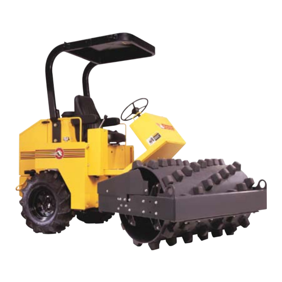
Rhino
Vibratory Dirt Roller
TM
SD-43, SD-54, PD-43
Models:
PD-54, PDB-43, PDB-54
REVISION A 10/2011
P/N 56957
Table of
Contents
Previous
Page
Next
Page
1
2
3
4
5
Advertisement
Table of Contents
Need help?
Do you have a question about the Rhino 43 Series and is the answer not in the manual?
Ask a question
Questions and answers
Related Manuals for Stone Rhino 43 Series
Construction Equipment Stone RP522 Operator's Manual
Reversible plate (36 pages)
Construction Equipment Stone 1050PM Service & Parts Manual
Plaster/mortar mixer (69 pages)
Construction Equipment Stone Champion 655PMP Service And Parts Manual
(52 pages)
Construction Equipment Stone WolfPac 3100 Service & Parts Manual
(124 pages)
Construction Equipment Stone Mud Buggy SB1600 Service & Parts Manual
(68 pages)
Construction Equipment Stone WolfPac 3100 Operator's Manual
Rops option. asphalt roller (28 pages)
Construction Equipment Stone TR24 Operator's Manual
Bulldog trench roller (52 pages)
Construction Equipment Stone BULLDOG TR24 Operator's Manual
Manual/remote, trench roller (56 pages)
Construction Equipment Stone HM1290 Operator's Manual
Hydraulic mixer plaster, mortar, fireproofing. (20 pages)
Construction Equipment Stone WolfPac 2500 Operator's Manual
1-1/4 ton static ride on (28 pages)
Construction Equipment Stone CHAMPION 855PMP Operator's Manual
Plastic drum plaster/mortar mixer (24 pages)
Construction Equipment Stone WolfPac 6100 Operator's Manual
Vibratory asphalt roller (128 pages)
Construction Equipment Stone CHAMPION 465PM Operator's Manual
Plaster mortar mixer (24 pages)
Construction Equipment Stone 45CM Operator's Manual
Concrete mixer (20 pages)
Construction Equipment Stone 95CMP Operator's Manual
Concrete mixer (20 pages)
This manual is also suitable for:
Rhino 54 series
Rhino sd-43
Rhino sd-54
Rhino pd-43
Rhino pd-54
Rhino pdb-43
...
Show all
Rhino pdb-54
Table of Contents
Print
Rename the bookmark
Delete bookmark?
Delete from my manuals?
Login
Sign In
OR
Sign in with Facebook
Sign in with Google
Upload manual
Upload from disk
Upload from URL


Need help?
Do you have a question about the Rhino 43 Series and is the answer not in the manual?
Questions and answers