Advertisement
Quick Links
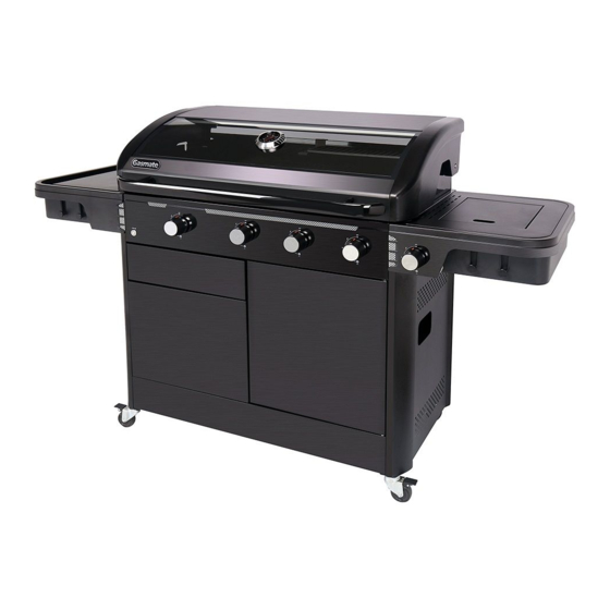
CORVUS
4 BURNER BBQ
Model No. GM172-151
Matt powder coated double-skinned roasting hood
with viewing window
54.6MJ/h total burner output from 3 x U-shaped
stainless steel burners and 1 x ring stainless steel
burner
11.2MJ/h flush mounted cast iron side burner
LED illuminated control knobs with rotary piezo ignition
for easy lighting
Important: Retain these instructions for future use.
Gasmate® is a registered trademark of: Sitro Group Australia Pty Ltd www.gasmate.com.au
Push-to-open drawers and cupboard inset into powder
coated trolley
Versatile cast iron grilling system with 2 x hotplates, 2 x
half-moon grills, 1 x circle insert and warming rack
Assembled dimensions (mm): 1805 W x 1175 H x 625 D
Total cooking area (mm): 940 W x 480 D
Approved to NZ Standards
Aber Living - Hamilton, N.Z. www.gasmate.co.nz
5202-05/20
Advertisement

Subscribe to Our Youtube Channel
Related Manuals for Gasmate CORVUS GM172-151


Summary of Contents for Gasmate CORVUS GM172-151
- Page 1 LED illuminated control knobs with rotary piezo ignition Approved to NZ Standards for easy lighting Important: Retain these instructions for future use. Gasmate® is a registered trademark of: Sitro Group Australia Pty Ltd www.gasmate.com.au Aber Living - Hamilton, N.Z. www.gasmate.co.nz 5202-05/20...
- Page 2 GENERAL INFORMATION Always ensure the barbecue is kept away from flammable materials and the gas cylinder clear of any heat source. IMPORTANT When changing over from an empty gas cylinder to a full Read these instruction carefully prior to use. one make sure this procedure is carried out in a flame Familiarise yourself with the appliance before free atmosphere.
- Page 3 GENERAL INFORMATION FOR YOUR SAFETY • This barbecue must not be used indoors. • Only use in well ventilated areas. Failure to comply with these instructions could result • CARBON MONOXIDE HAZARD - USING THIS in a fire or explosion which could cause serious bodily injury, death or property damage.
- Page 4 GENERAL INFORMATION Location of your Barbecue Tools You Will Need DO NOT use your barbecue in garages, porches, Standard Phillips-head screw driver (or cordless drill breezeways, sheds or other enclosed areas. Your and bits) and Adjustable spanner (open ended shifter) or barbecue is to be used OUTDOORS.
- Page 5 EXPLODED DIAGRAM Description Description Left front corner brace Gas cylinder rest Left side panel Rear panel Left rear corner brace Left slideway support for drawers Left side brace Right slideway support for drawers Right front corner brace Drawer base Right side panel Small drawer front Right rear corner brace Left support for large drawer front...
- Page 6 EXPLODED DIAGRAM B 0-a B 0-a B 0-b B 0-c B 0-b Description Description Gas grill assembly Cooking grate support Left shelf Cooking grate Right shelf Warming rack support Side burner Warming rack Side burner cover Battery holder Side burner knob Grease tray Round flame tamer Heat reflective plate...
- Page 7 HARDWARE Description Screw M6x15 Lock washer and nut M6 Washer M6 Screw M4x10 Screw M5x12 Screw M4x12 Screw M6x12 Screw M4x12 Hex Wrench 10 / 13 Hex Wrench 14/ 16 Philips Screwdriver PH 3 PARTS LIST Description Description Description Handle Drawers Right shelf Insulated lid...
- Page 8 ASSEMBLY INSTRUCTIONS STEP 1 Attach front leg (A1) and rear leg (A3) to left hand side panel (A2) using 6 x C1 screws. Attach support bracket (A4) using 2 x C1 screws. Attach front leg (A5) and rear leg (A7) to left hand side panel (A6) using 6 x C1 Screws. Attach support bracket (A8) using 2 x C1 screws.
- Page 9 ASSEMBLY INSTRUCTIONS STEP 3 Attach front support brackets (A10 & A11) to front leg supports using 12 x C1 screws. + 12 x + 12 x + 12 x + 12 x + 2 x + 2 x + 5 x + 1 x + 2 x + 2 x...
- Page 10 ASSEMBLY INSTRUCTIONS STEP 5 Attach rear panel (A15) to rear support legs and base using 6 x C1 screws. + 6 x + 6 x + 6 x + 6 x + 6 x + 6 x STEP 6 Attach left hand drawer support rail panel (A16) to left hand side panel using 6 x C1 screws. + 6 x + 6 x...
- Page 11 ASSEMBLY INSTRUCTIONS STEP 7 Attach right hand side drawer support rail panel (A17) to centre base panel, rear panel and front top support bracket using 5 x C1 screws. + 5 x + 5 x + 5 x + 5 x + 5 x + 4 x + 10 x...
- Page 12 ASSEMBLY INSTRUCTIONS STEP 9 Insert assembled drawers (A18-19) & (A18-21) into drawer rails. A18-19 A18-19 A18-21 A18-22 A18-19 A18-19 + 4 x A18-22 + 4 x STEP 10 Attach top heat shield (A23) to the top of the drawer support rail panels using 4 x C1 screws Attach main door latch (A24) to drawer support rail panel using 2 x C8 screws.
-
Page 13: Step 11
ASSEMBLY INSTRUCTIONS STEP 11 Attach main door (A25) by inserting bottom door hinge into front base panel then push down on top door hinge #1 and slide into hinge support #2. + 6 x + 2 x STEP 12 + 6 x + 2 x Sit main fire box (B1) on top of cabinet (A1-25) using 6 x C1 screws and 2 x C3 washers. -
Page 14: Step
ASSEMBLY INSTRUCTIONS STEP 13 & 14 Attach side shelve (B2 & B3) using 4 x C1 screws. + 2 x + 2 x + 4 x + 2 x + 4 x + 2 x... -
Page 15: Step
ASSEMBLY INSTRUCTIONS STEP 15 Screw side burner element (B4) to gas supply hose using spanner (D1). Place side burner element cover (B5) on top of side burner element (B4). Attach side burner valve to front of side shelf using 2 x C6 screws. Push on control knob (B6) to side burner valve. -
Page 16: Step 17
ASSEMBLY INSTRUCTIONS STEP 17 Insert flame tamers (B7 & B8) over burners. STEP 18 Insert grill plates (B9) and hot plates (B10) over flame tamers. - Page 17 ASSEMBLY INSTRUCTIONS STEP 19 Insert warming rack support (B11). Insert warming rack (B12) on to warming rack support (B11). STEP 20 Insert 2x AA batteries (not included) into battery pack (B13). Connect battery pack to main lead.
- Page 18 ASSEMBLY INSTRUCTIONS STEP 21 Insert drip tray heat guard (B15) into drip tray (B14). Insert drip tray into rear of fire box. STEP 22 Insert grease tray (B16) into front supports.
- Page 19 ASSEMBLY INSTRUCTIONS STEP 23 Make sure your castors are in the locked position before starting your BBQ. Unlocked Locked...
-
Page 20: Table Of Contents
ASSEMBLY INSTRUCTIONS STEP 24 STEP 25 Step 12 Step 12 Step 13 Step 13 Step 12 Step 13 Attach the regulator to your gas cylinder. Attach the regulator to your gas cylinder. Step 12 Attach the regulator to your gas cylinder. Turn on the gas cylinder ensuring that all of the controls Turn on the gas cylinder ensuring that all of the Turn on the gas cylinder ensuring that all of the... - Page 21 GENERAL ASSEMBLY Connecting & Disconnecting to Gas Source Regulator Safety Feature All QCC regulators (the part that attaches to the gas cylinder to regulate the flow of gas) have a safety feature IMPORTANT: included that restricts gas flow in the event of a gas leak. You can inadvertently activate this safety feature without having a gas leak.
- Page 22 LIGHTING PROCEDURE Side Burner Before lighting your barbecue for the first time, read the instructions fully to ensure the barbecue is assembled Lift up the cover and ensure it is always open when correctly and is ready for use. the burner is alight. Control Knobs Push and turn the control knob anti-clockwise to HIGH whilst pressing the piezo ignitor (a single click...
- Page 23 BURNER OPERATION & IGNITION SYSTEM CHECK Problem Possible Reason Solution Valve on cylinder is closed Open valve on cylinder Burner will Control knob is closed Turn knob to high when lighting not ignite Piezo igniter is faulty Use a long barbecue match Burner has gone out Check that the gas bottle is not empty and re-ignite the burner...
- Page 24 OPERATING PROCEDURE Burn Off Cooking Surfaces Roasting We recommend operating your barbecue on its highest For best results when roasting, the outer two burners setting for 15-20 minutes prior to first use. This aids should be used on the medium setting. Use of the high removing the oils used during manufacturing.
- Page 25 CARE & MAINTENANCE As with all appliances, proper care and maintenance Cleaning Painted surfaces will keep them in top operating condition and prolong Wash with mild detergent or nonabrasive cleaner and their life. Your new gas barbecue is no exception. By warm soapy water.
- Page 26 SAFE APPLIANCE LOCATIONS Within a partial enclosure that includes an overhead cover and no more than two walls This appliance shall only be used in an above ground (see Example 2 & 3). open-air situation with natural ventilation, without Within a partial enclosure that includes an overhead stagnant areas, where gas leakage and products of cover and more than two walls, the following will apply: combustion are rapidly dispersed by wind and natural...
- Page 27 This page has been left intentionaly blank...
- Page 28 2 YEAR LIMITED WARRANTY Aber Living warrants the purchaser of this product against defects in workmanship and material, for a period of up to 24 months from the date of purchase. The warranty is non-transferable and becomes void if used for commercial or rental purposes.
Need help?
Do you have a question about the CORVUS GM172-151 and is the answer not in the manual?
Questions and answers