Table of Contents
Advertisement
Quick Links
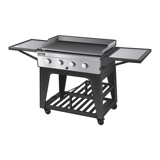
TELLUS
4 BURNER BBQ
Model No. GM165-023
Ideal heavy duty BBQ for sporting and social clubs
or anywhere large groups are entertained
Hard-wearing powder coated frame with stainless
steel fascia
Solid 5mm thick steel hotplate
Stainless steel burners with electronic ignition
Important: Retain these instructions for future use.
Gasmate® is a registered trademark of: Sitro Group Australia Pty Ltd www.gasmate.com.au
Foldable side shelves with non-slip aluminium inserts
Assembled dimensions (mm): 1765W x 615D x 965H
Total cooking area (mm): 840W x 510D
Universal LPG
Approved to NZ Standards
Aber Living - Hamilton, N.Z. www.gasmate.co.nz
5006-07/18
Advertisement
Table of Contents

Related Manuals for Gasmate TELLUS GM165-023


Summary of Contents for Gasmate TELLUS GM165-023
- Page 1 Solid 5mm thick steel hotplate Approved to NZ Standards Stainless steel burners with electronic ignition Important: Retain these instructions for future use. Gasmate® is a registered trademark of: Sitro Group Australia Pty Ltd www.gasmate.com.au Aber Living - Hamilton, N.Z. www.gasmate.co.nz 5006-07/18...
-
Page 2: General Information
GENERAL INFORMATION Gas Installation Codes • Barbecues must be used in accordance with New If you are unable to correct the leak by tightening the Zealand Standard 5601 “Gas Installations”. connections, turn off the gas and contact the supplier immediately. •... -
Page 3: Protect Children
GENERAL INFORMATION Location of your Barbecue Check Barbecue for any Damage DO NOT use your barbecue in garages, porches, sheds, Contact your supplier for assistance regarding breezeways, or other enclosed areas. Your barbecue is to replacement of any damaged or missing parts. Do not be used OUTDOORS. -
Page 4: General Assembly
GENERAL ASSEMBLY LIGHTING PROCEDURE Connecting & Disconnecting to Gas Source Burner Operation & Ignition System Check 1. Turn all the control knobs clockwise to “OFF” position. 2. With cylinder valve in ‘CLOSE’ position press the IMPORTANT: piezo igniter button (a single click is heard). Check for sparking to the burners. -
Page 5: Operating Procedure
BURNER OPERATION & IGNITION SYSTEM CHECK Problem Possible Reason Solution Valve on cylinder is closed Open valve on cylinder Burner will Control knob is closed Turn knob to high when lighting not ignite Electronic igniter is faulty Use a long barbecue match Burner has gone out Check that the gas bottle is not empty and re-ignite the burner... -
Page 6: Exploded Diagram
EXPLODED DIAGRAM Description Side Shelf Side Shelf Brackets Side Handle Side Shelf Brackets Knob Cylinder Hook Cylinder Support Bracket Trolley Brace Bar Drip Tray Side Supports Bottom Shelf Castor Support Rod Shelf Shelf Support Firebox Hotplate Drip Tray Support Beams Drip Tray Support Beams HARDWARE D. - Page 7 ASSEMBLY INSTRUCTIONS STEP 1 STEP 2 Screw all castors (14) into the underside of the bottom Attach the four legs (10,12,15,18) to the bottom shelf shelf (13) using 4 x M5x10mm (B) screws per castor. using 2 x M6x25mm (C) screws per leg. 16pcs 8pcs STEP 3...
- Page 8 ASSEMBLY INSTRUCTIONS STEP 5 STEP 6 Attach both support rods (16) into the trolley legs using Screw both side supports (11) onto the trolley legs using 4 x M6x12mm screws (A). 12 x M6x12mm screws (A). 4pcs 12pcs STEP 7 STEP 8 Screw the cylinder support bracket (7) into the base of Attach the cylinder hook (6) onto the leg side supports...
- Page 9 ASSEMBLY INSTRUCTIONS STEP 9 STEP 10 Attach the trolley brace bar (8) from the centre of the Attach the drip tray support beams (22,23) to the trolley shelf to the cylinder support using 2 x M6x12mm underside of the support rods (16) using 4 x M6x20mm screws (A).
- Page 10 ASSEMBLY INSTRUCTIONS STEP 13 STEP 14 Attach the side shelf brackets (2) onto each end of the Attach the side shelf brackets (4) onto the remaining firebox using 8 x M6x12mm screws (A), ensuring the corners using 8 x M6x12mm screws (A), ensuring that the ‘tabs’...
- Page 11 ASSEMBLY INSTRUCTIONS STEP 16 STEP 17 Twist 4 x M8x15mm bolts (H) into the bottom holes of the Press all knobs (5) into place. Place the battery (F) into hotplate (21). Screw 4 x nuts (I) into the bolts. Place the the battery canal with the positive end facing towards the hotplate onto the main body.
- Page 12 STEP 18 STEP 19 STEP 20 Offer the hose assembly up Attach the regulator to your gas Turn on the gas cylinder ensuring to the connection point on the cylinder. that all of the controls on the BBQ BBQ. Tighten the connection nut are turned OFF at this point.
-
Page 13: Care And Maintenance
CARE & MAINTENANCE Care & Maintenance Care of Cooking Surface As with all appliances, proper care and maintenance Use and care of the cooking surface is important. Do not will keep them in top operating condition and prolong cut food on the cooking surface. Do not use pans on the their life. - Page 14 SAFE APPLIANCE LOCATIONS Within a partial enclosure that includes an overhead cover and no more than two walls This appliance shall only be used in an above ground (see Example 2 & 3). open-air situation with natural ventilation, without Within a partial enclosure that includes an overhead stagnant areas, where gas leakage and products of cover and more than two walls, the following will apply: combustion are rapidly dispersed by wind and natural...
- Page 15 This page has been left intentionaly blank...
Need help?
Do you have a question about the TELLUS GM165-023 and is the answer not in the manual?
Questions and answers