Table of Contents

Subscribe to Our Youtube Channel
Related Manuals for Gasmate GM172-124


Summary of Contents for Gasmate GM172-124
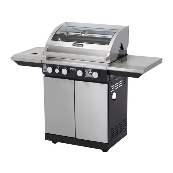
- Page 1 Matrix Gas Grill Model No. GM172-124 Model No. GM172-125 FOR OUTDOOR USE ONLY - OPERATES ON LPG Retain these instructions for future use Important: The installer or seller must leave these instructions with the consumer 4500-06/16...
-
Page 2: General Information
GENERAL INFORMATION Hose & Regulator Safety The regulator and hose assembly supplied with IMPORTANT the barbecue are suitable for LPG only. Hose connection thread is G1/4-19. Read these instruction carefully prior to use. A gas regulator adjusted to have an outlet Familiarise yourself with the appliance before pressure of 2.75kPa is supplied for connection connecting it to it’s gas container. -
Page 3: For Your Safety
FOR YOUR SAFETY • This barbecue must not be used indoors. • Only use in well ventilated areas. Failure to comply with these instructions could • CARBON MONOXIDE HAZARD - USING THIS result in a fire or explosion which could cause APPLIANCE IN AN ENCLOSED SPACE MAY serious bodily injury, death or property damage. -
Page 4: Bbq Specifications
GENERAL INFORMATION General Assembly Location of your Barbecue Remove the barbecue and components from DO NOT use your barbecue in garages, porches, breezeways, sheds or other enclosed areas. Your the packing carton. Check against parts list and barbecue is to be used OUTDOORS. The barbecue lay components out within easy reach. - Page 5 4 BURNER EXPLODED DIAGRAM...
- Page 6 6 BURNER EXPLODED DIAGRAM...
-
Page 7: Burner Parts List
4 BURNER PARTS LIST 1. Body Assembly 2. Side Burner 3. Side Shelf 4. Base Panel 5. Left Side Panel Assembly Assembly 6. Right Side Panel 7. Back Panel 8. Front Beam 9. Door Assembly 10. Cabinet 2pcs Separation Panel 11. - Page 8 6 BURNER PARTS LIST 1. Body Assembly 2. Side Burner 3. Side Shelf 4. Base Panel 5. Left Side Panel Assembly Assembly 6. Right Side Panel 7. Back Panel 8. Front Beam 9. Door Assembly 10. Cabinet 2pcs Separation Panel 11.
- Page 9 4 BURNER & 6 BURNER BOLT PACK A. Cushion Rubber B. M6*15 Screw C. M4*8 Screw D. M4*12 Screw 2pcs 55pcs 11pcs 24pcs E. M6 Shoulder Screw F. M6 Flat Washer G. M6 Spring Washer H. M6 Nut 4pcs 24pcs 24pcs 4pcs ASSEMBLY INSTRUCTIONS...
- Page 10 STEP 2 Use M6 x 15mm screw (B) x 4 pcs to attach cabinet left side panel (5) and cabinet right side panel (6) to the base panel (4). STEP 3 Use M6 x 15mm screw (B) x 5 pcs to attach cabinet back panel (7).
- Page 11 STEP 4 Use M6 x 15mm screw (B) x 4 pcs to attach cabinet horizontal beam (8). Use M6 x 15mm screw (B) x 8 pcs to attach triangle (20) x 2 pcs. Note: Please DO NOT tighten the screws of this step now. Affix cushion rubbers (A) to cabinet horizontal beam.
- Page 12 STEP 6 Use M6 x 15mm screw (B) x 4 pcs to attach grease tray rail (12/13) on the top of the cabinet separation panel. STEP 7 Put the grease tray (1) on the top of the cabinet separation panel. Make sure the hole in the grease tray is in line with the hole in the separation panel.
- Page 13 STEP 8 Use M4 x 10mm screw (D) x 24 pcs to attach the door hinge (21) x 4 pcs to attach the hinge spacer (26) x 4 pcs to the cabinet door (9) x 2 pcs. Note: There are two adjustable screws on the door hinge, which can help you adjust the gap between the two doors.
- Page 14 STEP 9 Put the firebox assy. (1) on the top of the cart, open the hood and then use M6 x 15mm screw (B) x 4 pcs, M6 flat washer (F) x 4 pcs and M6 spring washer (G) x 4 pcs to fix the firebox assy.
- Page 15 STEP 11 Attach M6 shoulder screw (E) x 2 pcs, M6 nut (H) x 2 pcs, flat washer (F) x 2 pcs and spring washer (G) x 2 pcs to the side shelf brackets’ lower holes and then hang the foldable side shelf onto them.
- Page 16 STEP 13 Use M6 x 15 screw (B) x 4 pcs to attach the side burner assy. to the firebox. Then adjust the side burner fascia to align with the main fascia and tighten the screws. STEP 14 Use M4 x 8mm screw (C) x 3 pcs to fix the injector bracket to the side burner assy.
- Page 17 STEP 15 STEP 16 Attach the side burner body to the side burner Insert the fat cup into the fat cup box beneath the assy. and then insert the ignition wire into the end separation panel. Slide in fully to the end. of the ignition pin.
- Page 18 STEP 18 Open the cabinet door, and let the hose go through the cabinet side panel to connect to the cylinder. Note: 4 Burner Shown STEP 19 STEP 20 Attach the regulator to your gas cylinder. Turn on the gas cylinder ensuring that all of the controls on the BBQ are turned OFF at this point.
- Page 19 STEP 21 STEP 22a Use a solution of soapy water (dishwashing If the connection is leaking, bubbles will start to liquid and water is fine). Brush it on or use a grow in the soapy solution. If this happens shut spray bottle as shown in the drawing.
-
Page 20: General Assembly
GENERAL ASSEMBLY 8. Slowly open the gas cylinder valve all the way. Do not put excessive force on the valve at the full open position, to avoid damaging the valve. Connecting & Disconnecting to Gas Source 9. Light barbecue as per the instructions provided. Familiarise yourself with the general information LIGHTING PROCEDURE and safety guidelines located at the front of this... -
Page 21: Operation
OPERATION Burner Operation & Ignition System Check Problem Possible Reason Solution Valve on cylinder is closed Open valve on cylinder Burner will not Control knob is closed Turn knob to high when lighting ignite Electronic igniter is faulty Use a long barbecue match Check that the gas bottle is not empty and Burner has gone out re-ignite the burner... -
Page 22: Care And Maintenance
CARE & MAINTENANCE Care of Cooking Surface As with all appliances, proper care and maintenance will keep them in top operating Use and care of the cooking surface is important. condition and prolong their life. Your new gas Do not use pans on the cooking surface. Do not barbecue is no exception. -
Page 23: Safe Appliance Locations
The following figures are diagrammatic representations of outdoor areas. Rectangular areas have been used in these figures – the same principles apply to any other shaped area. ® Gasmate is a registered trademark of: Sitro Group Australia Pty Ltd www.gasmate.com.au Aber, Hamilton, N.Z. www.gasmate.co.nz...
Need help?
Do you have a question about the GM172-124 and is the answer not in the manual?
Questions and answers