
Related Manuals for Daikin EWAD E-SS Series


Summary of Contents for Daikin EWAD E-SS Series
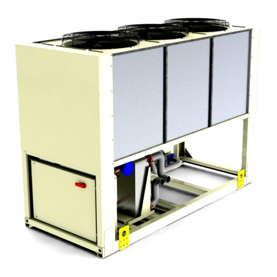
- Page 1 Installation, Operation and Maintenance Manual D-EIMAC00708-16EN Air-cooled single circuit screw chiller EWAD100 ÷ 410 E ERAD120 ÷ 490 E- (condensing unit) 50 Hz - Refrigerant R134a Original Instructions...
- Page 2 This Manual is a technical aid and does not represent a binding offer for Daikin. Daikin has drawn up this Manual to the best of its knowledge. The content cannot be held as explicitly or implicitly guaranteed as complete, precise or reliable.
-
Page 3: Table Of Contents
Index General Information ................................6 Receiving the machine ..............................6 Checks ....................................6 Purpose of this Manual ..............................6 Nomenclature ................................... 7 Operating limits ................................. 17 Storing .................................... 17 Operation ..................................17 Mechanical Installation ..............................19 Shipping ..................................19 Responsibility ................................. 19 Safety.................................... - Page 4 Oil filter replacement............................... 66 Oil filter replacement procedure ............................. 66 Refrigerant charge ................................67 Refrigerant replenishment procedure ..........................68 Standard Checks ................................69 Temperature and pressure transducers ......................... 69 Test sheet ................................... 70 Fluid side measurements ............................... 70 Refrigerant side measurements ............................. 70 Electrical measurements ..............................
- Page 5 Figure 17 - Installation of long power supply wires ......................38 Figure 18 - User connection to the interface M3 terminal boards ..................43 Figure 19 - EWAD E SS/SL - Not economised refrigerante circuit ..................46 Figure 20 - EWAD E SS/SL - Economised refrigerante circuit ..................47 Figure 21 –ERAD E SS/SL - Not economised refrigerante circuit ..................
-
Page 6: General Information
General Information ATTENTION The units described in the present manual represent a high value investment, maximum care should be taken to ensure correct installation and appropriate working conditions. Installation and maintenance must be performed by qualified and specifically trained personnel only. Correct maintenance of the unit is indispensable for its safety and reliability. -
Page 7: Nomenclature
Nomenclature E W A D 9 10 11 12 13 14 Machine type = Air-cooled chiller, cooling only = Air-cooled chiller, heat pump = Remote condenser chiller = Air cooled condensing unit EWW = Water-cooled chiller, cooling only = Air-cooled chiller, cooling only with centrifugal fan = Air-cooled chiller, cooling only with heat recovery Refrigerant = R-134a... -
Page 8: Table 1 - Ewad 100E÷180E -Ss - Hfc 134A - Technical Data
Table 1 – EWAD 100E ÷ 180E-SS - HFC 134a - Technical Data Unit SIze Capacity (1) Cooling Type Stepless Capacity control Minimum capacity Unit power input (1) Cooling 38.7 46.9 53.4 60.3 68.5 EER (1) 2.61 2.57 2.58 2.70 2.67 ESEER 2.93... -
Page 9: Table 2 - Ewad 210E÷410E-Ss - Hfc 134A - Technical Data
Table 2 - EWAD 210E ÷ 410E-SS - HFC 134a - Technical Data Unit SIze Capacity (1) Cooling Type Stepless Capacity control Minimum capacity Unit power input (1) Cooling 71.7 86.7 EER (1) 2.98 2.95 2.77 2.71 2.84 ESEER 3.02 3.18 3.05 3.23... -
Page 10: Table 3 - Ewad 100E÷180E-Sl - Hfc 134A - Technical Data
Table 3 – EWAD 100E ÷ 180E-SL – HFC134a - Technical Data Units Size Capacity (1) Cooling 97.9 Type Stepless Capacity control Minimum capacity Unit power input (1) Cooling 38.8 47.9 53.0 60.6 67.8 EER (1) 2.52 2.42 2.53 2.60 2.61 ESEER 3.01... -
Page 11: Table 4 - Ewad 210E÷400E-Sl - Hfc 134A - Technical Data
Table 4 – EWAD 210E ÷ 400E-SL - HFC 134a - Technical Data Units Size Capacity (1) Cooling Type Stepless Capacity control Minimum capacity Unit power input (1) Cooling 72.1 84.5 EER (1) 2.89 2.95 2.69 2.58 2.65 ESEER 3.32 3.55 3.41 3.34... -
Page 12: Table 5 - Erad 120E÷220E-Ss - Hfc 134A - Technical Data
Table 5 – ERAD 120E ÷ 220E-SS - HFC 134a - Technical Data Units Size Capacity (1) Cooling Type Stepless Capacity control Minimum capacity Unit power input (1) Cooling 41.8 51.0 57.4 65.2 73.7 EER (1) 2.90 2.83 2.87 3.00 2.97 Colour Ivory White... -
Page 13: Table 6 - Erad 250E÷490E-Ss - Hfc 134A - Technical Data
Table 6 – ERAD 250E ÷ 490E-SS - HFC 134a - Technical Data Units Size Capacity (1) Cooling Type Stepless Capacity control Minimum capacity Unit power input (1) Cooling 76.6 92.8 EER (1) 3.28 3.30 3.04 2.96 3.03 Colour Ivory White Casing Material Galvanized and painted steel sheet... -
Page 14: Table 7 - Erad 120E÷210E-Sl - Hfc 134A - Technical Data
Table 7 – ERAD 120E ÷ 210E-SL - HFC 134a - Technical Data Units Size Capacity (1) Cooling Type Stepless Capacity control Minimum capacity Unit power input (1) Cooling 42.3 52.5 57.6 66.3 73.9 EER (1) 2.74 2.61 2.75 2.82 2.83 Colour Ivory White... -
Page 15: Table 8 - Erad 240E÷460E-Sl - Hfc 134A - Technical Data
Table 8 – ERAD 240E ÷ 460E-SL - HFC 134a - Technical Data Units Size Capacity (1) Cooling Type Stepless Capacity control Minimum capacity Unit power input (1) Cooling 78.2 91.5 122.4 150.1 167.2 EER (1) 3.11 3.23 2.88 2.73 2.76 Colour Ivory White... -
Page 16: Table 9 - Sound Levels Ewad E-Ss - Erad E-Ss
Table 9 - Sound levels EWAD E-SS – ERAD E-SS Unit Unit Sound pressure level at 1 m from the unit in semispheric free field (rif. 2 x 10 Power size size 1000 2000 4000 8000 63 Hz 125 Hz 250 Hz 500 Hz dB(A) -
Page 17: Operating Limits
Operating limits Storing The environment conditions have to be in the following limits: Minimum ambient temperature -20°C Maximum ambient temperature 57°C Maximum R.H. 95% not condensing ATTENTION Storing below the minimum temperature above mentioned may cause damage to components such as the electronic controller and its LCD display. -
Page 18: Figure 2 - Operating Limits - Ewad E-Ss/Sl
Figure 2 - Operating limits – EWAD E-SS/SL COMP FULL LOAD ONLY Above this line (ICE Mode) Speed Operation with Modulation required Glycol (below 18°C Amb. (below 4°C Evap Temp for less than LWT) 3 fans units, below 10°C for 3 or more fans units) Evap Leaving Water Temperature (°C) Speedtroll required... -
Page 19: Mechanical Installation
Mechanical Installation Shipping The stability of the machine during shipping must be ensured. If the machine is shipped with a wooden cross -plank on its base, this cross-plank must only be removed after the final destination has been reached. Responsibility The manufacturer declines all present and future responsibility for any damage to persons, animals or things caused by negligence of operators failing to follow the installation and maintenance instructions in this Manual. -
Page 20: Moving And Lifting
Moving and lifting Avoid bumping and/or jolting during unloading from the lorry and moving the machine. Do not push or pull the machine from any part other than the base frame. Block the machine from sliding inside the lorry in order to prevent damage to the panels and to the base frame. -
Page 21: Minimum Space Requirements
When two or more machines are positioned side by side, a distance of at least 3600 mm between condenser batteries is recommended. For further solutions, please consult Daikin technicians. D–EIMAC00708-16EN - 21/76... -
Page 22: Sound Protection
THE WIDTH OF THE UNIT CAN BE DIFFERENT BUT THE MINIMUM RECOMMENDED INSTALLATION DISTANCES REMAIN THE SAME Figure 6 - Minimum recommended installation distances Sound protection When sound levels require special control, great care must be exercised in isolating the machine from its base, by appropriately applying antivibration devices (supplied optionally). -
Page 23: Water Treatment
In the event that glycol is added to the hydraulic system as anti-freeze protection, pay attention to the fact that intake pressure will be lower, the machine’s performance will be lower and water pressure drops will be greater. All machine - protection methods, such as anti-freeze, and low-pressure protection will need to be reset. -
Page 24: Evaporator And Recovery Exchangers Anti-Freeze Protection
Table 11 - Acceptable water quality limits 200 PH (25°C) 6,88,0 Total Hardness (mg CaCO / l) Electrical conductivity S/cm (25°C) 800 1.0 Iron (mg Fe / l) 200 Chloride ion (mg Cl / l) Sulphide ion (mg S / l) Nessuno 200... -
Page 25: Hydronic Kit (Optional)
Hydronic kit (optional) The optional hydronic kit foreseen for this series of machines (except CU Model) can be composed of a single in-line pump or a twin in-line pump. According to the choice made when ordering the machine, the kit could be configured as in the following figure. -
Page 26: Figure 11 - Ewad E Ss/Sl - Available External Lift For Water Pumps Kit (Option On Request) - Low Lift Single Pump
Figure 11 – EWAD E SS/SL - Available external lift for water pumps kit (option on request) - Low lift single pump Water flow rate (l/s) Figure 12 – EWAD E-SS/SL - Available external lift for water pumps kit (option on request) - High lift single pump Water flow rate (l/s) A. -
Page 27: Figure 13 - Ewad E Ss/Sl - Available External Lift For Water Pumps Kit (Option On Request) - Low Lift Twin Pump
Figure 13 – EWAD E-SS/SL - Available external lift for water pumps kit (option on request) - Low lift twin pump Water flow rate (l/s) Figure 14 – EWAD E-SS/SL - Available external lift for water pumps kit (option on request) - High lift twin pump Water flow rate (l/s) A. -
Page 28: Refrigerating Circuit Safety Valves
Refrigerating circuit safety valves Each system comes with safety valves that are installed on each circuit, both on the evaporator and on the condenser. The purpose of the valves is to discharge the refrigerant inside the refrigerating circuit in the event of any malfunction. WARNING This unit is designed for installation outdoors. -
Page 29: Figure 16 - Heat Recovery Pressure Drop - Ewad E Ss/Sl
Figure 16 - Heat recovery pressure drop – EWAD E-SS/SL Water flow rate (l/s) S. EWAD100E-SS / SL X. EWAD210E-SS / SL EWAD120E-SS / SL Y. EWAD260E-SS / EWAD250E-SL U. EWAD140E-SS / EWAD130E-SL EWAD310E-SS / EWAD300E-SL V. EWAD160E-SS / SL Å. -
Page 30: Guidelines Forerad E- Installation
Daikin for wrong design of piping coming from the use of tables. Table 12 - Recomandend maximum equivalent length (m) for Suction line... -
Page 31: Expansion Valve
To assure oil return to the compressor also at partial load do not use suction piping in the upward direction with size above 2” 1/4" for full load cooling capacity in the range 100-150 kW; above 2” 5/8 for full load cooling capacity in the range 150-200 kW, above 3”... -
Page 32: Installation Of Evaporator Fluid Sensors
Installation of evaporator fluid sensors Two temperature sensors are supplied, cabled to the unit controller, with a cable length of 10 m. They have to be installed to measure the chilles fluid at the inlet (WIE) and at the outlet (WOE) of the evaporator, and the are used by the unit controller to adjust the unit capacity to the demand. -
Page 33: Electrical Installation
Electrical installation General specifications CAUTION All electrical connections to the machine must be carried out in compliance with laws and regulations in force. All installation, management and maintenance activities must be carried out by qualified personnel. Refer to the specific wiring diagram for the machine that you have purchased and which was sent with the unit. Should the wiring diagram not appear on the machine or should it have been lost, please contact your nearest manufacturer office, who will send you a copy. -
Page 34: Table 15 - Electrical Data Ewad 100E÷180E -Ss
Table 15 - Electrical Data EWAD 100E ÷ 180E-SS Unit Size Phase Frequency Power Supply Voltage Minimum -10% -10% -10% -10% -10% Voltage Tolerance Maximum +10% +10% +10% +10% +10% Maximum starting current Nominal running current cooling Unit Maximum running current Maximum current for wires sizing Fans Nominal running current in cooling... -
Page 35: Table 17 - Electrical Data Ewad 100E÷180E-Sl
Table 17 - Electrical Data EWAD 100E ÷ 180E SL Unit Size Phase Frequency Power Supply Voltage Minimum -10% -10% -10% -10% -10% Voltage Tolerance Maximum +10% +10% +10% +10% +10% Maximum starting current Nominal running current cooling Unit Maximum running current Maximum current for wires sizing Fans Nominal running current in cooling... -
Page 36: Table 19 - Electrical Data Erad 120E÷220E-Ss
Table 19 - Electrical Data ERAD 120E ÷ 220E-SS Unit Size Phase Frequency Power Supply Voltage Minimum -10% -10% -10% -10% -10% Voltage Tolerance Maximum +10% +10% +10% +10% +10% Maximum starting current Nominal running current cooling Unit Maximum running current Maximum current for wires sizing Fans Nominal running current in cooling... -
Page 37: Table 21 - Electrical Data Erad 120E÷210E-Sl
Table 21 - Electrical Data ERAD 120E ÷ 210E-SL Unit Size Phase Frequency Power Supply Voltage Minimum -10% -10% -10% -10% -10% Voltage Tolerance Maximum +10% +10% +10% +10% +10% Maximum starting current Nominal running current cooling Unit Maximum running current Maximum current for wires sizing Fans Nominal running current in cooling... -
Page 38: Electrical Components
Electrical components All power and interface electrical connections are specified in the wiring diagram that is shipped with the machine. The installer must supply the following components: Power supply cables (dedicated conduit) Interconnection and interface cables (dedicated conduit) Suitable line protection devices (fuses or circuit breakers, please see electrical data). Power Circuit Wiring A disconnect switch is factory-installed for isolating electrically the unit when switched off. - Page 39 EWAD 100E ÷ 400E-SL Model EWAD 100E-SL EWAD 120E-SL EWAD 130E-SL EWAD 160E-SS EWAD 180E-SL Disconnect Switch Size 400 A 400 A 400 A 400 A 400 A Short circuit rating (note 1) 25 kA 25 kA 25 kA 25 kA 25 kA Recommended Fuses 125 A gG...
-
Page 40: Electrical Heaters
ERAD 120E ÷460E-SL Model ERAD 120E-SL ERAD 140E-SL ERAD 160E-SL ERAD 190E-SL ERAD 210E-SL Disconnect Switch Size 400 A 400 A 400 A 400 A 400 A Short circuit rating (note 1) 25 kA 25 kA 25 kA 25 kA 25 kA Recommended Fuses 125 A gG... -
Page 41: Water Pump Control
Table 24 - Electrical data for optional pumps Unit model Engine power Engine current (KW) requirement (A) Low head High head Low head High head EWAD 100E ÷140E-SS EWAD 100E ÷130E-SL EWAD 160E ÷ 210E-SS EWAD 160E ÷ 210E-SL ST/LN EWAD 260E-SS 10.1 EWAD 250E-SL... -
Page 42: Unit Limitation - Electrical Wiring (Optional)
The signal wire must be directly connected to terminals 886 and 887 of the terminal board MC24. A shielded wire is recommended and it must not be laid in proximity of the power cables, so as not to induce interference with the electronic controller. -
Page 43: Figure 18 - User Connection To The Interface M3 Terminal Boards
Figure 18 – Field Wiring Diagram D–EIMAC00708-16EN - 43/76... -
Page 44: Operation
Operation Operator’s responsibilities It is important that the operator is appropriately trained and becomes familiar with the apparatus before operating the machine. In addition to reading this manual, the operator must study the microprocessor operating manual and the wiring diagram in order to understand startup sequence, operation, shutdown sequence and operation of all the safety devices. During the machine’s initial startup phase, a technician authorized by the manufacturer is available to answer any questions and to give instructions as to the correct operating procedures. - Page 45 In economised units, before expansion, a portion of liquid is spilled from the soobcooled condensate, expanded to an intermediate pressure and than flows trough an heat exchanger where, on the other side, flows t he remaining part of liquid. In this way the soobcooling on the liquid is increased and a small amount of vapour at intermediate value is produced and injected in the compressor economiser port, so increasing compressor efficiency (reducing discharge superheat).
-
Page 46: Figure 19 - Ewad E Ss/Sl - Not Economised Refrigerante Circuit
Figure 19 – EWAD 100E ÷ 410E SS – EWAD 100E ÷ 400E SL Not economised refrigerant circuit Single-screw compressor Low-pressure safety valve (15,5 bar) Non-return valve Compressor suction shutoff valve Compressor discharge shutoff valve Service port High-pressure safety valve (25,5 bar) Water outlet connection Condenser coil Water inlet connection... -
Page 47: Figure 20 - Ewad E Ss/Sl - Economised Refrigerante Circuit
Figure 20 - EWAD 100E ÷ 410E SS – EWAD 100E ÷ 400E SL Economised refrigerante circuit Single-screw compressor Service port Non-return valve Water outlet connection Compressor discharge shutoff valve Water inlet connection High-pressure safety valve (25,5 bar) Economiser Condenser coil Economiser solenoid valve Built-in undercooling section Economiser thermostatic expansion valve... -
Page 48: Erad E-Ss/Sl
ERAD E-SS/SL ERAD E-SS/SL units (Condensing Units) refrigerant cycle is identical to EWAD E-SS/SL refrigerant cycle except they are without evaporator, expansoion valve and low pressure safety valve. Units are designed to be used with external evaporator either for chilling water or air. Typical, but not exhaustive, use is for custom-made evaporator for process cooling and air-handling unit application. -
Page 49: Figure 22 -Erad E Ss/Sl - Economised Refrigerante Circuit
Figure 22 - ERAD 120E ÷ 490E-SS – ERAD 120E ÷ 460E-SL Economised refrigerante circuit Single-screw compressor Suction line connection Non-return valve Liquid line connection Compressor discharge shutoff valve Economiser High-pressure safety valve (25,5 bar) Economiser solenoid valve Condenser coil Economiser thermostatic expansion valve Built-in undercooling section Low-pressure transducer (-0,5:7,0 bar) -
Page 50: Description Of The Chilling Cycle With Heat Recovery
Description of the chilling cycle with heat recovery With reference to stardard refrigerante cycle (both for chiller and condensing units), the high pressure refrigerant that has been separated from the oil, before reaching the condenser coil, flows trough the recovery heat eexchanger, where it dissipates the heat (from gas de-superheating and partial condensation) , warming the water which travels through the exchanger. -
Page 51: Figure 23 - Ewad E Ss/Sl - Heat Recovery Refrigerante Circuit - Not Economised Units
Figure 23 - EWAD 100E ÷ 410E SS – EWAD 100E ÷ 400E SL Heat recovery refrigerante circuit – Not Economised units Single-screw compressor Water inlet connection Non-return valve Additional Subcooler Compressor discharge shutoff valve Additional Subcooler solenoid valve High-pressure safety valve (25,5 bar) Additional subcooler thermostatic expansion valve Condenser coil Heat recovery exchanger... -
Page 52: Figure 24 - Ewad E Ss/Sl - Heat Recovery Refrigerante Circuit - Economised Units
Figure 24 - EWAD 100E ÷ 410E SS – EWAD 100E ÷ 400E SL Heat recovery refrigerante circuit - Economised units Single-screw compressor Water inlet connection Non-return valve Economiser Compressor discharge shutoff valve Economiser solenoid valve High-pressure safety valve (25,5 bar) Economiser thermostatic expansion valve Condenser coil Heat recovery exchanger... -
Page 53: Figure 25 -Ewad E Ss/Sl - Heat Recovery Refrigerante Circuit - Not Economised Units
Figure 25 - ERAD 120E ÷ 490E-SS – ERAD 120E ÷ 460E-SL Heat recovery refrigerante circuit - Not Economised units Single-screw compressor Additional Subcooler Non-return valve Additional Subcooler solenoid valve Compressor discharge shutoff valve Additional subcooler thermostatic expansion valve High-pressure safety valve (25,5 bar) Heat recovery exchanger Condenser coil Heat recovery water inlet... -
Page 54: Figure 26 -Erad E Ss/Sl - Heat Recovery Refrigerante Circuit - Economised Units
Figure 26 - ERAD 120E ÷ 490E-SS – ERAD 120E ÷ 460E-SL Heat recovery refrigerante circuit - Economised units Single-screw compressor Economiser Non-return valve Economiser solenoid valve Compressor discharge shutoff valve Economiser thermostatic expansion valve High-pressure safety valve (25,5 bar) Heat recovery exchanger Condenser coil Heat recovery water inlet... -
Page 55: Compressor
Compressor The single-screw compressor is of the semi-hermetic type with asynchronous three-phase two-pole engine which is directly splined to the main shaft. The intake gas from the evaporator cools the electrical engine before entering the intake ports. Inside the electrical engine, there are temperature sensors completely covered by the coil winding that constantly monitor engine temperature. -
Page 56: Figure 29 - Compression Process
1. and 2. Suction Main rotor flutes 'a', 'b' and 'c' are in communication at one end with the suction chamber via the bevelled rotor end face, and are sealed at the other end by the star rotor teeth. As the main rotor turns, the effective length flutes increases... -
Page 57: Cooling Capacity Control
Cooling capacity control The compressors are factory-equipped with a stepless cooling capacity control system. Unloading slides reduces the groove’s intake capacity and reduces its actual length. Unloading slides are controlled by the pressure of the oil coming from the separator or drained towards the compressor suction;... -
Page 58: Pre-Startup Checks
Pre-startup checks General Once the machine has been installed, use the following procedure to check that is has been done properly: ATTENTION Switch off the power supply of the machine before performing any checks. Failure to respect these rules at this stage can result in serious injury to the operator or even death. Inspect all the electrical connections to the power circuits and to the compressors including the contactors , fuse carriers and electrical terminals and check that they are clean and well secured. -
Page 59: Units With An External Water Pump
IMPORTANT Before placing the machine into operation, clean the hydraulic circuit. Dirt, incrustation, corrosion residue and other extraneous material can accumulate in the heat exchanger and reduce its thermal exchange capacity. Pressure drops can also increase, consequently reducing water flow. Thus, correct water treatment reduces the risk of corrosion, erosion, scaling, etc. -
Page 60: Electrical Heater Power Supply
100 _____ Unbalance %: AVG = Average Example: the three phases measure respectively 383, 386 and 392 Volts, the average is: 383+386+392 387 Volts thus the unbalance percentage is below the maximum allowed (3%) Electrical heater power supply Each compressor comes with an electrical heater located at the bottom of the compressor. -
Page 61: Startup Procedure
Startup procedure Turning on the machine With the general switch Q10 closed, check that switches Q0, Q1 and Q12 are in the Off (or 0) positione. Close the thermal-magnetic switch Q12 and wait for the microprocessor and the control to start. Check that the oil temperature is warm enough. -
Page 62: Seasonal Shutdown
IMPORTANT If the machine is not supplied with an onboard built-in pump, do not shut down the external pump before 3 minutes have elapsed after the last compressor has shut down. Early shutdown of the pump triggers a water-flow failure alarm. Seasonal shutdown Turn switch Q1 to the Off (or 0) position to shut down the compressors, using the normal pumpdown procedure. -
Page 63: System Maintenance
System maintenance WARNING All routine and extraordinary maintenance activities on the machine must be carried out solely by qualified personnel who is personally familiar with the apparatus, with its functioning, with the correct servicing procedures and who know all the safety requirements and are aware of the dangers. -
Page 64: Lubrication
Lubrication McEnergy units do not require a routine procedure for lubrication of components. The venti lator bearings have permanent lubrication and no additional lubrication is therefore required. Compressor oil is of the synthetic type and is highly hygroscopic. It is therefore advised to limit its exposition to the atmosphere during the storage and loading phases. -
Page 65: Routine Maintenance
Routine maintenance Table 26 - Routine maintenance programme List of Activities Weekly Monthly Yearly (Note 1) (Note 2) General: Collection of operating data (Note 3) Visual inspection of machine for any damage and/or loosening Verification of thermal insulation integrity Clean and paint where necessary Analysis of water (6) Electrical: Verification of control sequence... -
Page 66: Oil Filter Replacement
Shut down the relevant compressor by turning the Q1 or Q2 switch to Off Wait until the compressor has stopped and close the tap located on the liquid line Start the relevant compressor by turning the Q1 or Q2 switch to On. Check the relevant evaporation pressure on the microprocessor display. -
Page 67: Refrigerant Charge
Connect the recuperator to the compressor and recover the refrigerant in a suitable and clean storage container. Evacuate the refrigerant until the internal pressure has turned negative (compared to atmospheric pressure). The amount of refrigerant dissolved in the oil is reduced to a minimum in this way. Remove the oil in the compressor by opening the discharge valve located under the motor Remove the oil filter cover and remove the internal filtering element. -
Page 68: Refrigerant Replenishment Procedure
If the refrigerant level is slightly low, the passage of bubbles can be seen through the liquid pilot lamp. Replenish the circuit as described in the replenishment procedure. If the gas level in the machine is moderately low, the corresponding circuit could have some low -pressure stops. Replenish the corresponding circuit as described in the replenishment procedure. -
Page 69: Standard Checks
Standard Checks Temperature and Pressure Transducers The unit comes factory-equipped with all the sensors listed below. Periodically check that their measurements are correct by means of sample instruments (manometers, thermometers); correct readings if necessary using the microprocessor keyboard. Well-calibrated sensors ensure better efficiency for the machine and a longer lifetime. Note: refer to the microprocessor use and maintenance manual for a complete description of applications, setting and adjustments. -
Page 70: Test Sheet
Test sheet It is recommended that the following operation data are noted periodically in order to check that the machine is functioning properly over time. These data will also be extremely useful to the technicians who will be performing routine and/or extraordinary maintenance on the machine. -
Page 71: Service And Limited Warranty
Service and limited warranty All machines are factory-tested and guaranteed for 12 months as of the first startup or 18 months as of delivery. These machines have been developed and constructed according to high quality standards ensuring years of failure -free operation. - Page 72 Factory and Field charged units instructions (Important information regarding the refrigerant used) The refrigerant system will be charged with fluorinated greenhouse gases. Do not vent gases into the atmosphere. 1 Fill in with indelible ink the refrigerant charge label supplied with the product as following instructions: the refrigerant charge for each circuit (1;...
- Page 73 Field charged units instructions (Important information regarding the refrigerant used) The refrigerant system will be charged with fluorinated greenhouse gases. Do not vent gases into the atmosphere. 1 Fill in with indelible ink the refrigerant charge label supplied with the product as following instructions: the refrigerant charge for each circuit (1;...
- Page 74 Disposal The unit is made of metal and plastic parts. All these parts must be disposed of in accordance with the local regulations in terms of disposal. Lead batteries must be collected and taken to specific refuse collection centres. D–EIMAC00708-16EN - 74/76...
- Page 75 D–EIMAC00708-16EN - 75/76...
- Page 76 The present publication is drawn up by of information only and does not constitute an offer binding upon Daikin Applied Europe S.p.A.. Daikin Applied Europe S.p.A. has compiled the content of this publication to the best of its knowledge. No express or implied warranty is given for the completeness, accuracy, reliability or fitness for particular purpose of its content, and the products and services presented therein.
Need help?
Do you have a question about the EWAD E-SS Series and is the answer not in the manual?
Questions and answers