Sign In
Upload
Download
Table of Contents
Contents
Add to my manuals
Delete from my manuals
Share
URL of this page:
HTML Link:
Bookmark this page
Add
Manual will be automatically added to "My Manuals"
Print this page
×
Bookmark added
×
Added to my manuals
Manuals
Brands
Daikin Manuals
Chiller
EWAQ016CAW
Installation and operation manual
Daikin EWAQ016CAW Installation And Operation Manual
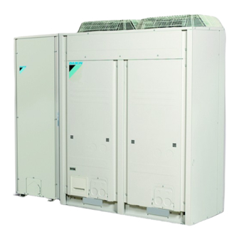
Packaged air-cooled water chiller
Hide thumbs
1
2
3
Table Of Contents
4
5
6
7
8
9
10
11
12
13
14
15
16
17
18
19
20
21
22
23
24
25
26
27
28
29
30
31
32
33
34
35
36
37
38
39
40
page
of
40
Go
/
40
Contents
Table of Contents
Troubleshooting
Bookmarks
Table of Contents
1 About the Documentation
Table of Contents
About this Document
For the Installer
2 About the Box
Outdoor Unit
To Remove the Accessories from the Outdoor Unit
3 About the Units and Options
About the Outdoor Unit
System Layout
4 Preparation
Preparing Installation Site
Installation Site Requirements of the Outdoor Unit
Preparing Water Piping
Water Circuit Requirements
Formula to Calculate the Expansion Vessel Pre-Pressure
To Check the Water Volume and Expansion Vessel Pre-Pressure
Changing the Pre-Pressure of the Expansion Vessel
To Check the Water Volume: Examples
Preparing Electrical Wiring
Safety Device Requirements
5 Installation
Opening the Units
To Open the Outdoor Unit
To Open the Electrical Component Box of the Outdoor Unit
Mounting the Outdoor Unit
To Provide the Installation Structure
Connecting the Water Piping
Precautions When Connecting the Water Piping
To Fill the Water Circuit
To Protect the Water Circuit against Freezing
To Insulate the Water Piping
Connecting the Electrical Wiring
Field Wiring: Overview
To Route and Fix the Power Supply
To Install the Main Switch Handle
To Connect the Power Supply and Transmission Cables
To Install the Remote Controller
To Install Optional Equipment
6 Configuration
Overview: Configuration
Making Field Settings
About Making Field Settings
Field Setting Components
To Access the Field Setting Components
To Access Mode 1 or 2
To Use Mode 1
To Use Mode 2
Mode 1: Monitoring Settings
Mode 2: Field Settings
Field Settings on the Remote Controller
Switching between Cooling and Heating
7 Commissioning
Precautions When Commissioning
Checklist before Commissioning
Final Check
8 Troubleshooting
Error Codes: Overview
9 Technical Data
Service Space: Outdoor Unit
Piping Diagram: Outdoor Module
Wiring Diagram: Outdoor Unit
For the User
10 About the System
System Layout
11 User Interface
12 Operation
Operation Range
Quick Start-Up
Operating the System
About the Clock
About Operating the System
Space Cooling Operation
Space Heating Operation
Other Operation Modes
Schedule Timer
Operating the Optional Demand PCB
Operating the Optional External Control Adapter
Operating the Optional Remote Controller
13 Maintenance and Service
About the Refrigerant
After-Sales Service and Warranty
Warranty Period
Recommended Maintenance and Inspection
14 Troubleshooting
Error Codes: Overview
15 Relocation
16 Disposal
Ewaq016~064Caw + Ewyq016~064Caw
Advertisement
Quick Links
1
Outdoor Unit
2
Error Codes: Overview
3
Error Codes: Overview
Download this manual
EWAQ016CAW
EWAQ021CAW
EWAQ025CAW
EWAQ032CAW
EWAQ040CAW
EWAQ050CAW
EWAQ064CAW
EWYQ016CAW
EWYQ021CAW
EWYQ025CAW
EWYQ032CAW
EWYQ040CAW
EWYQ050CAW
EWYQ064CAW
Installation and operation
Packaged air-cooled water chiller
manual
Installation and operation manual
Packaged air-cooled water chiller
English
Table of
Contents
Previous
Page
Next
Page
1
2
3
4
5
Advertisement
Table of Contents
Troubleshooting
Final check
22
Operating the optional remote controller
35
Need help?
Do you have a question about the EWAQ016CAW and is the answer not in the manual?
Ask a question
Questions and answers
Subscribe to Our Youtube Channel
Related Manuals for Daikin EWAQ016CAW
Chiller Daikin EWYQ007ACV3P Operation Manual
Packaged air-cooled water chillers and packaged reversible air to water heat pumps (12 pages)
Chiller Daikin EWAQ080DAYN Operation Manual
Packaged air-cooled water chillers (31 pages)
Chiller Daikin EWAQ006ADVP Operation Manual
Packaged air-cooled water chillers and packaged reversible air to water heat pumps (12 pages)
Chiller Daikin EWAQ005ADVP Operation Manual
Packaged air-cooled water chillers and packaged reversible air to water heat pumps (12 pages)
Chiller Daikin EWAQ007ADVP Operation Manual
Packaged air-cooled water chillers and packaged reversible air to water heat pumps (12 pages)
Chiller Daikin EWAQ~G-SS Installation, Operation And Maintenance Manual
Air cooled chiller multiscroll (22 pages)
Chiller Daikin EWAQ016BAW Installation And Operation Manual
Packaged air-cooled water chiller (48 pages)
Chiller Daikin EWAQ016BAW Service Manual
Small inverter chillers (229 pages)
Chiller Daikin EWAQ-E Installation, Operation And Maintenance Manual
Air cooled scroll chiller (209 pages)
Chiller Daikin EWAQ032CAW Installation And Operation Manual
Packaged air-cooled water chiller (40 pages)
Chiller Daikin EWAQ040CAW Installation And Operation Manual
Packaged air-cooled water chiller (40 pages)
Chiller Daikin EWAQ-E Series Installation, Operation And Maintenance Manual
(44 pages)
Chiller Daikin EWAQ009ACV3 Operation Manual
Packaged air-cooled water chillers and packaged reversible air to water heatpumps (16 pages)
Chiller Daikin EWWQ-G Operation Manual
Air and water cooled scroll chillers & heat pump (82 pages)
Chiller Daikin EWAQ005AAV3P Operation Manual
(12 pages)
Chiller Daikin EWAA011DAV3P User Reference Manual
Packaged air-cooled water chillers and packaged air to water heat pumps (56 pages)
This manual is also suitable for:
Ewaq021caw
Ewaq025caw
Ewaq050caw
Ewaq064caw
Ewyq016caw
Ewyq021caw
...
Show all
Ewyq025caw
Ewyq032caw
Ewyq040caw
Ewyq050caw
Ewyq064caw
Ewaq032caw
Ewaq040caw
Table of Contents
Print
Rename the bookmark
Delete bookmark?
Delete from my manuals?
Login
Sign In
OR
Sign in with Facebook
Sign in with Google
Upload manual
Upload from disk
Upload from URL


Need help?
Do you have a question about the EWAQ016CAW and is the answer not in the manual?
Questions and answers