Table of Contents
Advertisement
Quick Links
Advertisement
Table of Contents

Subscribe to Our Youtube Channel
Related Manuals for Daikin EWAD TB


Summary of Contents for Daikin EWAD TB
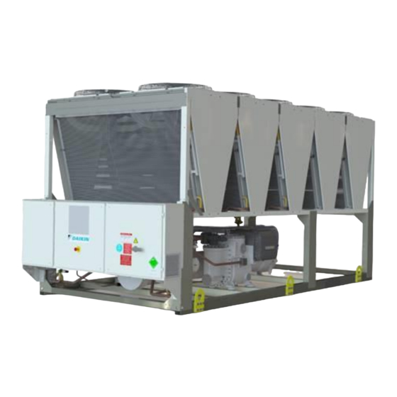
- Page 1 Rev. Date 01-2023 Supersedes D–EIMAC01502-18_02EN Installation, Operation and Maintenance Manual Installation, Operation and Maintenance Manual D–EIMAC01502-18_03EN Air cooled chiller with screw compressor EWAD~T~B EWAD~T~C Refrigerant: R-134a Original Version...
-
Page 2: Table Of Contents
Contents INTRODUCTION..............................5 Precautions against residual risks .......................... 5 Description ................................6 General Information ............................7 Receiving the unit ............................7 Operating limits ..............................8 Storing Storage ............................... 8 Operation ................................8 Mechanical Installation ..........................10 Safety ..................................10 5.1.1 Safety devices ............................. -
Page 3: Figure 1 - Typical Refrigerant Circuit (Dual Circuit)
Figure 1 - Typical refrigerant circuit (Dual Circuit) Water inlet and outlet are indicative. Please refer to the machine dimensional diagrams for exact water connections. D–EIMAC01502–18_03EN - 3/25... - Page 4 Optional Safety valves can be provided with a changeover device as optional Legend Compressor Heat Recovery (optional) Pressure relief valve Pset= 25,5 bar Microchannel condenser coil Angle valve Dryer filter Moisture indicator Economizer heat exchanger Solenoid valve Termostatic expansion valve Electronic expansion valve Evaporator (S&T) Pressure relief valve Pset= 15,5 bar...
-
Page 5: Introduction
INTRODUCTION This manual provides information on the standard functions and procedures of all units in the series and is an important supporting document for qualified personnel, but can never replace it. All units are delivered with wiring diagrams, certified drawings, nameplate; and DOC (Declaration Of Conformity);... -
Page 6: Description
25. keep all the safety devices in good working order and check them periodically according to the regulations in force 26. keep all lubricants in suitably marked containers 27. do not store inflammable liquids near the unit 28. solder or braze only empty pipes after removing all traces of lubricant oil; do not use flames or other heat sources close to pipes containing refrigerant fluid 29. -
Page 7: General Information
GENERAL INFORMATION All units are delivered with wiring diagrams, certified drawings, nameplate; and DOC (Declaration Of Conformity); these documents show all technical data for the unit you have bought and they MUST BE CONSIDERED ESSENTIAL DOCUMENTS OF THIS MANUAL In case of any discrepancy between this manual and the equipment’s documents please refer to on board documents. In case of any doubt contact the manufacturer representative. -
Page 8: Operating Limits
OPERATING LIMITS 4.1 Storing Storage Environmental conditions must be within the following limits: Minimum ambient temperature -20°C Maximum ambient temperature 57°C Maximum R.H. 95% not condensing Storing below the minimum temperature may cause damage to components. Storing above the maximum temperature causes opening of safety valves. -
Page 9: Figure 2 - Description Of The Labels Applied To The Electrical Panel
Figure 2 - Description of the labels applied to the electrical panel Double circuits unit Label Identification 1 – Manufacturer’s logo 5 – Cable tightening warning 2 – Gas type 6 – Non flammable gas symbol 3 – Hazardous Voltage warning 7 –... -
Page 10: Mechanical Installation
MECHANICAL INSTALLATION 5.1 Safety The unit must be firmly secured to the soil. It is essential to observe the following instructions: − The unit can only be lifted using the lifting points marked in yellow fixed to its base. − It is forbidden to access the electrical components without having opened the unit main switch and switched off the power supply. -
Page 11: Safety Devices
5.1.1 Safety devices In accordance with the Pressure Equipment Directive the following protection devices are used: High pressure switch → safety accessory. External relief valve (refrigerant side) → over pressure protection. External relief valve (heat transfer fluid side) → The selection of these relief valves must be made by the personnel responsible for completing the hydraulic circuit(s). - Page 12 Unit with 6 lifting points (The drawing shows only the 12 fans version. The lifting mode is the same for the different number of fans) Unit with 8 lifting points D–EIMAC01502–18_03EN - 12/25...
-
Page 13: Figure 4 - Unit Levelling
Figure 4 – Unit Levelling For installation on the ground, a strong concrete base, at least 250 mm thickness and wider than the unit must be provided. This base must be able to support the weight of the unit. The unit must be installed above antivibrating mounts (AVM), rubber or spring types. The unit frame must be perfectly levelled above the AVM. -
Page 14: Minimum Space Requirements
Figure 5 - Minimum clearance requirements d= 3000/4000 mm (according to evaporator dimensions) for dual/trial circuit units If h<Hc=2,4 m, minimum L=3,0 m; if h>Hc or L< 3,0 m contact your Daikin distributor to evaluate the various possible arrangements D–EIMAC01502–18_03EN - 14/25... -
Page 15: Figure 6 - Multiple Chiller Installation
All the above cases are even more sensitive in case of design conditions close to the limits of the unit operating envelope. NOTE: Daikin cannot be considered responsible in case of malfunctions generated by hot air recirculation or insufficient airflow as result of improper installation if the above recommendations are ignored. -
Page 16: Sound Protection
5.6 Sound protection When sound levels require special control, great care must be exercised to isolate the unit from its base by appropriately applying anti-vibration elements (supplied as an option). Flexible joints must be installed on the water connections, as well. 5.7 Water piping Piping must be designed with the lowest number of elbows and the lowest number of vertical changes of direction. -
Page 17: Water Treatment
12. In the event that glycol is added to the water system as anti-freeze protection, pay attention to the fact that suction pressure will be lower, the unit’s performance will be lower and water pressure drops will be greater. All unit-protection systems, such as anti-freeze, and low-pressure protection will need to be readjusted. -
Page 18: Figure 7 - Water Piping Connection For Evaporator (Opt.78-79-80-81)
This system in made by a water cooled heat exchanger located on the compressors discharge pipe and a dedicated management of condensing pressure. To guarantee compressor operation within its envelope, units with heat recovery cannot operate with water temperature of the heat recovery water lower than 25°C. -
Page 19: Electrical Installation
ELECTRICAL INSTALLATION 6.1 General specifications All electrical connections to the unit must be carried out in compliance with laws and regulations in force. All installation, management and maintenance activities must be carried out by qualified personnel. Refer to the specific wiring diagram for the unit you have bougth. Should the wiring diagram not be on the unit or should it have been lost, please contact your manufacturer representative, who will send you a copy. -
Page 20: Maintenance
MAINTENANCE 8.1 Routine maintenance This chiller must be maintained by qualified technicians. Before beginning any work on the system the personnel shall assure that all security precautions have been taken. Neglecting unit maintenance in these environments, could degrade all parts of the units (coils, compressors, frames, pipes, etc..) with negative effect on performances and functionality. -
Page 21: Unit Maintenance And Cleaning
In environments with a high concentration of air-borne particles, it might be necessary to clean the condenser bank more often. Replace the oil filter when the pressure drop across it reaches 2.0 bar. Check for any dissolved metals. 0,10 : No action TAN (Total Acid Number) : Between 0.10 and 0.19 : Replace anti-acid filters and re-check after 1000 running hours. -
Page 22: Microchannel Coil Maintenance
8.3 Microchannel Coil Maintenance Routine cleaning of coil surfaces is essential to maintain proper operation of the unit, avoid corrosion and rusting. Elimination of contamination and removal of harmful residues will greatly increase the life of the coil and extend the life o f the unit. -
Page 23: Important Information Regarding The Refrigerant Used
IMPORTANT INFORMATION REGARDING THE REFRIGERANT USED This product contains fluorinated greenhouse gases. Do not vent gases into the atmosphere. Refrigerant type: R134a GWP(1) value: 1430 (1)GWP = global warming potential The refrigerant quantity necessary is indicated on the unit name plate. Periodical inspections for refrigerant leaks may be required depending on European or local legislation. -
Page 24: Disposal
DISPOSAL The unit is made of metal, plastic and electronic parts. All of these components must be disposed of in accordance with local disposal laws and if in scope with the national laws implementing the Directive 2012/19/EU (RAEE). Lead batteries must be collected and sent to specific waste collection centers. Avoid the escape of refrigerant gases into the environment by using suitable pressure vessels and tools for transferring the fluids under pressure. - Page 25 The present publication is drawn up by of information only and does not constitute an offer binding upon Daikin Applied Europe S.p.A.. Daikin Applied Europe S.p.A. has compiled the content of this publication to the best of its knowledge. No express or implied warranty is given for the completeness, accuracy, reliability or fitness for particular purpose of its content, and the products and services presented therein.
Need help?
Do you have a question about the EWAD TB and is the answer not in the manual?
Questions and answers