Table of Contents
Advertisement
Quick Links
Advertisement
Table of Contents

Related Manuals for Daikin EWAH TZ D Series


Summary of Contents for Daikin EWAH TZ D Series
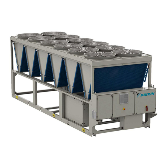
- Page 1 Date 05/2023 Supersedes Telepítés, használati és karbantartási útmutató Installation, Operation and Maintenance Manual D-EIMAC01905-23_00EN Air cooled chiller with inverter driven screw compressor EWAH~TZ~D EWAD~TZ~D EWAS~TZ~D EWFH~TZ~D EWFD~TZ~D EWFS~TZ~D Original Instructions...
-
Page 2: Table Of Contents
CONTENTS INTRODUCTION ..............................10 Precautions against residual risks ........................10 Description ................................11 Information about R1234ze(E) refrigerant ......................11 Information about installation ..........................12 RECEIVING THE UNIT ............................14 OPERATING LIMITS ............................15 Storage ................................. 15 Operation ................................15 Corrective factors ..............................22 MECHANICAL INSTALLATION .......................... - Page 3 LIST OF FIGURES Fig. 1- Refrigerant circuit diagram (P&ID) – MONO circuit units................... 4 Fig. 2 - Refrigerant circuit diagram (P&ID) – DUAL circuit units ................... 6 Fig. 3 – Hydronic Free cooling P&ID ............................. 8 Fig. 4. - Description of the labels applied to the electrical panel ................... 9 Fig.
-
Page 4: Fig. 1- Refrigerant Circuit Diagram (P&Id) - Mono Circuit Units
Fig. 1- Refrigerant circuit diagram (P&ID) – MONO circuit units D–EIMAC01905-23_00EN - 4/53... -
Page 5: Table 1 - Legend Refrigerant Circuit Diagram (P&Id) - Mono Circuit Units
Optional Safety valves can be provided with a changeover device as optional Table 1 – Legend refrigerant circuit diagram (P&ID) – MONO circuit units LEGEND DESCRIPTION SCREW COMPRESSOR HEAT EXCHANGER (BHPE) - HEAT RECOVERY OPTIONAL PRESSURE RELIEF VALVE Pset = 25,5 bar MICROCHANNEL CONDENSER COIL DISCHARGE SHUT OFF ANGLE VALVE DISCHARGE SHUT OFF BALL VALVE... -
Page 6: Fig. 2 - Refrigerant Circuit Diagram (P&Id) - Dual Circuit Units
Fig. 2 - Refrigerant circuit diagram (P&ID) – DUAL circuit units D–EIMAC01905-23_00EN - 6/53... -
Page 7: Table 2 - Legend Refrigerant Circuit Diagram (P&Id) - Dual Circuit Units
Optional Safety valves can be provided with a changeover device as optional Table 2 – Legend refrigerant circuit diagram (P&ID) – DUAL circuit units LEGEND DESCRIPTION SCREW COMPRESSOR HEAT EXCHANGER (BHPE) - HEAT RECOVERY OPTIONAL PRESSURE RELIEF VALVE Pset = 25,5 bar MICROCHANNEL CONDENSER COIL DISCHARGE SHUT OFF ANGLE VALVE DISCHARGE SHUT OFF BALL VALVE... -
Page 8: Fig. 3 - Hydronic Free Cooling P&Id
Fig. 3 – Hydronic Free cooling P&ID Table 3 – Legend hydronic Free cooling P&ID LEGEND DESCRIPTION ACCESS FITTING 1/4” NPT VALVE SAFETY VALVE 10 BAR 1/2” MF AIR VENT 3/8” NPT /TBC) DRAIN 1/4” NPT WATER FILTER TWO WAY VALVE MOTORIZED WATER FILTER FREECOOLING COIL WATER IN LINE... -
Page 9: Fig. 4. - Description Of The Labels Applied To The Electrical Panel
Table 4 – Units PS and TS REFRIGERANT PED/PER LINE PS [bar] TS [°C] GROUP R134a HIGH PRESSURE GAS 25.5 +10/+120°C R1234ze HIGH PRESSURE LIQ 25.5 -10/+80°C R513a LOW PRESSURE 15.5 -20/+80°C WATER CIRCUITS WATER IN/OUT -15/+55°C Fig. 4. - Description of the labels applied to the electrical panel Table 5 - Label Identification –... -
Page 10: Introduction
INTRODUCTION This manual is an important supporting document for qualified personnel, but it is not intended to replace such personnel. READ THIS MANUAL CAREFULLY BEFORE INSTALLING AND STARTING UP THE UNIT. IMPROPER INSTALLATION COULD RESULT IN ELECTRIC SHOCK, SHORT-CIRCUIT, LEAKS, FIRE OR OTHER DAMAGE TO THE EQUIPMENT OR INJURE TO PEOPLE. -
Page 11: Description
Due to this, no special precautions are required for storage, transport and handling. Daikin Applied Europe S.p.A. products comply with applicable European Directives and refer for unit design to product Standard EN378:2016 and industrial Standard ISO5149. Local authorities approval should be verified referring to European Standard EN378 and/or ISO 5149 (where R1234ze(E) is classified A2L –... -
Page 12: Information About Installation
Information about installation The chiller has to be installed in open air or machinery room (location classification III). To ensure location classification III a mechanical vent on the secondary circuit(s) has to be installed. Local building codes and safety standards shall be followed; in absence of local codes and standards refer to EN 378- 3:2016 as a guide. -
Page 13: Table 8 - R1234Ze(E) Lfl Value
o Mechanical ventilation shall be operated continuously or shall be switched on by the detector. • Detector shall automatically activate an alarm, start mechanical ventilation and stop the system when it triggers. • The location of detectors shall be chosen in relation to the refrigerant and they shall be located where the refrigerant from the leak will concentrate. -
Page 14: Receiving The Unit
Unit restitution is intended as ex-factory Daikin Applied Europe S.p.A. Daikin Applied Europe S.p.A. declines all responsibility for any damage that the machine may suffer during transport to the destination. Use extreme caution when handling the unit to prevent damage to components. -
Page 15: Operating Limits
OPERATING LIMITS Storage If the unit needs to be stored before installation, it is necessary to follow some precautions: Do not remove the protective plastic. Protect the unit from dust, bad weather and any rodents. Do not expose the unit to direct sunlight. Do not use heat sources and / or open flames near the machine. -
Page 16: Fig. 5 - Ewah-Tzd Blue Unit Envelope
Fig. 5 – EWAH-TZD Blue unit envelope Fig. 6 – EWAH-TZD Silver unit envelope D–EIMAC01905-23_00EN - 16/53... -
Page 17: Fig. 7 - Ewah-Tzd Gold And Platinum Unit Envelope
Fig. 7 – EWAH-TZD Gold and Platinum unit envelope EWAD-TZD Outside ambient air temperature ELWT Evaporator leaving water temperature Ref 1 Operation with ELWT < 4 °C requires Option 08 (brine) and glycol Ref 2 Operation with ELWT > 18 °C requires Option 187 (high evaporator leaving water temperature) Ref 3 Operation requires option 142 (High ambient temperature kit) Operation at outside ambient air temperature <... -
Page 18: Fig. 9 - Ewad-Tzd Silver Unit Envelope
Fig. 9 – EWAD-TZD Silver unit envelope Fig. 10 – EWAD-TZD Gold and Platinum unit envelope D–EIMAC01905-23_00EN - 18/53... -
Page 19: Fig. 11 - Ewas-Tzd Blue Unit Envelope
EWAS-TZD Outside ambient air temperature ELWT Evaporator leaving water temperature Ref 1 Operation with ELWT < 4 °C requires Option 08 (brine) and glycol Ref 2 Operation with ELWT > 18 °C requires Option 187 (high evaporator leaving water temperature) Ref 3 Operation requires option 142 (High ambient temperature kit) Operation at outside ambient air temperature <... -
Page 20: Fig. 12 - Ewas-Tzd Silver Unit Envelope
Fig. 12 – EWAS-TZD Silver unit envelope Fig. 13 – EWAS-TZD Gold and Platinum unit envelope D–EIMAC01905-23_00EN - 20/53... -
Page 21: Fig. 14 - Ewfh-Tzd Blue And Silver Unit Envelope
EWFH-TZD Outside ambient air temperature ELWT Evaporator leaving water temperature Ref 1 Operation with ELWT < 4 °C requires Option 08 (brine) and glycol Ref 2 Operation with ELWT > 18 °C requires Option 187 (high evaporator leaving water temperature) Ref 3 Operation requires option 142 (High ambient temperature kit) The charts shown in these pages constitute a guideline on operating limits in the range. -
Page 22: Corrective Factors
EWFD-TZD Outside ambient air temperature ELWT Evaporator leaving water temperature Ref 1 Operation with ELWT < 4 °C requires Option 08 (brine) and glycol Ref 2 Operation with ELWT > 18 °C requires Option 187 (high evaporator leaving water temperature) Ref 3 Operation requires option 142 (High ambient temperature kit) The charts shown in these pages constitute a guideline on operating limits in the range. -
Page 23: Table 10 - Altitude Correction Factor
Table 10 – Altitude correction factor 1200 1500 1800 1013 1.000 0.993 0.986 0.979 0.973 0.967 0.960 1.000 1.005 1.009 1.015 1.021 1.026 1.031 Legend: A = Altitude above sea level (m) B = Barometric pressure (mbar) C = Correction factor of the cooling capacity D = Correction factor of the absorbed power The maximum operating altitude is 2000 m above sea level. -
Page 24: Mechanical Installation
MECHANICAL INSTALLATION Safety The unit must be firmly secured to the soil. It is essential to observe the following instructions: − The unit can only be lifted using the lifting points marked in yellow fixed to its base. − It is forbidden to access the electrical components without having opened the unit main switch and switched off the power supply. -
Page 25: Handling And Lifting Instructions
All factory-installed relief valves are lead-sealed to prevent any calibration change. If the relief valves are installed on a changeover valve, this is equipped with a relief valve on both outlets. Only one of t he two relief valves is operating, the other one is isolated. Never leave the changeover valve in the intermediate position. If a relief valve is removed for checking or replacement please ensure that there is always an active relief valve on each of the changeover valves installed in the unit. - Page 26 Unit with 6 lifting points The drawing shows only the 10 fans version. The lifting mode is the same regardless of the number of fans. D–EIMAC01905-23_00EN - 26/53...
-
Page 27: Fig. 19 - Lifting Instructions
Unit with 8 lifting points The drawing shows only the 16 fans version. The lifting mode is the same regardless of the number of fans. Unit with 12 lifting points The drawing shows only the 24 fans version. The lifting mode is the same regardless of the number of fans. Fig. -
Page 28: Positioning And Assembly
Consult the dimensional drawing for the hydraulic and electrical connection of the units. The overall dimensions of the machine, as well as the weights described in this manual, are purely indicative. The contractual dimensional drawing and the related electrical scheme are delivered to the customer when ordering. -
Page 29: Fig. 21 - Minimum Clearance Requirements
1800 mm for single circuit units; d= 3000/3500 mm (according to evaporator dimensions) for dual circuit units . If h<Hc=2.4 m, minimum L=3.0 m; if h>Hc or L< 3.0 m Contact your Daikin distributor to evaluate the various possible arrangements. Fig. 21 - Minimum clearance requirements The above values are general guidelines. - Page 30 All the above cases are even more sensitive especially when design conditions are close to the limits of the unit operating envelope. NOTE: Daikin cannot be considered responsible in case of malfunctions generated by hot air recirculation or insufficient airflow as result of improper installation if the above recommendations are ignored.
-
Page 31: Noise And Sound Protection
Fig. 22. – Multiple Chiller Installation Noise and sound protection The unit is a source of noise mainly due to rotation of compressors and fans. The noise level for each model size is listed in sales documentation. If the unit is correctly installed, operated and maintained, the noise emission level do not require any special protection device to operate continuously close to the unit without any risk. -
Page 32: 4.6.2 Kit Pump Option
A suitable device that can maintain the water system under pressure (expansion tank, etc.). Water temperature and pressure indicators to assist the operator during service and maintenance. A filter or any device that can remove particles from the fluid. The use of a filter extends the life of the evaporator and pump and helps to keep the water system in a better condition. -
Page 33: 4.6.3 Flow Switch Option Installation
4.6.3 Flow switch option installation To ensure sufficient water flow through the evaporator, it is necessary to install a flowswitch on water circuit. The flow switch can be installed either on the inlet or outlet water piping. The purpose of the flow switch is to stop the unit in case of water flow interruption, thus protecting the evaporator from freezing. - Page 34 Once the free cooling function is enabled, the unit controller automatically manages the operation of the two valves. The system controls, also, fans operation in order to maximize the free cooling effect. System changeover is controlled by embedded unit controller, depending on operating conditions and unit setpoint. Between mechanical and freecooling operation the water side pressure drops are different, consequently the chiller water flow could be different.
-
Page 35: Fig. 25- Hydronic Free Cooling P&Id
The following figure reports a typical hydronic free cooling P&ID with the two motorized two-ways. Fig. 25– Hydronic Free cooling P&ID Table 14 - Legend hydronic Free cooling P&ID LEGEND DESCRIPTION ACCESS FITTING 1/4” NPT VALVE SAFETY VALVE 10 BAR 1/2” MF AIR VENT 3/8”... -
Page 36: Coolant Quality Requirements
Coolant quality requirements The minimum advised content of glycol is 25% (ethylene or propylenic). For operation at less than -10°C the percentage of glycol must be determined by the installer. The use of other substances different from ethylene or propylenic glycol shall be approved by the factory. -
Page 37: Free Cooling Purge Valve Related
Free cooling purge valve related The purge valves locate at four corners of the free cooling MCH are used for air purging and water purging. The below instruction is defined to protect the purge valve from deformation and/or failure. After dismounting the cap, please refer to the below to reinstall the cap: Check and clean the screw if there is dust and debris on screw’s surface Check the rubber o-ring in the cap and make sure that it is in the cap and in the right position Screw the purge valve with one circle by hand and make sure the screw match is well. -
Page 38: Electrical Installation
Provide an electrical circuit to connect the unit. It must be connected to the copper cables with an adequate section relativ e to the plate absorption values and according to the current electrical standards. Daikin Applied Europe S.p.A. declines all responsibility for an inadequate electrical connection. Connections to the terminals must be made with copper terminals and cables, otherwise overheating or corrosion may occur at the connection points with the risk of damaging the unit. -
Page 39: Cable Requirements
The power supply to the unit must be set up in such a way that it can be switched on or off independently from that of other system components and other equipment in general, by means of a general switch. The electrical connection of the panel must be carried out maintaining the correct sequence of the phases. -
Page 40: Electrical Panel Label Description
Electrical panel label description Fig. 26– Description of labels applied on the electrical panel small SMALL ELECTRICAL PANEL LABELS 1 – Manufacturer logo 9 – Copper conductors 2 – Gas type 10 – Closed valves warning 3 – Hazardous Voltage warning 11 –... -
Page 41: Fig. 27- Description Of Labels Applied On The Electrical Panel Medium
Fig. 27– Description of labels applied on the electrical panel medium. MEDIUM ELECTRICAL PANEL LABELS 1 – Manufacturer logo 6 – Water drain 2 – Sticker high voltage flash 7 – Hazardous Voltage warning 3 – Power cabling fixing 8 – Unit nameplate data 4 –... -
Page 42: Operator's Responsibilities
OPERATOR’S RESPONSIBILITIES It is essential that the operator is appropriately trained and becomes familiar with the system before operating the unit. In addition to reading this manual, the operator must study the microprocessor operating manual and the wiring diagr am to understand start-up sequence, operation, shutdown sequence and operation of all the safety devices. -
Page 43: Maintenance
MAINTENANCE This chiller must be maintained by qualified technicians. Before beginning any work on the system, the personnel shall assure that all security precautions have been taken. Personel working on the electrical or the refrigeration components must be authorized, trained and fully qualified. Maintenance and repair requiring the assistance of other skilled personnel should be carried out under the supervision of the person competent in the use of flammable refrigerants. -
Page 44: Table 19 - Standard Routine Maintenance Plan
• Costal environment • Highly polluted urban environment • Rural environment close to of animal excrement and fertilizers, and high concentration of exhaust gas from diesel generators • Desert areas with risk of sandstorms • Combinations of the above Unit exposed to a highly aggressive environment can face corrosion in a shorter time than ones installed on a standard environment. -
Page 45: Unit Maintenance And Cleaning
> 0,19 : Replace oil, oil filter and filter dryer. Verify at regular intervals Check that the cap and the seal have not been tampered with. Check that the drainage connection of the safety valves is not accidentally occluded by foreign objects, rust or ice. Check the manufacturing date on the safety valve and replace it, if necessary, in compliance with the national laws in force. -
Page 46: Microchannel Coil Maintenance
In case of part of unit frame paint came off, it is important to stop its progressive deterioration by repainting the exposed parts using proper products. Please contact factory to get the required products specifications. Note: in case of just salt deposits are present, it is enough to rinse the parts with fresh water. Shut-off valves must be turned at least once a year in order to preserve their function. -
Page 47: Table 21 - Inverter Sizes
Table 20 – Inverter sizes VFD sizes Type 90 kW Capless 120 kW Capless 200 kW Capless 330 kW Standard 400 kW Standard Low Ambient Start-up Inverters include a temperature control which allows them to withstand ambient temperatures down to -20°C. However they should not be switched on at temperatures lower than 0°C unless the following procedure is executed: •... -
Page 48: Service And Limited Warranty
SERVICE AND LIMITED WARRANTY These units have been developed and constructed according to high quality standards ensuring years of failure -free operation. It is important, however, to ensure proper and periodical maintenance in accordance with all the procedures listed in this manual and with good practice of machines maintenance. We strongly advise stipulating a maintenance contract with a service authorized by the manufacturer in order to ensure efficient and problem-free service, thanks to the expertise and experience of our personnel. -
Page 49: First Start-Up Checks
Provide the main voltage and check that it is within ± 10% of the classification given on the nameplate. Note This list must be completed and sent to the local Daikin Service office at least two weeks before the start date. D–EIMAC01905-23_00EN - 49/53... -
Page 50: 10 Periodic Checks And Commissioning Of Pressure Equipment
10 PERIODIC CHECKS AND COMMISSIONING OF PRESSURE EQUIPMENT The units are included in category II → III of the classification established by the European Directive 2014/68/EU (PED). For chillers belonging to this category, some local regulations require a periodic inspection by an authorized agency. Please check with your local requirements. -
Page 51: 11 Important Information About The Refrigerant Used
11 IMPORTANT INFORMATION ABOUT THE REFRIGERANT USED This product contains fluorinated greenhouse gases. Do not vent gases into the atmosphere. Refrigerant type: R134a / R1234ze / R513a GWP(1) value: 1430 / 7 / 631 (1)GWP = Global Warming Potential The refrigerant quantity necessary for standard operation is indicated on the unit name plate. Periodic inspections for refrigerant leaks may be required depending on European or local legislation. -
Page 52: 12 Dismission And Disposal
12 DISMISSION AND DISPOSAL The unit is made of metal, plastic and electronic parts. All of these components must be disposed of in accordance with local disposal laws and if in scope with the national laws implementing the Directive 2012/19/EU (RAEE). Lead batteries must be collected and sent to specific waste collection centers. - Page 53 The present publication is drawn up by of information only and does not constitute an offer binding upon Daikin Applied Europe S.p.A.. Daikin Applied Europe S.p.A. has compiled the content of this publication to the best of its knowledge. No express or implied warranty is given for the completeness, accuracy, reliability or fitness for particular purpose of its content, and the products and services presented therein.
Need help?
Do you have a question about the EWAH TZ D Series and is the answer not in the manual?
Questions and answers