Table of Contents
Advertisement
Available languages
Available languages
Installation, Operation and Maintenance Manual
D–EIMAC00801-17EN-AR
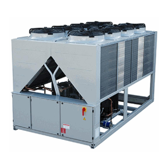
Air cooled scroll chiller
EWAQ~E- / EWAQ~F-
SS (Standard Efficiency - Standard Noise)
SL (Standard Efficiency - Low Noise)
SR (Standard Efficiency - Extra Low Noise)
XS (High Efficiency - Standard Noise)
XL (High Efficiency - Low Noise)
XR (High Efficiency - Extra Low Noise)
Cooling capacity from 171 to 675 kW
Refrigerant: R410A
English language: Original Instructions
D-EIMAC00801-17EN-AR - 1/44
Advertisement
Table of Contents

Subscribe to Our Youtube Channel
Related Manuals for Daikin EWAQ-E Series


Summary of Contents for Daikin EWAQ-E Series
- Page 1 Installation, Operation and Maintenance Manual D–EIMAC00801-17EN-AR Air cooled scroll chiller EWAQ~E- / EWAQ~F- SS (Standard Efficiency - Standard Noise) SL (Standard Efficiency - Low Noise) SR (Standard Efficiency - Extra Low Noise) XS (High Efficiency - Standard Noise) XL (High Efficiency - Low Noise) XR (High Efficiency - Extra Low Noise) Cooling capacity from 171 to 675 kW Refrigerant: R410A...
- Page 2 A – Typical refrigerant circuit – The number of compressors and water inlet and outlet are indicative. Please refer to the machine dimensional diagrams for exact water connections. D-EIMAC00801-17EN-AR - 2/44...
- Page 3 B – Typical refrigerant circuit with heat recovery – The number of compressors and water inlet and outlet are indicative. Please refer to the machine dimensional diagrams for exact water connections. D-EIMAC00801-17EN-AR - 3/44...
- Page 4 ENGLISH Compressor Discharge shut off valve ¼ SAE Flare Valve Condenser coil and Axial ventilator Service port Liquid line isolating valve Dehydration filter Liquid and humidity indicator Solenoid valve Electronic expansion valve Evaporator Suction shut off valve Low-pressure safety valve High-pressure safety valve Heat recovery (optional) Heat recovery solenoid valve...
-
Page 5: Operation
ENGLISH - ORIGINAL INSTRUCTIONS This manual is an important supporting document for qualified personnel but it is not intended to replace such personnel. Thank you for purchasing this chiller CONSIDERED ESSENTIAL DOCUMENTS OF THIS MANUAL READ THIS MANUAL CAREFULLY BEFORE In case of any discrepancy between this manual and the equipment’s documents please refer to on board documents. - Page 6 Label Identification 1 – Non flammable gas symbol 5 – Cable tightening warning 2 – Gas type 6 – Hazardous Voltage warning 3 – Unit nameplate data 7 – Electrical hazard symbol 4 – Manufacturer’s logo 8 – Lifting instructions Figure 2 - Operating limits Note The above graphic represents a guidelines about the operating limits of the range.
-
Page 7: Moving And Lifting
Installation Avoid installing the chiller in areas that could be dangerous during maintenance operations, such as Safety platforms without parapets or railings or areas not The unit must be firmly secured to the soil. complying with the clearance requirements around the It is essential to observe the following instructions: chiller. - Page 8 Figure 3 - Lifting the unit 4 fans version 5 fans version D-EIMAC00801-17EN-AR - 8/44...
- Page 9 6 fans version 6 fans version D-EIMAC00801-17EN-AR - 9/44...
-
Page 10: Minimum Space Requirements
10-12 fans version (The drawing shows only the 8 fans version. For the 10-12 fans version the lifting mode is the same) For installation on the ground, a strong concrete base, at least The water in the system must be particularly clean and all 250 mm thickness and wider than the unit must be provided. -
Page 11: Sound Protection
NOTE: Daikin cannot be considered responsible in case of lateral distance is lower than recommended, unless the malfunctions generated by hot air recirculation or insufficient... - Page 12 Fig. 4A Fig. 4B Fig. 4C Fig. 4D Fig. 4E Fig. 4F Fig. 4G Fig. 4H Figure 5 – Multiple Chiller Installation D-EIMAC00801-17EN-AR - 12/44...
- Page 13 7. A filter or device that can remove particles from the 9. The heat recovery device must be emptied of water fluid. The use of a filter extends the life of the during the winter season, unless an ethylene glycol evaporator and pump and helps to keep the water mixture in appropriate percentage is added to the system in a better condition.
-
Page 14: Water Treatment
Figure 5 - Water piping connection for evaporator Pressure Gauge Isolation Valve Flexible connector Pump Flow switch Filter Temperature probe Figure 6 - Water piping connection for heat recovery exchangers Pressure Gauge Isolation Valve Flexible connector Pump Temperature probe Filter reducing water flow. -
Page 15: Operator's Responsibilities
Before servicing the unit in any way, open the general Evaporator and recovery exchangers disconnecting switch on the unit’s main power supply. When the unit is off but the disconnecting switch is in the anti-freeze protection closed position, unused circuits are live, as well. All evaporators are supplied with a thermostatically controlled Never open the terminal board box of the compressors before having opened the unit’s general disconnecting switch. -
Page 16: Routine Maintenance
No safety device, either mechanical, electrical or pipes, etc..) with negative effect on performances and electronic must be disabled or overridden. functionality. The water used for filling the water circuit must be clean There are two different levels of maintenance, which can be and suitably treated. -
Page 17: Condenser Coil Maintenance And Cleaning Recommendations
Table 3 –Routine Maintenance Plan for Critical Application and/or Highly Aggressive Environment Weekly Monthly Yearly/Seas List of Activities (Note 8) (Note 1) Onal (Note 2) General: Reading of operating data (Note 3) Visual inspection of unit for any damage and/or loosening Verification of thermal insulation integrity Clean Paint where necessary... - Page 18 Important information regarding the refrigerant used This product contains fluorinated greenhouse gases. Do not vent gases into the atmosphere. Refrigerant type: R410A GWP(1) value: 2087,5 (1)GWP = Global Warming Potential The refrigerant quantity necessary for standard operation is indicated on the unit name plate. Real refrigerant quantity charged in the unit is listed on a silver sticker inside the electrical panel.
- Page 19 Factory and Field charged units instructions (Important information regarding the refrigerant used) The refrigerant system will be charged with fluorinated greenhouse gases. Do not vent gases into the atmosphere. 1 Fill in with indelible ink the refrigerant charge label supplied with the product as following instructions: the refrigerant charge for each circuit (1;...
- Page 20 Disposal The unit is made of metal, plastic and electronic parts. All these parts must be disposed of in accordance with the local regulations in terms of disposal. Lead batteries must be collected and sent to specific refuse collection centres. Oil must be collected and sent to specific refuse collection centres.
- Page 21 DECLARATION of CONFORMITY DAIKIN APPLIED EUROPE S.p.A Via Piani di Santa Maria, 72 - 00072 Ariccia (Roma) Italia → EWAQ080 EWAQ800 Declares that the Assemblies: (for manufacturing number and manufacturing year refer to unit nameplate) are conformal to the following Directives:...
- Page 22 The present publication is drawn up by of information only and does not constitute an offer binding upon Daikin Applied Europe S.p.A.. Daikin Applied Europe S.p.A. has compiled the content of this publication to the best of its knowledge. No express or implied warranty is given for the completeness, accuracy, reliability or fitness for particular purpose of its content, and the products and services presented therein.
- Page 23 دليل التركيب والتشغيل والصيانة D–EIMAC00801-17EN-AR مبرد حلزوني يبرد بالهواء EWAQ~E- / EWAQ~F- )الضوضاء القياسية (الكفاءة القياسية )الضوضاء المنخفضة (الكفاءة القياسية )الضوضاء المنخفضة ج د ًا (الكفاءة القياسية )قياسية الضوضاء ال (الكفاءة العالية )الضوضاء المنخفضة (الكفاءة العالية )الضوضاء المنخفضة ج د ًا (الكفاءة...
- Page 24 .الضواغط ومدخل ومخارج الماء إرشادي. ي ُرجى الرجوع إلى مخططات أبعاد الجهاز للحصول على التوصيالت الدقيقة للماء عدد – دائرة غاز التبريد النموذجية – أ أ D-EIMAC00801-17EN-AR - 24/44...
- Page 25 .د الجهاز للحصول على التوصيالت الدقيقة للماء ي ُرجى الرجوع إلى مخططات أبعا .عدد الضواغط ومدخل ومخارج الماء إرشادي – دائرة سائل التبريد النموذجية المزودة بوحدة استعادة الحرارة – ب ب D-EIMAC00801-17EN-AR - 25/44...
- Page 26 العربية الضاغط صمام إغالق التفريغ ¼ صمام إشعال ملف المكثف وجهاز تهوية محوري منفذ الخدمة صمام عزل خط السائل مرشح التجفيف مؤشر السائل والرطوبة صمام الملف اللولبي صمام التوسيع اإللكتروني المبخر صمام إغالق االمتصاص صمام أمان الضغط المنخفض صمام أمان الضغط العالي )استعادة...
- Page 27 اإلرشادات األصلية اإلنجليزية .ي ُ عد هذا الدليل وثيقة دعم مهمة للموظفين المؤهلين وليس المقصود منه أن يحل محل هؤالء الموظفين رد شكر ً ا لك على شرائك هذا المب في حالة وجود أي تعارض بين هذا الدليل ووثائق األجهزة، ي ُ رجى الرجوع إلى الوثائق .الداعمة.
- Page 28 تعريف الملصق تحذير ربط الكابل – رمز غاز غير قابل لالشتعال – تحذير جهد خطير – الغاز نوع – رمز خطر كهربائي – بيانات لوحة تسمية الوحدة – شعار الشركة المص ن ّ عة إرشادات الرفع – – حدود التشغيل الشكل...
- Page 29 التركيب تجنب تركيب المبرد في مناطق قد تكون خطيرة أثناء عمليات الصيانة، مثل األمان المنصات التي ال تحتوي على حواجز أو األسوار أو المناطق التي ال تتوافق مع .متطلبات الخلوص حول المبرد .يجب تثبيت الوحدة جي د ًا باألرض الضوضاء :ومن...
- Page 30 رفع الوحدة الشكل مراوح إصدار مراوح إصدار D-EIMAC00801-17EN-AR - 30/44...
- Page 31 مراوح إصدار مراوح إصدار D-EIMAC00801-17EN-AR - 31/44...
- Page 32 مروحة إصدار )مروحة، يكون وضع الرفع هو نفسه مراوح فقط. بالنسبة إلصدار (يعرض الرسم إصدار مم على األقل لتركيب الوحدة على األرض، يجب توفر قاعدة خرسانية قوية ب س ُ مك ى لمتطلبات المساحة الحد األدن وأوسع من الوحدة. يجب أن تكون هذه القاعدة قادرة على تحمل وزن الوحدة. يجب يجب...
- Page 33 .)(خزان توسيع وما إلى ذلك مسؤولة في حالة األعطال التي تنشأ نتيجة إعادة مالحظة: ال يمكن اعتبار شركة Daikin مؤشرات لدرجة حرارة المياه والضغط لمساعدة المشغل أثناء ن أو عدم كفاية تدفق الهواء نتيجة للتركيب غير السليم إذا ما تم تجاهل...
- Page 34 الشكل الشكل الشكل الشكل تركيب مبرد متعدد الشكل D-EIMAC00801-17EN-AR - 34/44...
- Page 35 مرشح أو جهاز يمكنه إزالة الشوائب من السائل. يزيد استخدام ة التدفئة من المياه أثناء فصل الشتاء ما يجب تفريغ جهاز استعاد مرشح من عمر المبخر والمضخة، كما يساعد في الحفاظ على لم تتم إضافة خليط من اإليثلين جليكول بنسبة مئوية مناسبة في كيب...
- Page 36 توصيل مواسير المياه لمبادالت استعادة التدفئة الشكل صمام عزل مقياس الضغط المضخة موصل مرن مرشح مجس درجة الحرارة تدفق المياه. لذا، تقلل معالجة المياه بطريقة صحيحة من خطر التآكل والتعرية والتقشر معالجة المياه .وما إلى ذلك. يجب استخدام معالجة المياه األنسب محل ي ً ا وف ق ً ا لخصائص النظام والمياه ال...
- Page 37 ويجب أن يحتفظ المشغل بسجل لبيانات التشغيل لكل وحدة مثبتة. ويجب أي ض ً ا االحتفاظ حماية المبخر ومبادالت االستعادة من التجمد .بسجل آخر لجميع أنشطة الصيانة والخدمة المتوقعة وإذا الحظ المشغل حاالت تشغيل غير طبيعية أو غير معتادة، ف ي ُ نصح بطلب االستشارة يتم...
- Page 38 برنامج الصيانة الدورية الجدول سنو ي ً ا/موسم ي ً ا شهر ي ً ا أسبوع ي ً ا قائمة األنشطة (مالحظة (مالحظة :عام الحظة قراءة بيانات التشغيل (م الفحص البصري للوحدة بح ث ً ا عن أي ضرر و/أو جزء مفكوك التحقق...
- Page 39 خطة الصيانة الدورية للتطبيقات المهمة و/أو البيئة شديدة الخطورة – الجدول سنو ي ً ا/موسم ي ً ا شهر ي ً ا أسبوع ي ً ا (مالحظة (مالحظة (مالحظة قائمة األنشطة :عام قراءة بيانات التشغيل (مالحظة الفحص البصري للوحدة بح ث ً ا عن أي ضرر و/أو جزء مفكوك التحقق...
- Page 40 معلومات مهمة تتعلق بغاز التبريد المستخدم .يحتوي هذا المنتج على غازات دفيئة مشبعة بالفلور. ال تطلق الغازات في الجو :نوع غاز التبريد R410A 2187.5 قيمة GWP(1) إمكانات االحترار العالمي .تتم اإلشارة إلى كمية غاز التبريد الالزمة للتشغيل القياسي على اللوحة االسمية للوحدة .تمت...
- Page 41 إرشادات المصنع ووحدات الحقل المشحونة )(معلومات مهمة تتعلق بغاز التبريد المستخدم .حن نظام غاز التبريد بغازات الدفيئة المشبعة بالفلور سيتم ش .ال تطلق الغازات في الجو :امأل ملصق شحن الغاز بالحبر الذي ال يمحى والمزود مع المنتج باإلرشادات التالية 2 ؛ 1 ؛...
- Page 42 التخلص من المنتج تم تصميم الوحدة من المعدن والبالستيك وقطع الغيار اإللكترونية. لذا، يجب التخلص من جميع هذه األجزاء وف ق ً ا للوائح المحلية المتعل .ات قة بالتخلص من المنتج .ويجب جمع بطاريات الرصاص وإرسالها إلى مراكز محددة لجمع النفايات .كما...
- Page 43 إعالن التوافق DAIKIN APPLIED EUROPE S.p.A Via Piani di Santa Maria, 72 - 00072 Ariccia (Roma) Italia EWAQ080 EWAQ800 → يعلن أن المجموعات لمعرفة رقم التصنيع وسنة التصنيع، راجع لوحة تسمية الوحدة متوافقة مع التوجيهات التالية بشأن التقريب بين قوانين الدول...
- Page 44 محتوى هذا المنشور على حد ما وصلت . جمعت تم إعداد المنشور الحالي لإلعالم فقط وال يشكل إلزا م ً ا على Daikin Applied Europe S.p.A Daikin Applied Europe S.p.A ة بهذه الوثيقة. تخضع المواصفات للتغيير عرفة. ليس هناك ضمانة باكتمال هذا المحتوى أو دقته أو موثوقيته أو مناسبته لغرض ما، ويسري ذلك أي ض ً ا على المنتجات والخدمات المقدم...
Need help?
Do you have a question about the EWAQ-E Series and is the answer not in the manual?
Questions and answers