Table of Contents
Advertisement
Quick Links
Advertisement
Table of Contents

Related Manuals for Devolo Magic2 LAN DINrail


Summary of Contents for Devolo Magic2 LAN DINrail
- Page 1 Manual devolo M agic 2 LAN DINrail...
- Page 2 Magic 2 LAN DINrail...
- Page 3 The reproduction and distribution of the documentation and software supplied with this product and the use of its contents is subject to written authorization from devolo. We reserve the right to make any alterations that arise as the result of technical de- velopment.
-
Page 4: Table Of Contents
Removing the devolo Magic adapter from a network ....... . . - Page 5 Warranty conditions ..............38 devolo Magic 2 LAN DINrail...
-
Page 6: Preface
Description of the icons devolo Magic! This section contains a brief description of the In no time at all, devolo Magic transforms your icons used in this manual and/or on the rating pla- house into a multimedia home that is ready for the te, the device connector, as well as the icons used future today. -
Page 7: Intended Use
The products are intended electronic equipment in the EU. for operation in the EU, Switzerland and Norway. * The only exceptions are devolo outdoor products, which are Additional information, backg- suited for the outdoor use thanks to their IP certification. -
Page 8: Ce Conformity
This product complies with the technical sion (e.g. Internet data). requirements of the directives 2014/35/ The devolo Magic 2 LAN DINrail is intended for in- EU, 2014/30/EU, 2011/65/EU und 2009/ stallation on the top-hat rail in the installation area 125/EC. -
Page 9: Introduction
9 Introduction 2 Introduction 2.1 devolo Magic Home is where devolo Magic is – in no time at all, devolo Magic transforms your house or flat into a multimedia home of the future with noticeably higher speed, more stability and greater range,... -
Page 10: Introduction To The Devolo Magic Adapter
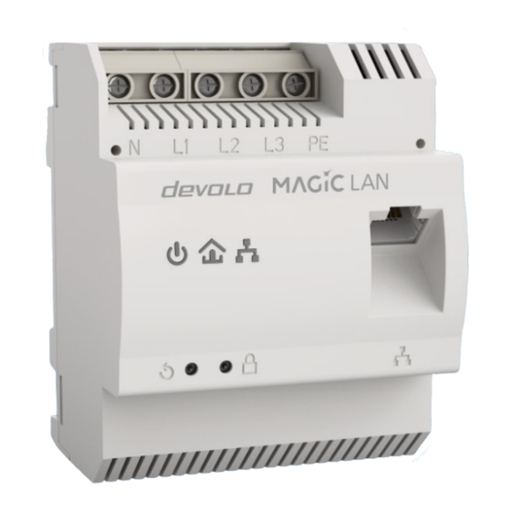
Energy-efficiency – the integrated PowerSave lings and walls. mode cuts energy consumption automatically To set up a devolo Magic network, you need at during low data traffic. least two devolo Magic devices. For technical reasons, devices from the devolo Magic series are not compatible with dLAN devices. - Page 11 11 Introduction Line connections Indicator lights Reset button PLC button Ethernet Fig.2 devolo Magic 2 LAN DINrail...
-
Page 12: The Devolo Magic Adapter Features
You can use the network connection (Fig. 2) on the The LED status display can be disabled. You can devolo Magic adapter to connect it to your inter- find more information about this in Chapter 5 net router using standard network cables. -
Page 13: Reading The Indicator Light
13 Introduction 2.3.3Reading the indicator light Power (Fig. 2) The integrated indicator lights (LED) show the sta- tus for the devolo Magic 2 LAN DINrail by illumina- ting and/or flashing: Power- Flashing Meaning LED status display haviour (web interface*) White... - Page 14 Red LED Flashes at in- Status 1: Cannot be disabled tervals of 0.5 The reset of the devolo Magic adapter was sec. (on/off) successful. The reset button has been pres- sed and held for 10 seconds. Status 2: The devolo Magic adapter (once again) has the factory default settings.
- Page 15 The other network nodes are in standby mode and cannot currently be accessed over the mains supply. The PLC LEDs of the other devolo Magic adapters flash white only for a short time. Status 2: The connection to the other network nodes has been interrupted.
- Page 16 White Lights up stea- The devolo Magic connection does not have Can be disabled any issues and the devolo Magic adapter is ready to operate. White Flashes at in- The devolo Magic adapter is in standby mo- Can be disabled tervals de.**...
- Page 17 As soon as the network device (e.g. computer) connected to the network interface is switched on again, your devolo Magic adapter can also be ac- cessed over the electrical wiring again. Check whether the adapter is connected to the mains supply correctly and whether the pairing operation has been carried out successfully.
-
Page 18: Plc Button
Expanding an existing devolo Magic network by adding another devolo Magic adapter found in Chapter 5 Configuration. In order to use a new devolo Magic 2 LAN DINrail 2.3.4PLC button in your devolo Magic network, first you have to connect it to your existing devolo Magic adapters devolo Magic adapters that are in factory default devices as a network. -
Page 19: Reset Button
(Fig. 2). Resetting a devolo Magic adapter or removing it from a devolo Magic network To remove a devolo Magic adapter from your devolo Magic network and successfully restore its entire configuration to the factory default settings, press and hold the reset button longer than 10 seconds. -
Page 20: Elektrical Installation
3.2 System requirements In this chapter we describe the electrical installati- Operating systems supported on of the devolo Magic 2 LAN DINrail on the top- devolo Cockpit: hat rail in the power distribution box. from Windows 7 (32-bit/64-bit), from Ubuntu 13.10 (32-bit/64-bit), 3.1 Package contents... -
Page 21: Important Safety Instructions
In the event of damage, contact customer ser- vice. This applies, for example, if devolo Magic 2 LAN DINrail... -
Page 22: Installation
Three-phase connection: Neutral conduc- 3.4 Installation tors and three external conductors are Install the devolo Magic 2 LAN DINrail properly connected to terminals N, L1, L2 and L3. on the top-hat rail. The device is supplied with power via ter- minals N and L1 (see Fig. - Page 23 Internet router). mise the data transmission, however, we re- commend a connection with all three-phases As soon as at least one other devolo Magic device and earth wire (PE). has been connected and plugged into the mains supply, a PLC network is set up. For information on how to proceed, refer to Chapter 4 Initial use.
-
Page 24: Initial Use
4.1.1 Changing the network password A network password can also be changed in the Before you can use the devolo Magic 2 LAN DINrail following ways: in your devolo Magic network, first you have to connect it to your existing devolo Magic adapters Using the web interface of the devolo Magic as a network. -
Page 25: Removing The Devolo Magic Adapter From A Network
Ubuntu 13.10 (32-bit/64-bit), from Mac (OS X 10.9) To remove a devolo Magic adapter from your net- You can find the product manual, software and work and successfully restore its entire configurati- additional information on devolo Cockpit onli- on to the factory default settings, press the reset ne at www.devolo.com/cockpit. -
Page 26: Configuration
5 Configuration You can find more information on devolo soft- ware in Chapter 4.2 Installation of devolo The devolo Magic 2 LAN DINrail has a built-in web software. interface that can be called up using a standard web browser. Here, you can read out device infor- 5.2 Menu description... - Page 27 Some fields include recommended settings. Once you make a change, two icons are shown on the corresponding menu page: Recommended settings can of course be replaced with customised information. Disk icon: Your settings are being saved. devolo Magic 2 LAN DINrail...
-
Page 28: Overview
Invalid entries 5.2.1 Overview In the Overview area, you will find information on Entry errors are either highlighted by a red border hardware and software for the devolo Magic ad- or error messages are shown. apter and network details. Buttons Click the Disk icon to save the settings for the respective web interface area. - Page 29 Magic adapters for your network along with displaying the following details: LAN – IPv4 Device ID: number of the respective devolo Magic DHCP: Display indicating whether DHCP is swit- adapter in the devolo Magic network ched on or switched off...
-
Page 30: Powerline
You can also assign your network a custom PLC password you pick yourself. Enter this password for In order to use a new devolo Magic 2 LAN DINrail each devolo Magic adapter in the Powerline in your devolo Magic network, first you have to password field and confirm your entry with OK. - Page 31 Unpairing – Resetting or removing an adapter to mitigate any potential negative effects. from a network To remove a devolo Magic adapter from your devolo Magic network, click Leave Powerline network. Wait until the PLC LED flashes white and then...
-
Page 32: Lan
You can access the web interface for the If you want automatic IP address assignment and devolo Magic 2 LAN DINrail using its current IP ad- there is already a DHCP server present on the net- dress. This may be an IPv4 and/or IPv6 address, work for giving out IP addresses (e.g. -
Page 33: System
Password. You can set a login password for accessing the web interface. By default, the built-in web interface of the devolo Magic 2 LAN DINrail is not protected by a password. We recommend assigning a password when installation devolo Magic 2 LAN DINrail is complete to protect it against tampering by third parties. - Page 34 Identify Device The devolo Magic adapter can be located using the Identify device function. Click Identify to make the white PLC LED for the corresponding adapter flash for 2 minutes to make it easier to identify by sight.
- Page 35 Wi-Fi is disabled. In this mode, the devolo Magic 2 LAN DINrail is not accessible over the Powerline network. As soon as the network device (e.g. computer) connected to...
- Page 36 Configuration 36 Manually initiate a firmware update Factory Settings In order to manually update the firmware, To remove a devolo Magic adapter from your visit the devolo website. devolo Magic network and successfully restore Download appropriate file its entire configuration to the factory default devolo Magic 2 LAN DINrail to your computer.
-
Page 37: Appendix
Contact your mu- nicipal government to find out the Temperature address and hours of the nearest collecti- (Storage/Operating -25°C to 70°C/ 0°C to 55°C on point. Dimensions (in mm) 90x73x66 (HxWxD) Ambient conditions 10-90% Humidity, non-condensing Certifications devolo Magic 2 LAN DINrail... -
Page 38: Warranty Conditions
Appendix 38 6.3 Warranty conditions If your devolo device is found to be defective du- ring initial installation or within the warranty peri- od, please contact the vendor who sold you the product. The vendor will take care of the repair or warranty claim for you. - Page 39 Disposal of old devices 37 Reboot 36 earth 22 Reset 12 Earth wire 12 Resetting a devolo Magic adapter 19 Expanding an existing devolo Magic network 18 External conductor 22 Safety instructions 21 Safety notes 8 Factory default settings 19 Single-phase connection 12...
Need help?
Do you have a question about the Magic2 LAN DINrail and is the answer not in the manual?
Questions and answers